 alnwlsn
Lucky for me, I have a design for a geiger counter which I made several years ago. It uses the classic and abundant Soviet SBM-20, which is a metal geiger tube running at 400V. It's a pretty standard design to what you'll find out there, but for the 400V power supply, the high voltage goes through a divider into an ADC pin, and it uses a PID loop in software to drive the main MOSFET via PWM. This works well enough to have a stable 400V with an Attiny84 running at 5V, and the PWM at about 4KHz. It's probably not even efficient, but geiger tubes need very little current, and it seems to work regardless. At one point, I made a PCB for it, which can drive a 7-segment display and handle a few button inputs, for a standalone counter, but for today, I only care about the power supply and detection circuitry, so I removed the speaker, and replaced the LED it makes blink with an optocoupler. This goes to an interrupt pin on a nearby Pi Pico W, which is where the counting actually takes place.
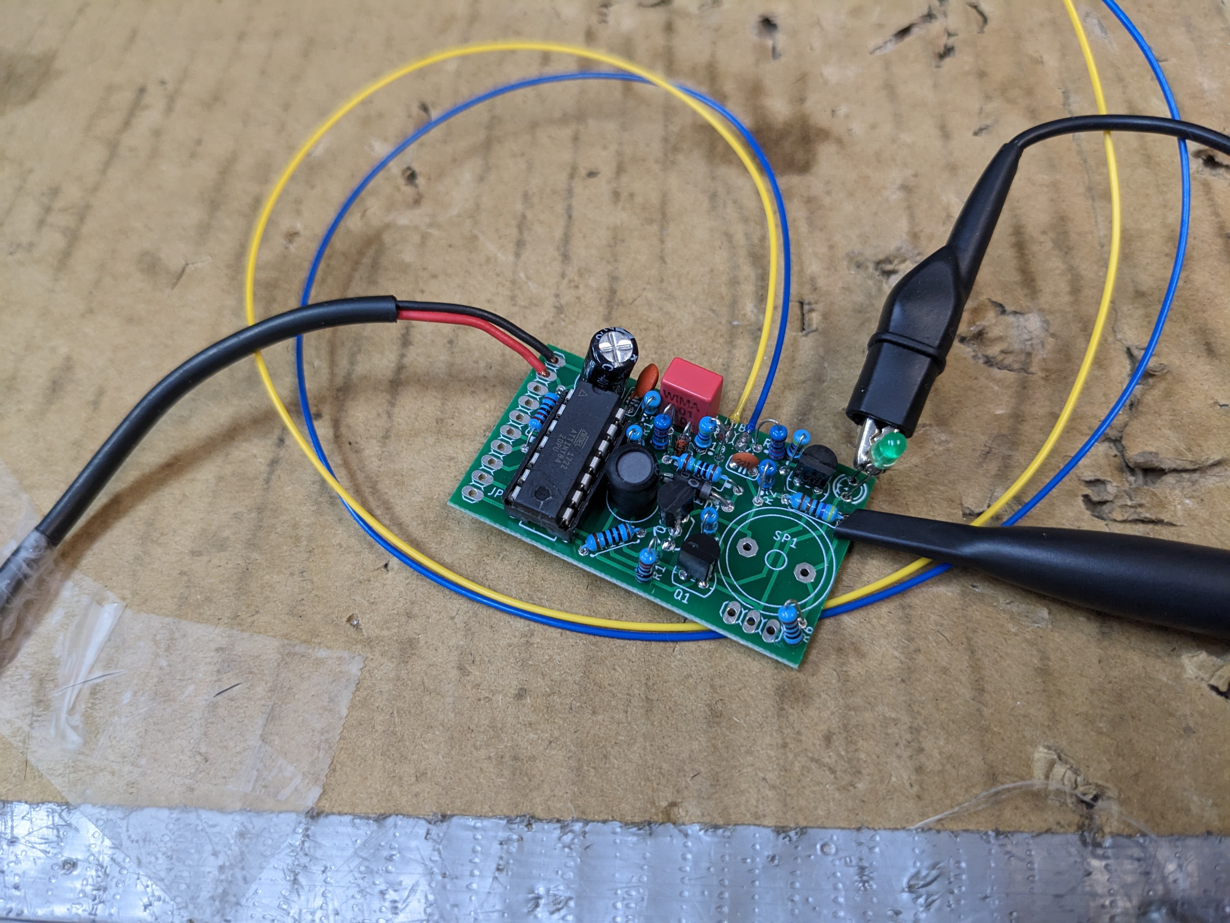
Testing the geiger counter PCB with an LED
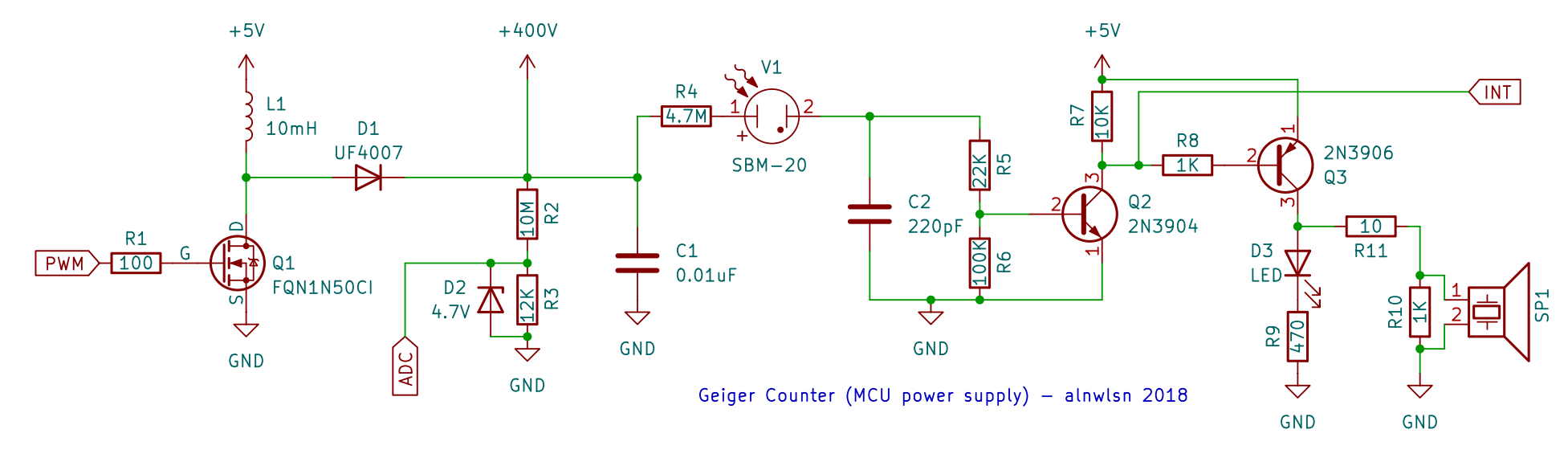
Schematic for my design (missing the MCU)
I have heard conflicting things about geiger tubes "wearing" or "breaking in"; for whatever difference it makes, I borrowed this tube from another counter which had been powered on for 1 year already, because I'm one of those people who has a bunch of sensors with ESP32s on them littered about the house.
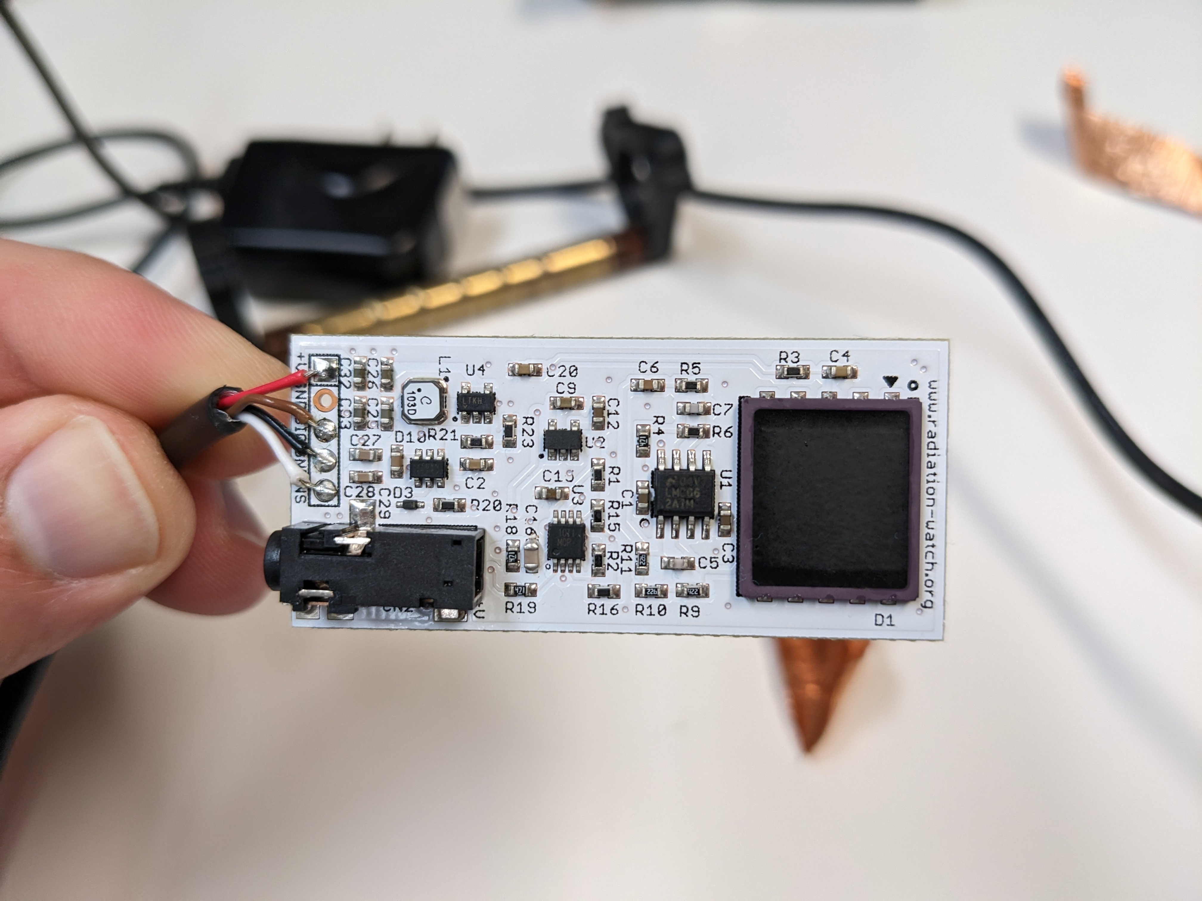
Since I expect this experiment to run for (potentially) years, I wanted to have a second type of radiation detector, just as a second data point. I wanted to do a PIN diode geiger counter, which instead of detecting a gas discharge inside a tube, it detects the tiny current generated when a radiation particle hits a silicon diode, somewhat like a solar panel. This signal is almost absurdly small, so much so that when you go to block the light from the diode package (the diodes only detect radiation in the dark), you have to be very careful not to get any paint across the diode leads, as this will be a low enough resistance to make the signal disappear. I tried building the well known Stuttgart Geigerle design. but I couldn't get it to work, so instead I bought a ready made unit: the Pocket Geiger Radiation Sensor - Type 5. This was a Japanese-built device made in response to Fukushima, designed to be attached to a cell phone headphone jack for on-the-go radiation monitoring (this was years before the Radiacode became everyone's favorite counter). It featured a 1 cm-square (large) X100-7 PIN diode which was pre-epoxied over to keep any light out. Unfortunately, since starting this project, that part was discontinued, followed by the removal of the Type 5 from stores not long afterwards.
The only problem with the Type 5 was that it was designed to alert you to slightly-higher-than-background levels, not scream-directly-in-your-ear levels, which is what we are effectively doing here. It uses a capacitor to stretch out those very short radiation pulses to something that a phone can pick up, but this leaves a recovery time of a few hundred ms, not the microseconds we're looking for. All I had to do here was swap out C16 for a much smaller capacitance. This did involve removing the copper foil tape shielding the sensitive portion of the board, but I replaced it with some fresh tape of my own.
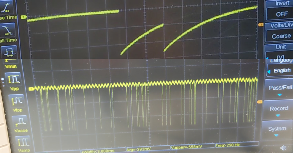
Here is the signal from the Type 5 before (top) and after (bottom) the fix. Note that the bottom is a more 'zoomed out' timescale, as more events now fit on the screen.
The Type 5 also includes a second output for 'noise'. I'm still not exactly sure what this is meant for, but I hooked it to another interrupt pin as well.
Radiation follows the inverse-square law, so for best results you want the source and detectors to be as close together as possible. I wanted something that would hold everything together securely, and be reasonably sealed so it would contain any specks of the source rock that flaked off, or radon gas produced within the decay chain. But, it should also be removable in case I wanted to change something in the future, so no sealing the whole thing in an epoxy cube here. Most importantly, it should be secure. The last thing I want is to measure this thing for half a year and bump it accidentally which moves the rock or one of the detectors, and I'd have to start all over.
I eventually came up with a series of TPU printed rubber inserts, which would press fit into the inside diameter of a short piece of PVC tube, and hold the rock, diode counter, and tube in position. I made some end caps for the tube out of TPU also, with some holes for wires. Note that only the geiger tube was inside the PVC tube, I decided to have the rest of the circuitry outside to avoid needing to open it again.
Finally, I attached a sticker to the outside. Probably the only time I'm going to use the radiation symbol legitimately.

For what it's worth, I have one of those digital radon meters in the same room (which also contains most of the small amount of other radioactive items I have), and it measures in at 0.64 pC/L, well below the action level for radon of any country.
Discussions
Become a Hackaday.io Member
Create an account to leave a comment. Already have an account? Log In.