 Bunn Wu
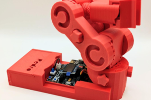
Robot-Wall is an exciting open-source robotics project designed to guide enthusiasts and developers in building a feature-rich and charming smart robot from the ground up. This project not only provides detailed hardware assembly instructions but also includes complete firmware source code, step-by-step programming guides, and promising future feature expansions. It serves as the perfect platform for you to enter the world of robotics and learn about embedded development and artificial intelligence applications.
Key highlights of the project include:
- Comprehensive Open-Source Resources: The project makes all necessary resources available on GitHub, including but not limited to hardware interface definitions, firmware source code, and detailed documentation, offering full support for your building process.
- Clear Development Roadmap: The project documentation presents a clear roadmap, with plans to incorporate more exciting features in the future, such as:
- 3D-printed and purchased parts lists
- Firmware flashing and calibration testing
- SD card support for storing more data and resources.
- I2C screen driver to add a visual interaction interface for the robot.
- Network configuration via a web page or Bluetooth for easy Wi-Fi setup.
- Voice wake-up and recognition to enable interaction with the robot through voice commands.
- Servo and motor control to achieve posture control and mobility.
Whether you are a student eager to learn embedded systems development, a maker passionate about DIY projects, or an engineer looking for an engaging hands-on project, Robot-Wall is an opportunity you won't want to miss. Join us now and start your journey of creating a smart robot
 Doan Hong Trung
 Vishwajeet Narwal
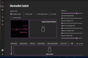
 Verdure Hiro 绿荫阿广