Close
0%
0%

Logic Lock

Unlock a secret box with Relay Logic against Raspberry Pi Pico W countdown timer.

Similar projects worth following
171 views
0 followers
In this project I use Relay Logic to provide a combination lock to a secret box. The operator is tasked with using their knowledge of Binary Numbers and Relay Logic to decode the combination lock. But there's a catch! Once the operator removes the cover to the locking system a timer is activated. If the lock is not decoded before the timer reaches zero the lock is permanently latched closed, cannot be opened and an alarm is activated. If the box is successfully opened the operator is faced with their next challenge...

I had three aims when coming up with this project:

Firstly to develop a fun and engaging way to teach aspiring electrical / electronics engineers to learn Relay Logic and Binary Numbers.

Secondly to finally use a Raspberry Pi Pico. I tend to use one of three flavours of Microcontroller in my projects, ESP32, Pic or ATmega. I've heard such great things about the Raspberry Pi Pico that I wanted a project to use it in so I could learn more about how to use it.

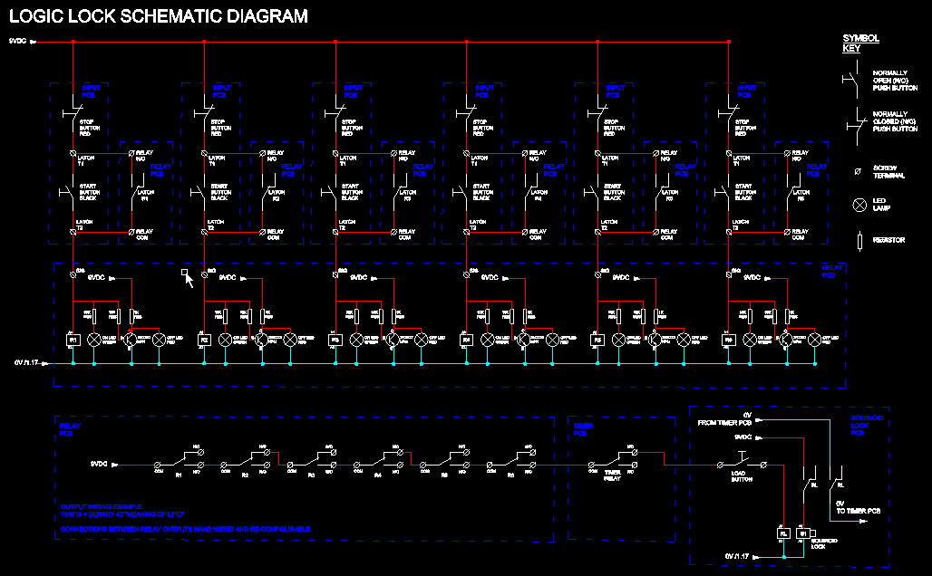
I teach how to build controls panels and PLC programming at my local community college. I start every new cohort with building a latching relay circuit, both physically and in PLC ladder Logic, as this is the building block of Industrial Controls Systems (ICS). 

This project is designed to give my students some fun and practical experience on working with latching relays.

The aim of this project is for the students to carry out all the wiring themselves, and in the process set-up their own unique combination for the Logic Lock.

To make it more interesting there is a timer in the circuit that prevents the lock from opening when it reaches zero. The timer activates as soon as the clear cover is removed and the microswitch activates. With the count drown dropping every second (at 1 Hz) it adds a bit more pressure to the code breaking challenge.

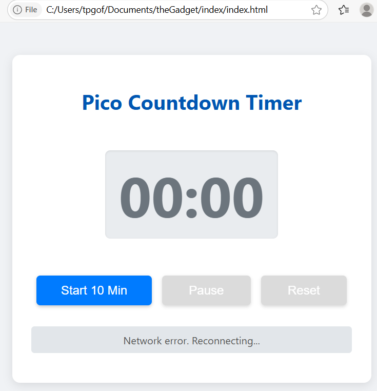
And in a sneaky twist I have made the Timer so you can control it with your phone. The Pico works as an access point and also hosts a website where the controller can manipulate the timer. This means even if some smart student works out how to bypass the micro switch the timer can still be activated remotely.

There's a full description of the build below but if you just want to see it in action take a look at this video.

PicoTimerCode.zip

The the files used for the PicoTimer - Main Python Code, TM1637 Python Code, Website HTML Code

x-zip-compressed - 8.49 kB - 08/14/2025 at 09:59

Download

ButtonBoard.zip

PCB Design Files for Button PCB

x-zip-compressed - 354.58 kB - 08/14/2025 at 09:41

Download

RelayBoard.zip

PCB Design Files for Relays PCB

x-zip-compressed - 1.03 MB - 08/14/2025 at 09:38

Download

LogicLockBoxPlans.dwg

Plans for laser cutting the box

DWG Drawing - 23.79 kB - 08/14/2025 at 09:35

Download

  • 1 × Input PLC Made by JLC PCB, files attached.
  • 1 × Relay PCB Made by JLC PCB, files attached.
  • 1 × Prototyping Board for Timer PCB
  • 1 × Prototyping Board for Solenoid Lock PCB
  • 6 × Push-to-break push buttons for Input PCB 5mm Pitch - Available from Digikey

View all 27 components

  • 1
    Relay Logic

    At the heart of this project is a series of six latching relays. The output of the latching relays are connected in series. The latching relays can either be latched "on", binary number 1, or latched "off" binary number 0. The contacts of all six relays is wired in series through a timer relay and a  "load" button. The relays can be wired in series through either the Normally Closed contact or the Normally Open Contact.

    When the relay is latch on a Green LED is illuminated and when the relay is latch off a Red LED is illuminated.

    The relay outputs are hand wired and you change the combination of the lock by either wiring them through the Normally Open or Normally Closed Contact. For example, if you wire the relays as follows: 

    Relay 1 = N/C  LED = Red

    Relay 2 = N/O LED = Green

    Relay 3 = N/C LED = Red

    Relay 4 = N/C LED = Red

    Relay 5 = N/O LED = Green

    Relay 6 = N/O LED = Green

    The above would be represented by the binary number string 010011 and therefore Denary number 19.

    Relay 6 is the Least Significant Bit, and the binary number string produced is Big-Endian.

    The timer relay is in the Normally Closed state, however if the timer reaches zero before the correct combination is chosen this relay Opens and the correct combination cannot be loaded to open the lock.

    When all the six relays are in the correct configuration then the loop is complete up to the load button. When the load button is pressed the lock will open.

    The schematic drawing is in the files, take a look if you want to understand this system in more detail.

  • 2
    Raspberry Pi Pico Countdown Timer

    Despite having being gifted several of these microcontrollers, before undertaking this project I had never used a Raspberry Pi Pico. I have been intrigued by the the Pico for a while as very few people seem to go back to other controllers after using them (for hobby projects anyway). 

    I found connecting up and writing code for the digital inputs and outputs to the Pico very straight forward, even with my limited Python coding experience. I also wanted to learn about the WiFi capability of the Raspberry Pi Pico so it is setup to be both an Access Point (AP) and web server. You can then use your phone to connect to the Pico and View, Start, Stop and Pause the timer.

    There's a total of three files that need to be uploaded to the Pico, these are:

    main.py  - The "master program" written in MicroPython that controls the Pico and accesses the index.html and tm1637.py files.

    index.html - Provides the code for the website interface.

    tm1637.py - is a MicroPython driver file that provides the necessary functions and classes to control and display numbers on a TM1637 4-digit 7-segment display module. I like having the tm1637 on the board as it gives a real "Hollywood" feel to the project, especially with the clocks second ticking down at a frequency of 1Hz.

    I have included all of the above files however here's an overview of how the code works

    1. Wi-Fi Setup

    The code begins by configuring the Raspberry Pi Pico W to act as a Wi-Fi Access Point (AP). This means it creates its own wireless network named "PicoTimer" with the password "micropython". When a phone or computer connects to this network and opens a browser, it can control the countdown timer through a web interface. This is handled by the setup_ap() function.

    2. Hardware Initialization

    Several GPIO pins are used to connect to physical hardware:

    • TM1637 4-digit display shows the countdown (connected to Vcc, Gnd, GPIO2 to DIO and GPIO3 to DIO).

    • Pullup Input on GPIO 12 starts the timer when connected to GND.

    • Pullup Input on GPIO 4 resets the timer to 00:00 when connected to GND.

    • Buzzer on GPIO 16 sounds when the timer finishes.

    • Output on GPIO 11 could be used to trigger an external device, like a misting system.

    Each of these pins is set up at the start of the script.

    3. Timer State Tracking

    A dictionary named timer_state stores everything needed for timing:

    • Whether the countdown is active.

    • How many seconds are left.

    • When the last second tick happened.

    • The total duration (default is 1 minute).

    This makes it easy to share and update timer information throughout the program.

    4. Web Server Functionality

    The Pico runs a small web server that listens for incoming HTTP requests on port 80. When someone connects (e.g. using a phone or laptop), the Pico:

    • Sends back the web page (index.html)

    • Responds to commands like /start_timer, /pause_timer, /reset_timer, and /get_status.

    The handle_request() function processes these commands. It can also send back JSON data, which the webpage can use to display timer updates in real time.

    HTML is sent in small chunks to avoid memory errors. This is helpful when sending large pages over a small microcontroller.

    5. Input Handling (Physical)

    When the physical input is activated, the timer starts and the display is updated. The reset input stops the timer, resets it to zero, and clears the display. Debouncing (a simple timing check) is used to prevent false triggers when the input is triggered.

    6. Timer Logic and Display

    The main loop continuously:

    1. Accepts and handles any new web requests.

    2. Checks if the timer is running.

    3. If a second has passed, it reduces the countdown by one.

    4. Updates the display with the new time.

    When the timer reaches zero:

    • The buzzer oscillates (buzzes) five times.

    • The output pin goes high to activate the external device.

    • The display is dimmed and reset to 00:00.

     7. Main Program Flow

    The main() function runs everything:

    • Sets up the Wi-Fi and web server.

    • Waits for web requests or button presses.

    • Manages the countdown and output hardware.

    • Uses short delays to avoid overloading the CPU.

  • 3
    The Web Interface

    All projects seem to need a web interface or App. For this project I decided to create a web interface so that I could control the timer from my phone.

    The index.html file contains the script for the webpage, here's an overview of the code in this file.

    This HTML page creates a user-friendly web interface for controlling the Raspberry Pi Pico W countdown timer. Users can start, pause, and reset the timer directly from their phone or computer after connecting to the Pico’s Wi-Fi.

    Layout and Styling

    The page usesCSS to create a clean design:

    • A large timer display (e.g. 00:00) shows the remaining time.

    • Three buttons let the user start a 10-minute countdown, pause it, or reset it.

    • A status message area shows feedback like "Countdown active" or "Network error".

    • The layout automatically adjusts for mobile screens.

     Button Actions

    Each button sends a command to the Pico:

    • Start sends /start_timer

    • Pause sends /pause_timer

    • Reset sends /reset_timer

    These commands are handled by the Pico's web server (in main.py).

    Live Countdown Display

    Every second, JavaScript on the page calls /get_status to:

    • Get the current time left (in seconds)

    • Show it in MM:SS format

    • Enable/disable the buttons based on the timer state

    This makes the web interface update in real time, just like the physical display on the Pico.

    Error Handling

    The JavaScript also:

    • Detects network errors and stops polling temporarily

    • Displays helpful messages when commands fail

    This keeps the page stable, even if the Wi-Fi signal is weak or if the Pico is rebooted.

View all 6 instructions

Enjoy this project?

Share

Discussions

Similar Projects

Does this project spark your interest?

Become a member to follow this project and never miss any updates