 Tim
TimNow that we have a source of stable oscillations—remind you, FROM FIRE—we need to convert them into an electrical signal.
For my original investigations, I used an I²C-based light sensor to sample the light signal. This provides very high SNR, but is comparatively complex.
Phototransistor
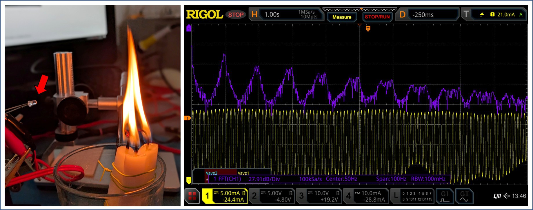
Looking for a simpler solution, I tried using a phototransistor. This worked quite nicely. Below you can see the setup with a phototransistor in a 3mm wired package (arrow). Since the phototransistor has internal gain, it provides a much higher current than a photodiode and can be easily picked up without additional amplification.
The phototransistor was connected via a sensing resistor to a constant voltage source, with the oscilloscope connected across the sensing resistor. The output signal was quite stable and showed a nice ~9.9 Hz oscillation.
In the next step, this could be connected to an ADC input of a microcontroller to process the signal further.
But who has a phototransistor in their parts bin anyway? There must be an even simpler solution.
No Parts (Capacitive Sensing)
Capacitive touch peripherals are part of many microcontrollers and can be easily implemented with an integrated ADC by measuring discharge rates versus an integrated pull-up resistor, or by a charge-sharing approach in a capacitive ADC.
While this is not the most obvious way of measuring changes in a flame, I expected to see some variations. The heated flame with all its combustion products contains ionized molecules to some degree and is likely to have different dielectric properties (permittivity) compared to the surrounding air. Measuring the capacitance between electrodes that are close to the flame or immersed in the flame should therefore allow to detect variations of the flame, which will be observed as either a change of capacitance or increased electrical loss.
A quick internet search also revealed publications on capacitance-based flame detectors.
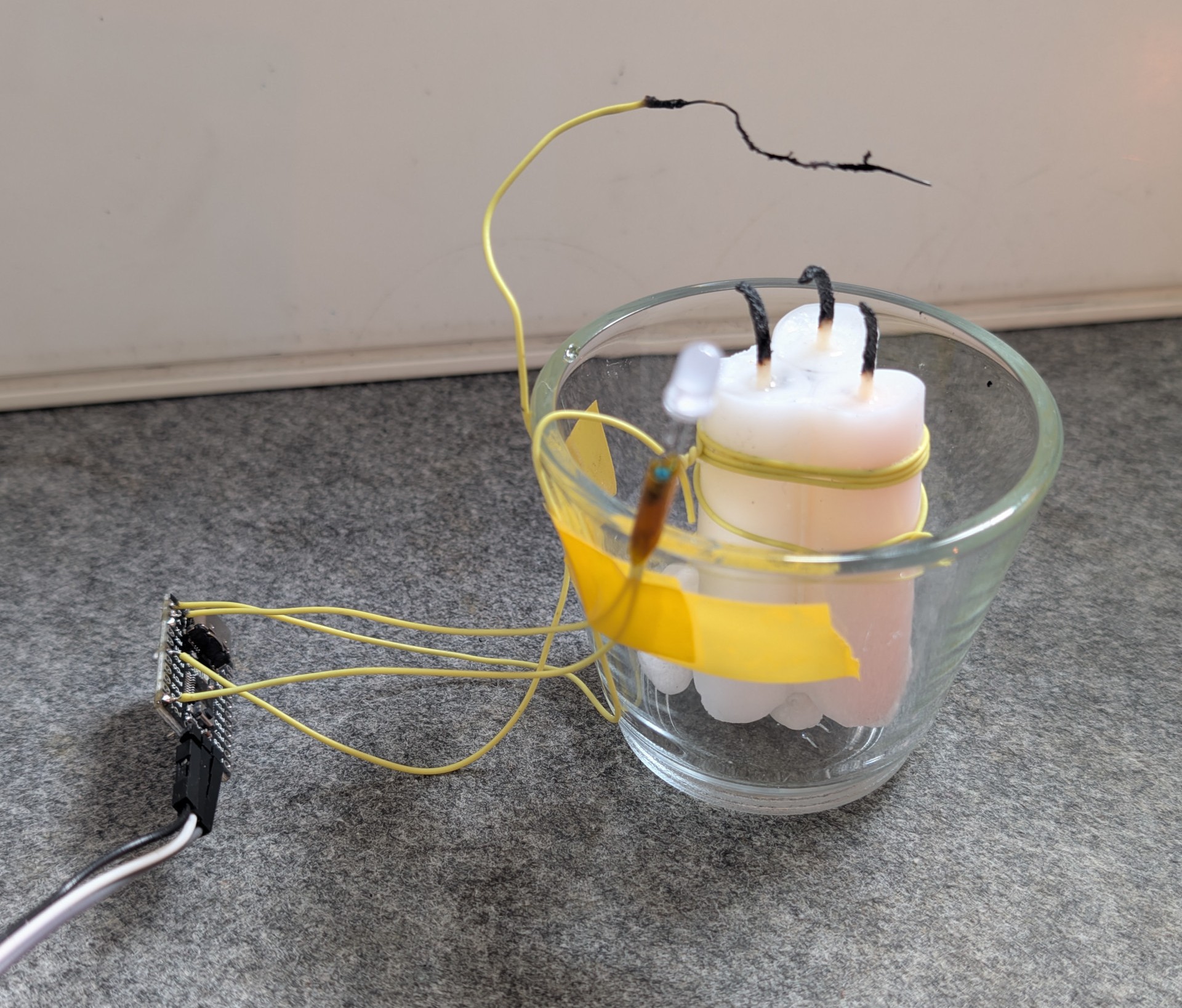
To implement the capacitive sensor, I opted to use a CH32V003 microcontroller with the CH32fun environment. You can see the full contraption below: the microcontroller is located on the small PCB to the left. The capacitance is sensed between a wire suspended in the flame (the scorched one) and a ground wire that is wound around the candle. The setup is completed with an LED as an output.
I also made some attempts with two wires in the flame, but did not necessarily get better results and the setup was mechanically much more unstable.
Reading out the sensor was quite straightforward using the TouchADC function that is part of CH32fun. This function measures the capacitance on an input pin by charging it to a voltage and measuring voltage decay while it is discharged via a pull-up/pull-down resistor. To reduce noise, it was necessary to average 32 measurements.
// Enable GPIOD, C and ADC
RCC->APB2PCENR |= RCC_APB2Periph_GPIOA | RCC_APB2Periph_GPIOD | RCC_APB2Periph_GPIOC | RCC_APB2Periph_ADC1;

InitTouchADC();
...

int iterations = 32;
sum = ReadTouchPin( GPIOA, 2, 0, iterations );
And indeed, it works! The sample trace below shows sequential measurements of a flickering candle until it was blown out at the end, as signified by the steep drop of the signal. The sampled data was transmitted as ASCII output via the console.
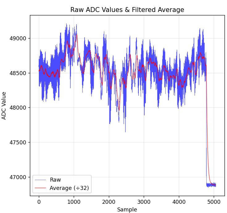
The signal has a lower amplitde than the optical signal and shows more baseline wander and amplitude drift—but we can work with that. Let's put it all together.
Discussions
Become a Hackaday.io Member
Create an account to leave a comment. Already have an account? Log In.