Lithium ION
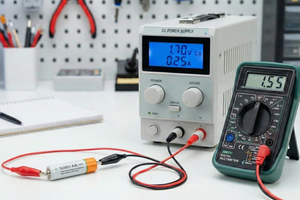
Today, we will learn how a battery charge cycle works. I have designed a lot of battery charging modules. Most of them are based on Li-ion batteries, so here in this tutorial, with the help of a lab bench power supply, I will demonstrate how a Li-ion can be directly charged without any external charging or protection circuit. If there is no circuit, then you should be there to monitor the charging. More than that, we will replicate the exact behaviour of a well-known battery charging IC, TP4056. Which is basically a 1A constant current/constant voltage battery charger IC. very popular due to its availability and low price. It can charge in constant current (CC) and constant voltage (CV) modes. We will see how these modes are decided. So let's begin with the IC specifications first.

This project is sponsored by PCBWAY, I have been using the PCB services for so long and I can trust PCBWAY's quality and services. They always deliver on time, and more importantly, I am amazed by the quality. Try PCBWAY using this link and get free coupons on your first sign-up.
Battery Charging Modes:

- Trickle Charge Mode (Conditioning): If battery voltage is <3V, a low current trickle charge is applied. In this case, only 1/10th of the constant current is applied to the battery for safety purposes. So that battery can be pulled back to the state of charge.
- Constant Current (CC) Mode: When battery voltage rises above 3V, the programmed charge current (set by RPROG) is applied. Constant current mode is nothing but just a current limiting phenomenon; we are basically limiting the maximum charging current to the IC. It will be discussed further in more detail.
- Constant Voltage (CV) Mode: As the battery approaches 4.2V, the charging current tapers off. This is basically filling the battery from 90% to 100%, this is important for good battery health but we can also plug out the battery after CC mode is done.
How the Charging IC works:
As per the battery voltage, the IC pulled in one of the above-given 3 modes. The current is controlled through an external programmable resistor, which just applies a restriction to the max current. IC’s like TP4056 limit the charge current based on die temperature during high power operation or high ambient temperature.

In case of lithium ions the charge voltage is fixed at 4.2V. Automatically terminates the charge cycle when the charge current drops to 1/10th of the programmed value after reaching the final float voltage. Other features of a battery PMIC include cell temperature monitor, under-voltage lockout, automatic recharge, and two LED status indication pins for charge termination and presence of an input voltage. The basic circuit is given above.
How Batteries Are Generally Charged:
BASIC METHOD: There will be two dominating modes: CC/CV. These two modes are common for LiPo and Li-Ion. CC is nothing but a constant current (limited current) mode, and similarly, CV is a limited voltage mode. Either we can control voltage or current at one time, but both can not be controlled at the same time unless limited by the power supply.
Say if a battery can charge at 10A, then as the voltage increases, it drops down to 9-8-7-6…to zero Ampere. This is an old method and is not used much, because it requires high currents which can not be handled with small-scale integrated circuits.
ADVANCE CHARGING: A discharged battery is charged in CC mode, it gets constant current, and the voltage starts increasing. As the voltage increases, the charging current decreases. But it does not show because the battery is demanding 10A, and we are only giving 1A. So it charges 10x slowly, and when the point reaches where battery voltage is sufficiently high, and it needs less than 1A to charge, then it shifts CC to CV mode.
One more thing to note, during CC mode, the power supply voltage can be shifted a little higher, say 4.2 to 6V, it will not damage the battery because the voltage is not constant, hence drops to the same potential...
Read more »
 Sagar 001
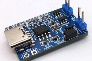
 Stefan Wagner