 Wouter Minjauw
A video of the pendulum in operation
To see the pendulum in operation, just have a look at the video.
The idea behind it
The idea behind this project was to create a solar powered pendulum in the simplest way possible, without any transistors. This is easier said than done, as most of us know how to design with transistors, but we have lost the knowledge to design something without them.
The problem that needs to be solved
The problem is that in order to make the pendulum oscillate, some sort of AC force must be applied to the pendulum, but a solar cell provides DC output. So the main problem boils down to can you generate an AC force on a mechanical system by using DC solar cells.
The answer is yes, but it requires some out of the box thinking, and some may consider the solution as 'cheating'. However, the goal was not to use transistors, so anything is allowed as long as no transistors are used.
Generating force
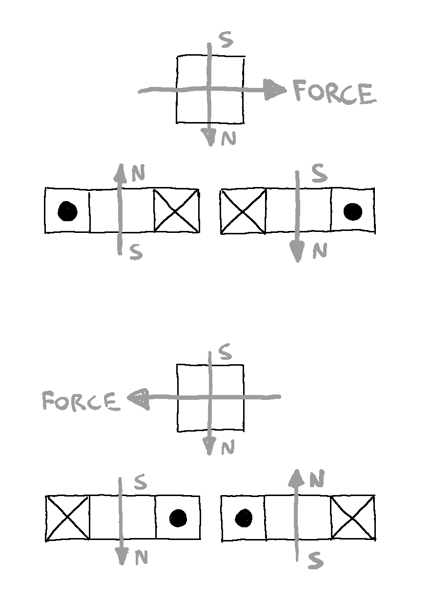
To generate force on the pendulum, a magnet is put on the pendulum, and coils are used below the magnet to push the magnet. The picture below shows a cross section of the two coils that are used in the device, and how current should be passed through them in order to generate a magnetic force to the right or to the left, depending on the direction of the current through the coils.
Creating an AC source with DC solar cells
If no transistors can be used to create an 'inverter' which turns DC into AC, a different solution is needed. A lot of experiments were performed with the pendulum partially shading it's own solar cell in order to get some AC voltage superimposed on the DC output of the solar cell, but the results were disappointing. Although you can get some AC voltage on top of the DC voltage, the power you can get out of it is very limited.
A much better solution turned out to be using two solar cells, and wiring them in anti-parallel, as can be seen in the following schematic of the device.
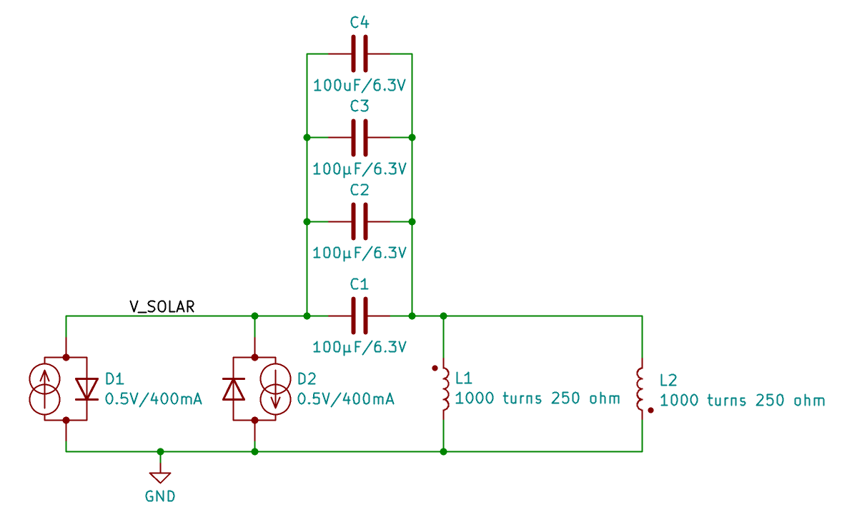
Each solar cell can be modeled as a light-dependent current source, with an intrinsic diode in parallel. If the pendulum is in the center, then both cells will be 50% shaded. The left solar cell pushes 200mA from GND to V_SOLAR, and the right solar cell pulls 200mA from V_SOLAR to GND. Both currents balance each other out, and no current flows through the intrinsic diodes of the cells, V_SOLAR is thereby 0V.
If the pendulum swings to the left, then the left solar cell will be (for instance) 75% shaded and the right solar cell 25% shaded. The left solar cell will now push 100mA from GND to V_SOLAR, the right solar cell will pull 300mA from V_SOLAR to GND. As Kirchoff's laws must be obeyed, 200mA will flow through the intrinsic diode of the right solar cell, resulting in V_SOLAR become a few hunderd millivolts negative. Similarly, if the pendulum swings to the right, V_SOLAR becomes a few hundred millivolts positive.
A sinusoidal movement of the pendulum results in a sinusoidal current of the solar cells, but due to the nonlinear I-V characteristic of the intrinsic diodes, the waveform of V_SOLAR starts to look more like a quare wave than a sine, which will turn out to be beneficial later on.
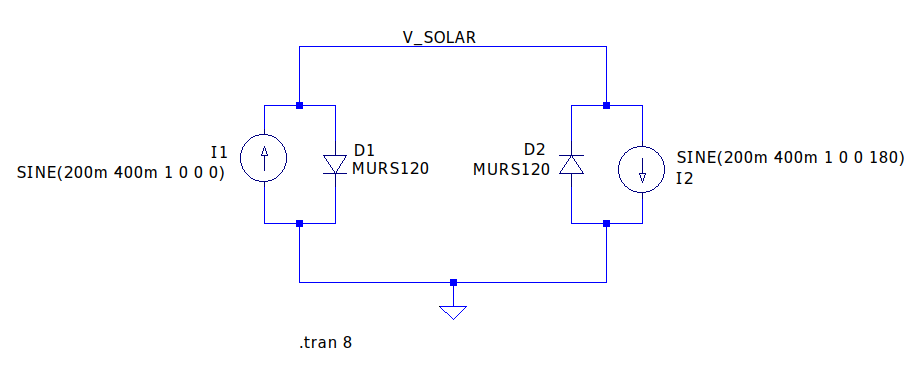
The pictures below show a simulation of the solar generator and the resulting V_SOLAR voltage. (The exact model of the diodes doesn't really matter, we just want to show the general behavior here.)
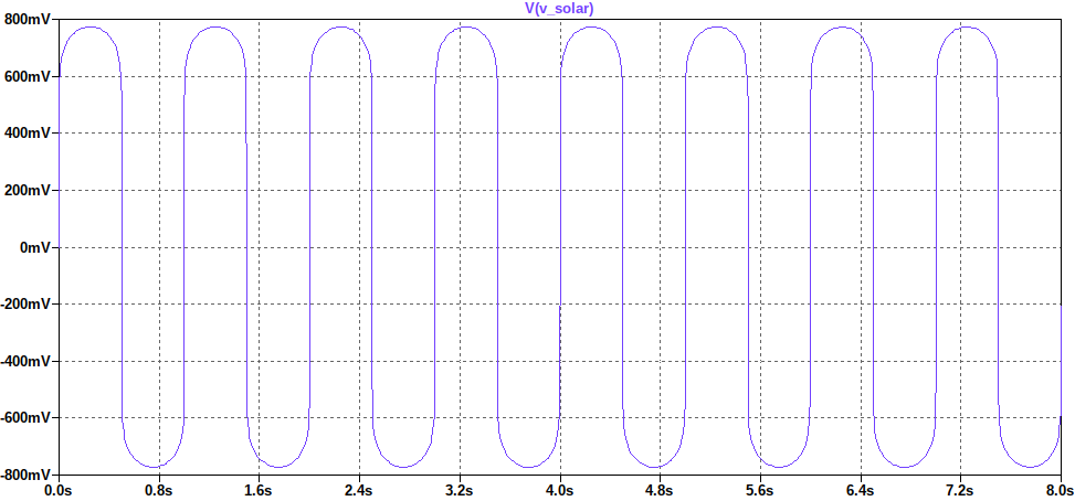
The dv/dt slope of the voltage is the highest at the zero crossings of the V_SOLAR, and this occurs when the pendulum passes through the mechanical center, shading both solar cells equally. Looking back at the magnetics picture earlier, this exactly when force should be generated on the magnet. In order to provide the right force at the right time, some capacitors in parallel are connected between V_SOLAR and the coils. Due to the I=C*dv/dt behavior of the capacitor, it will pass the most current through the coils at the zero crossings of the waveform, and that's exactly when we need it.


 ridoluc
 JP Gleyzes

 gfresources.video
Nice, when I was still a pupil I built something like this with a magnet as pendulum and a reed switch. I guess that's the standard way of doing it without transistors. Of course, the fancy way is to use the coil to sense the pendulum.