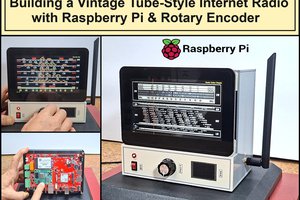
mircemk
Software-defined radio (SDR) is a radio communication system where components that have traditionally been implemented in analog hardware (such as mixers, filters, amplifiers, modulators, and demodulators) are instead implemented by means of software on a computer or embedded system. The biggest advantage of SDR is its flexibility. Because the functions are handled by software, you can change the radio's behavior by simply updating the software.
This time I will present you a wonderful example of how to make such a receiver using Raspberry Pi Pico.
Even this receiver works completely independently without the use of a PC and all functions are controlled directly on it and displayed on a small OLED display. The original project is presented on the 101 things website and the author is Jon Dawson, so all credits go to him. Also there are many more exelent Raspberry Pi Pico projects on this site and I hope to test and promote some of them in the near future.
This project is sponsored by PCBWay. . Visit the PCBWaywebsite and save big, with a time-limited promotion on purple solder mask. From September 1st to September 30th you can get 10 pcs of 2-layer 100x100mm PCBs in purple for only $5. PCBWay has all the services you need to create your project at the best price.

The receiver consists of a minimal number of components, but its huge number of functions and possibilities for various settings can rival even expensive commercial devices of this kind.

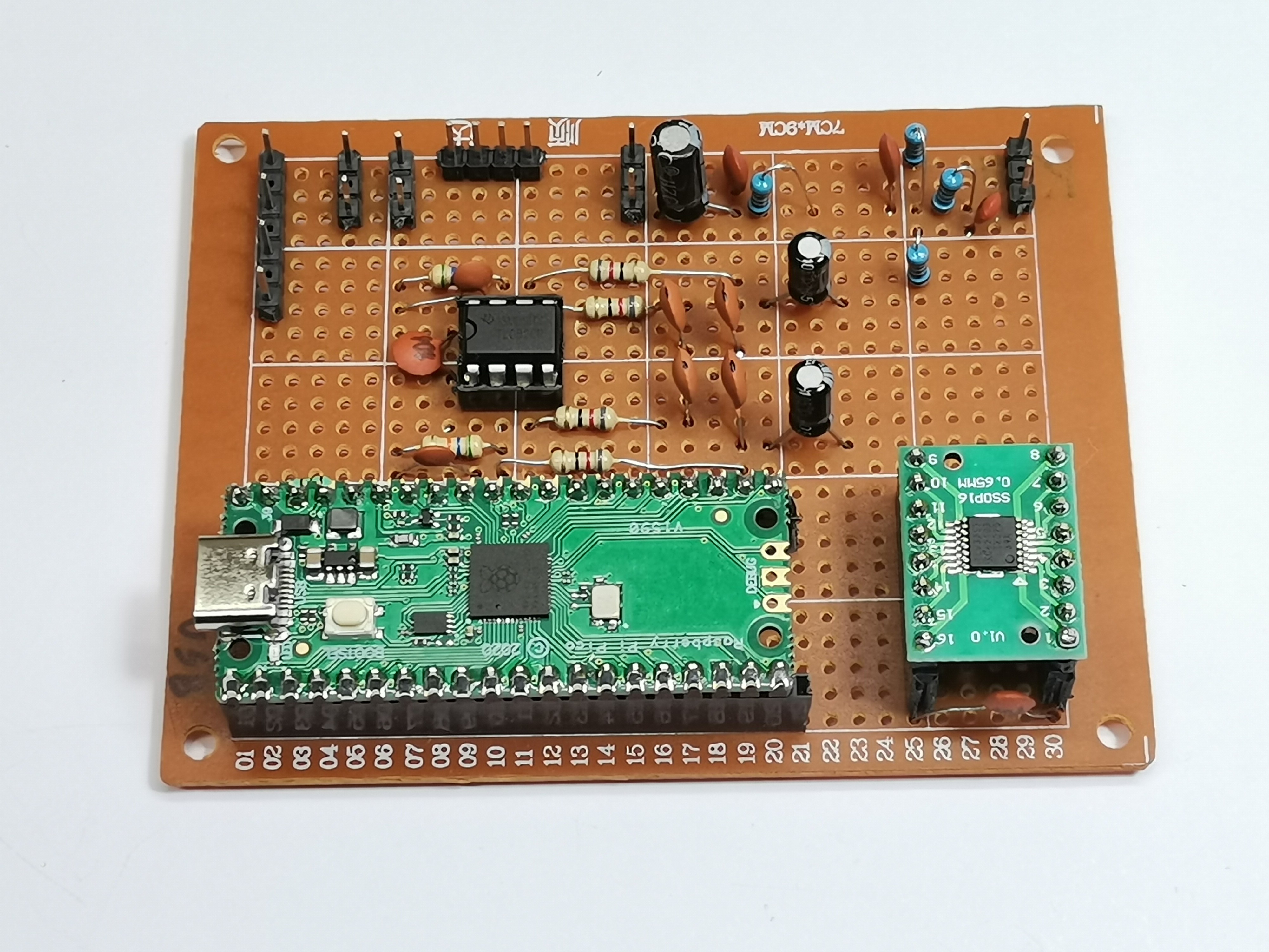
I made complete device on a universal PCB, and as you can see, the layout of the components is almost identical to the breadboard version of the schematic presented on the source page. I made the complete project on PCB in less than a day and was positively surprised by the fact that the device worked immediately upon first powering on.
The basic components are clearly visible and they are:
- Raspberry Pi Pico module
- CBTLV3253 Multiplexer IC
- TL082 Dual Operational Amplifier IC (I use it instead of MCP 6022, and NE5532 can also be used)
- SSD1306 OLED Display
- and rotary Encoder and two buttons
Now just a few words about installing the code. The GitHub page provides binaries for the Raspberry Pi Pico and the newer Raspberry Pi Pico2, in the form of a .uf2 file. This means that the installation is extremely simple. We need to hold down the button on the Pico and plug in the USB. Now the Pico is presented in "This PC" as a mass storage device and we need to simply copy the provided .uf2 file into it.

With this, the installation of the code is complete.
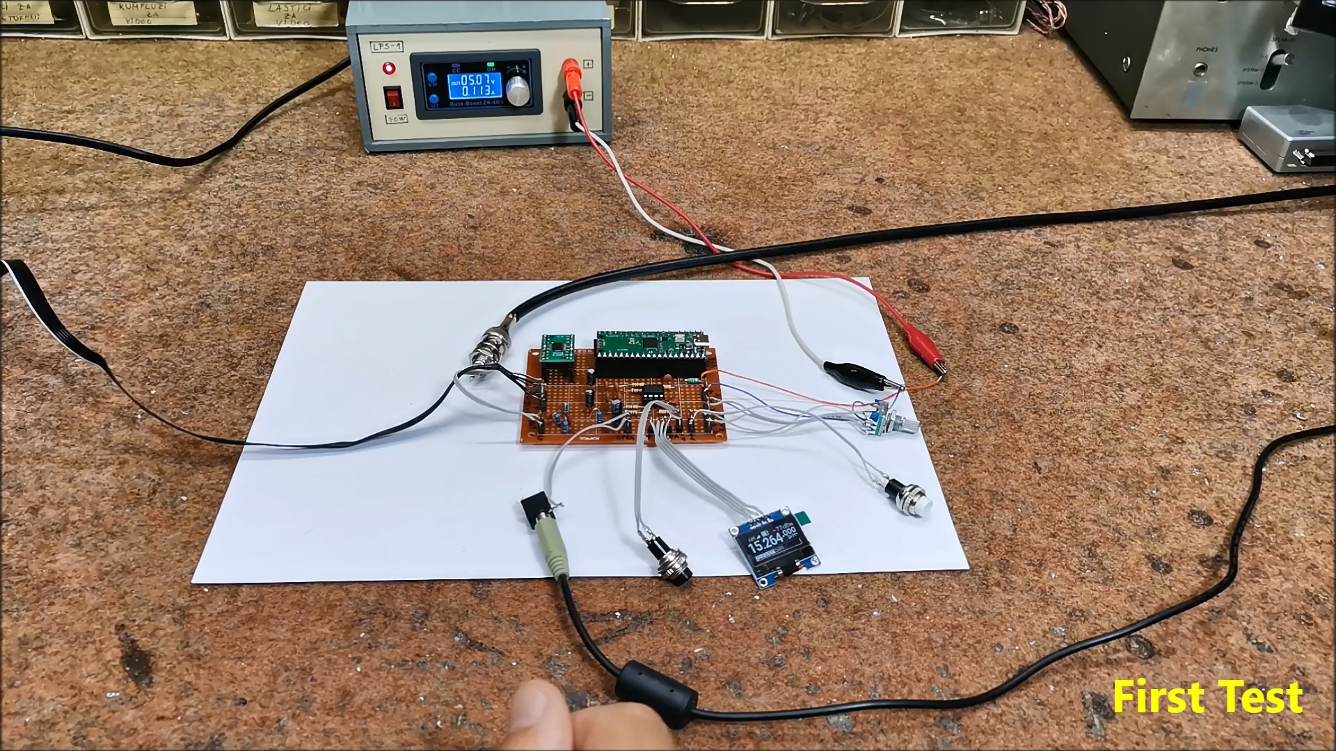
Now comes the first power-up of the device and a short test. I connected the audio output from the receiver to the "Line In" input of the PC sound card. For now, I connect a simple "long wire" antenna and try to receive a Broadcast station to confirm the functionality.
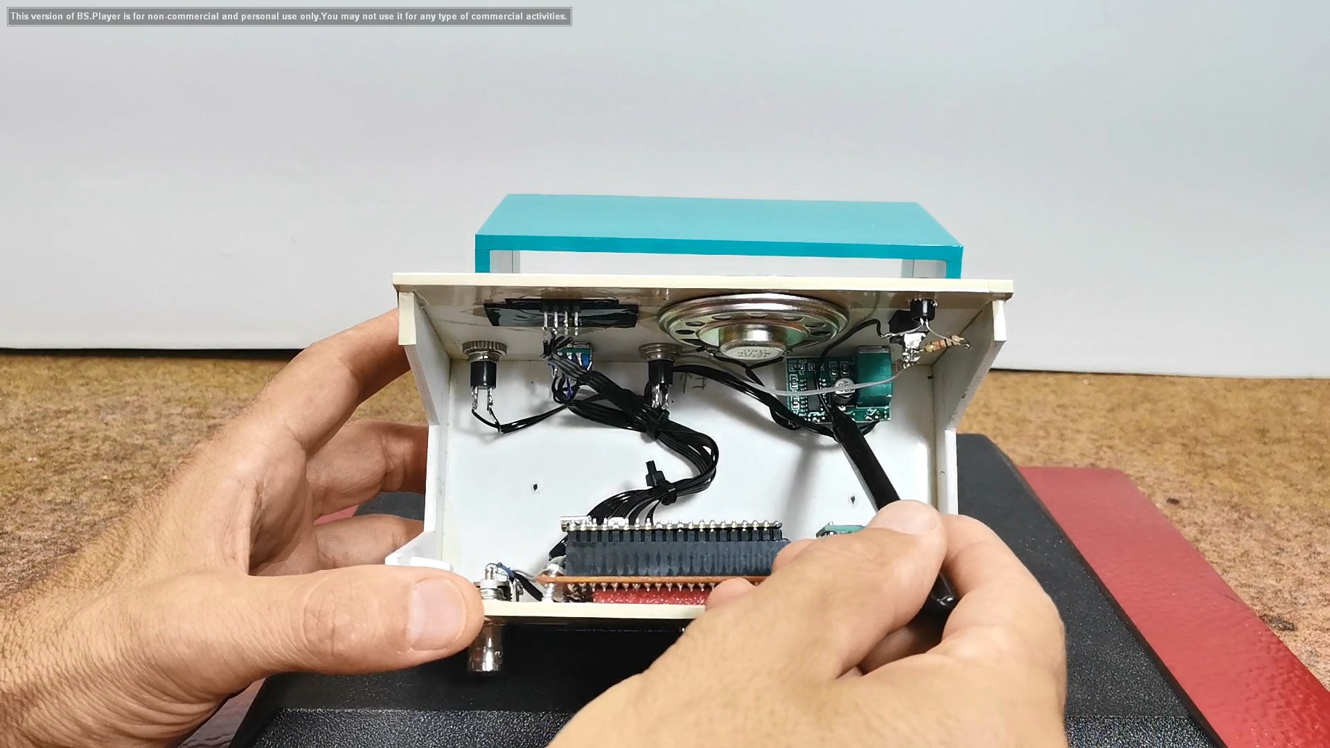
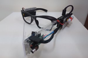
This is what the finished Pico SDR Receiver looks like placed in a suitable housing with the Display and control buttons on the front panel and the power and antenna connection on the back.
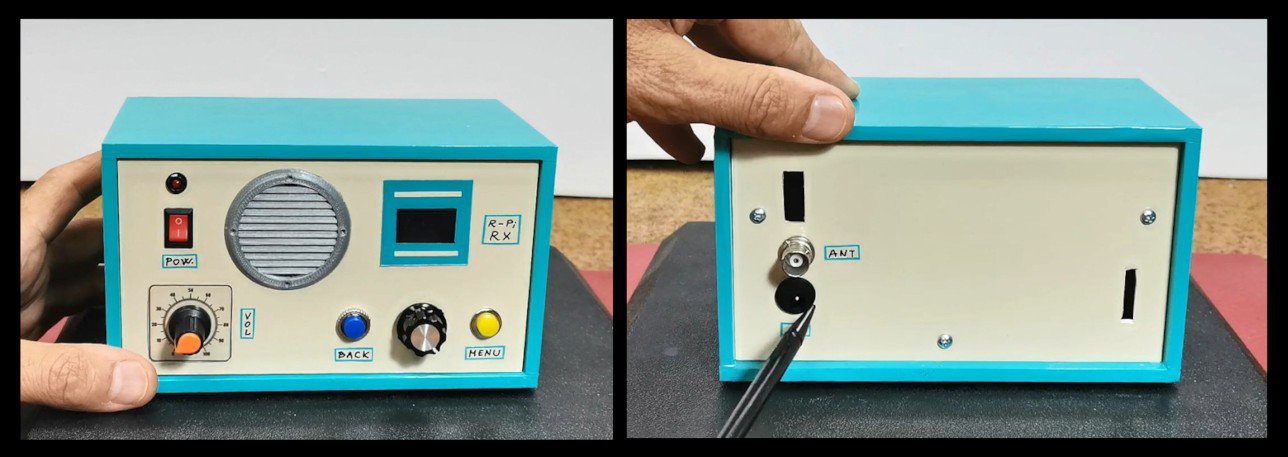
If we look inside the box we will see that in addition to the universal PCB it also have a D-class Audio Amplifier module along with a small speaker so the SDR receiver is completely independent keeping in mind that instead of an external power supply we can install Lithium batteries with charger circuit.
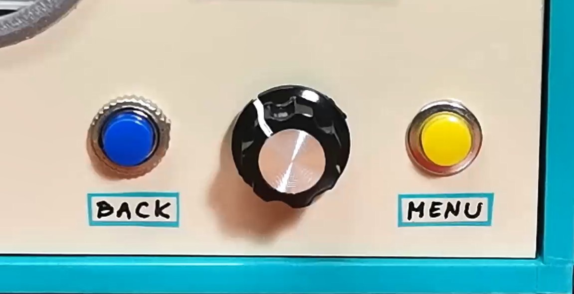
Now I will just briefly "walk" through the menu to look at all the functions and possibilities. To explain all these functions individually would take us a really long time. At the end of this text is the original manual according to which you can study all the functions in more detail. For setting the options we have two buttons MENU and BACK plus Rotary encoder with built-in button.
When turning on the receiver, the display shows the information that has been saved since the last operation.
Even at the start, on this small display it has many useful functions:
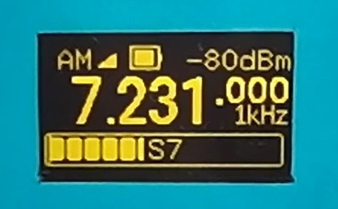
- In the...
Read more »
 Liam Z. Charles
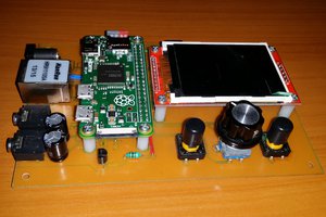
 Marek Więcek