Close
0%
0%

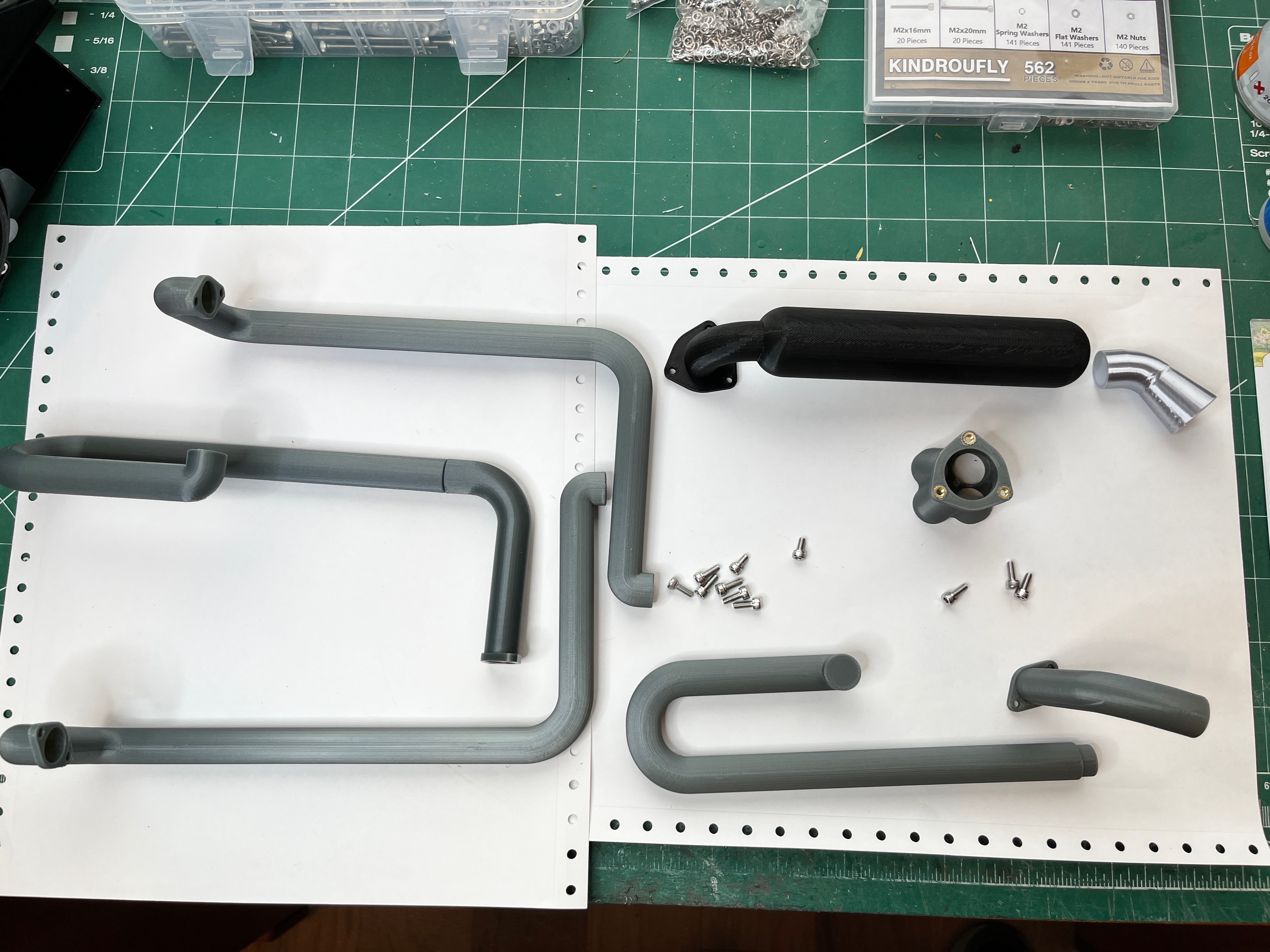
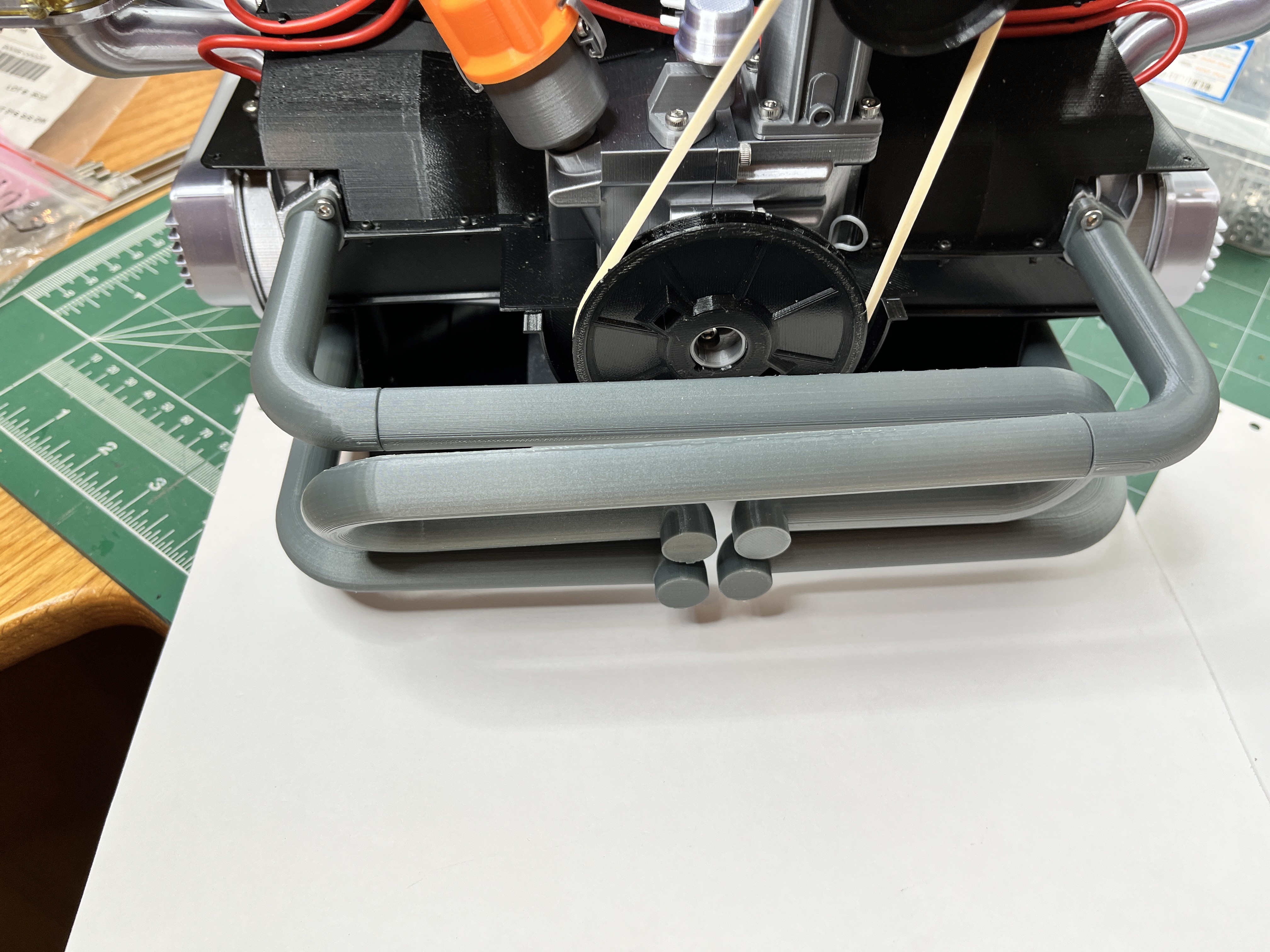
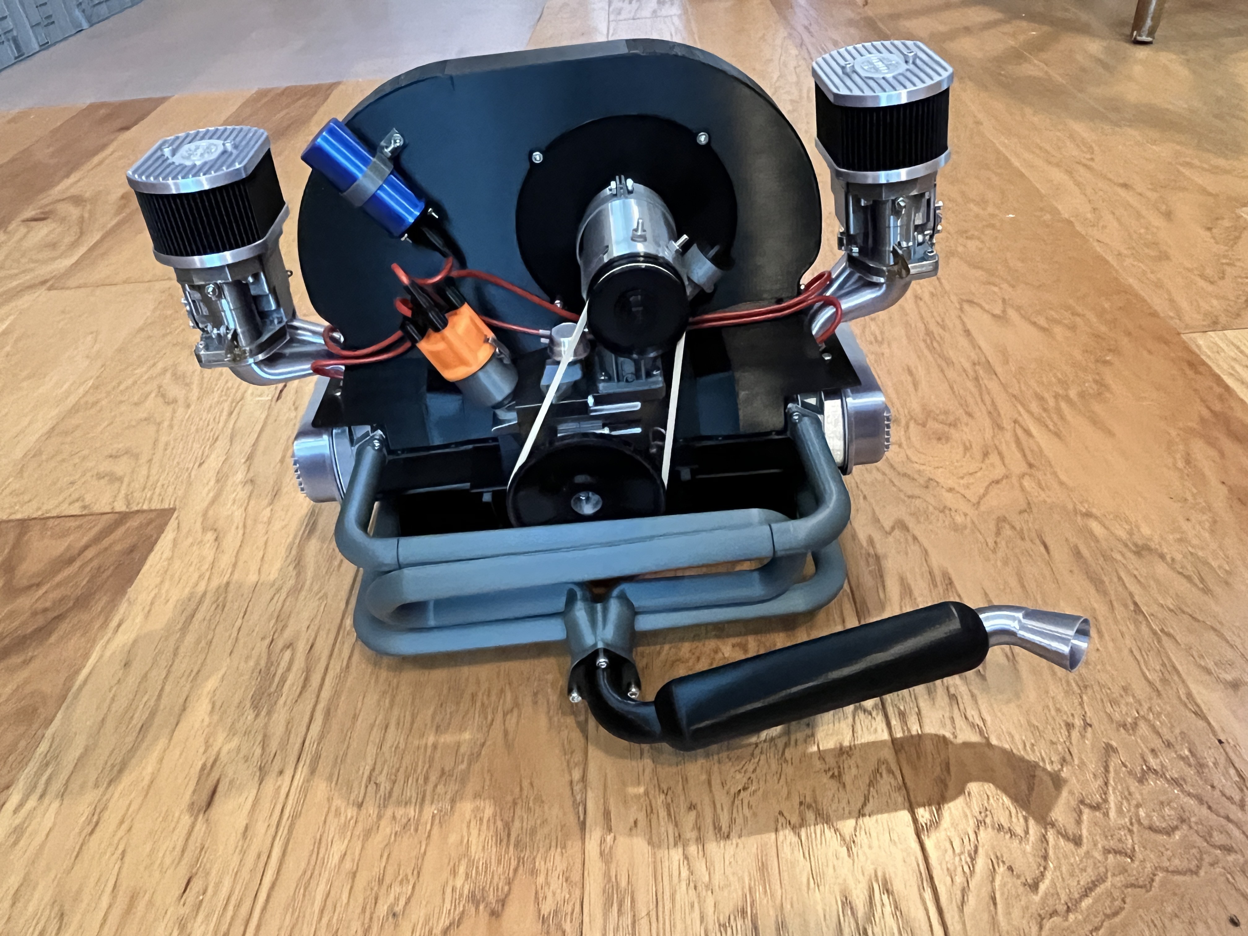
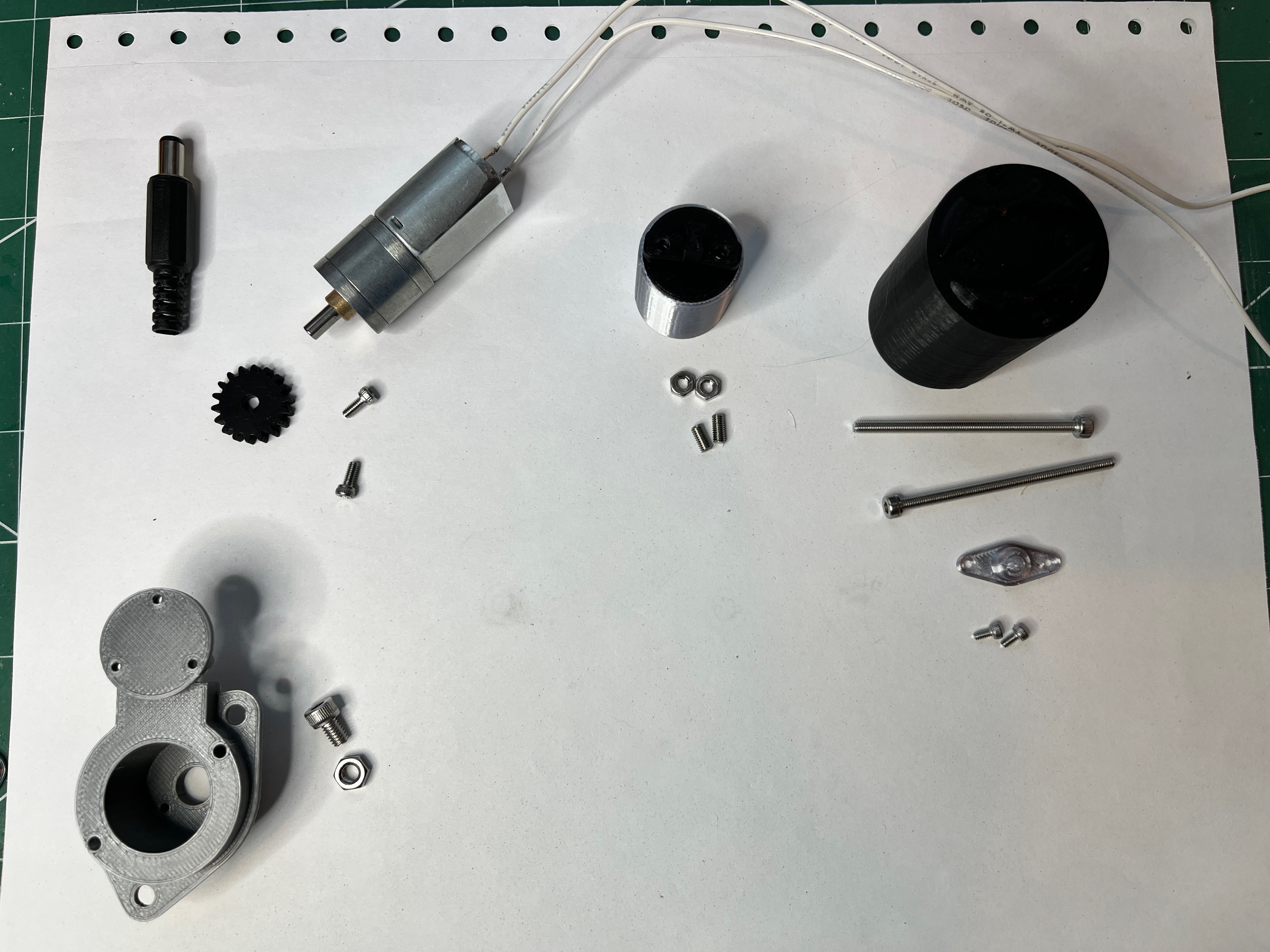
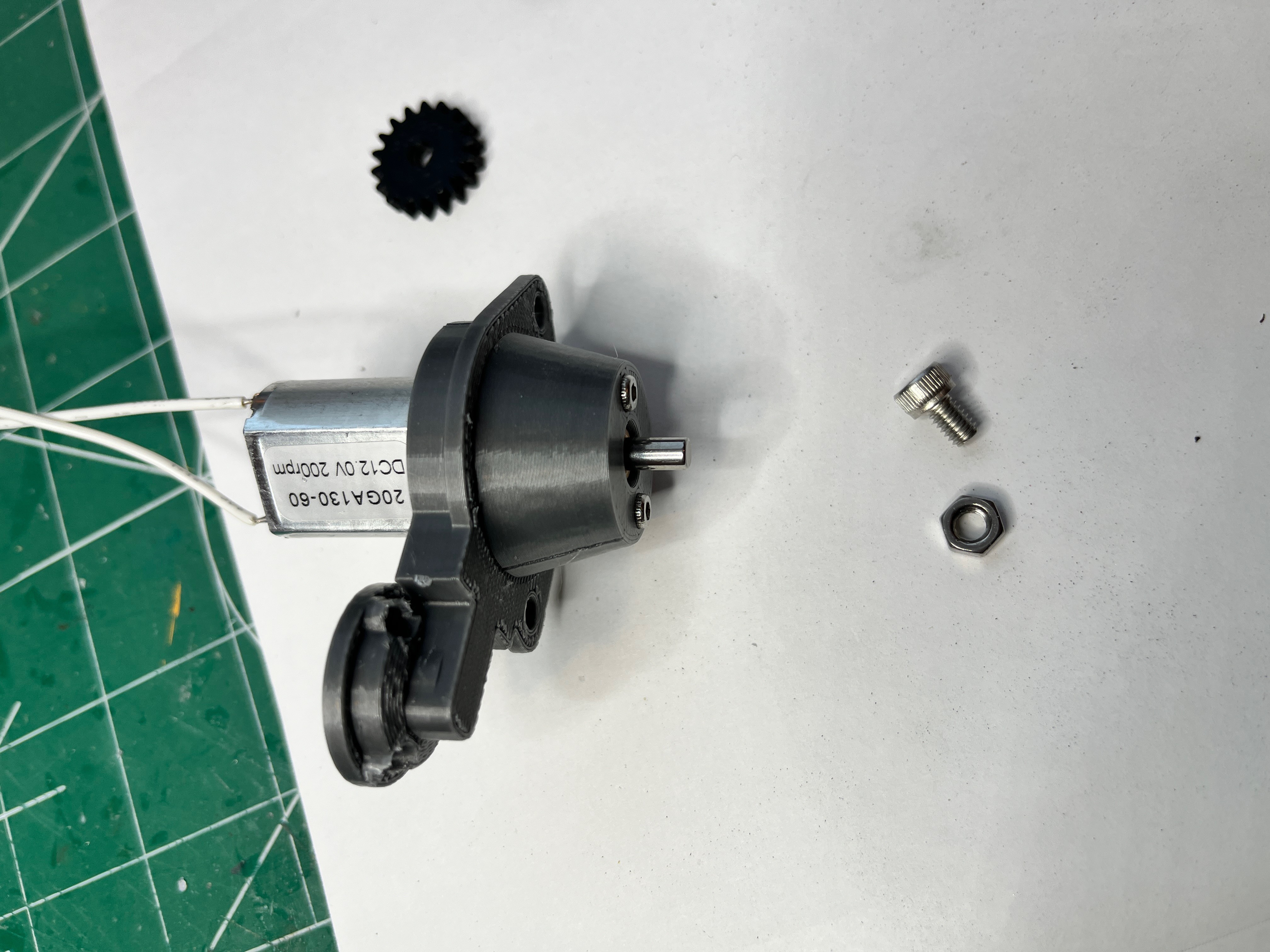
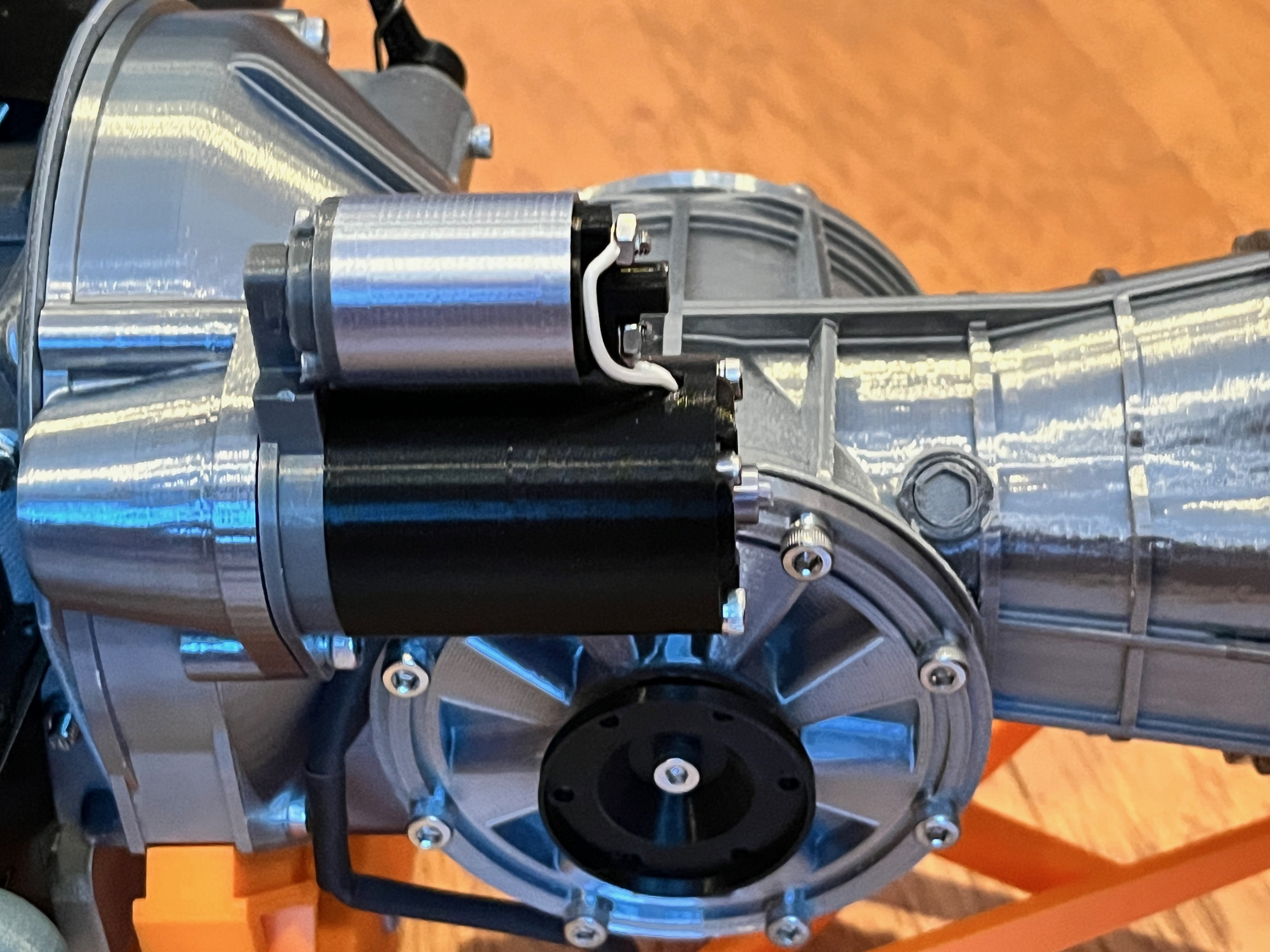
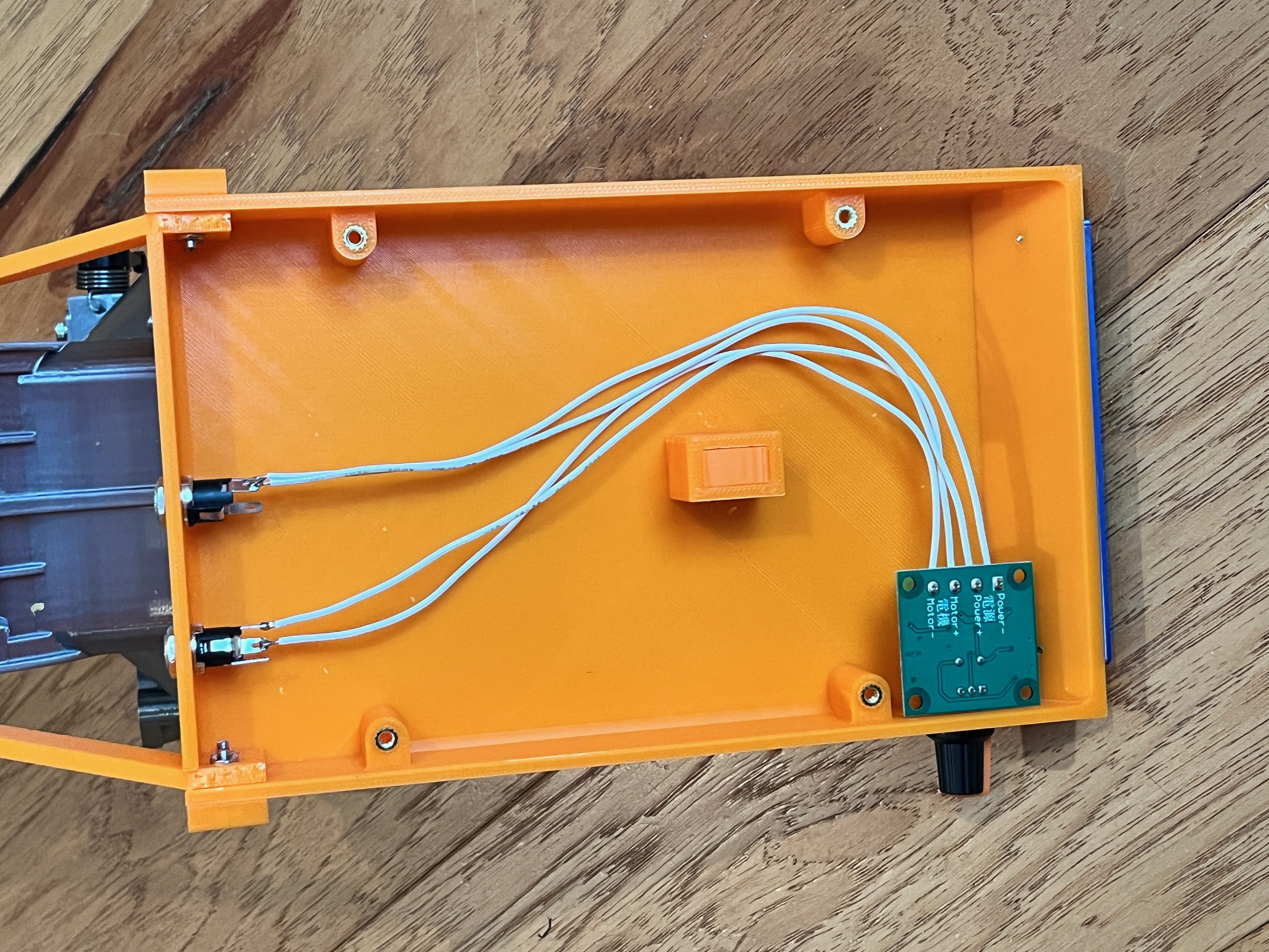
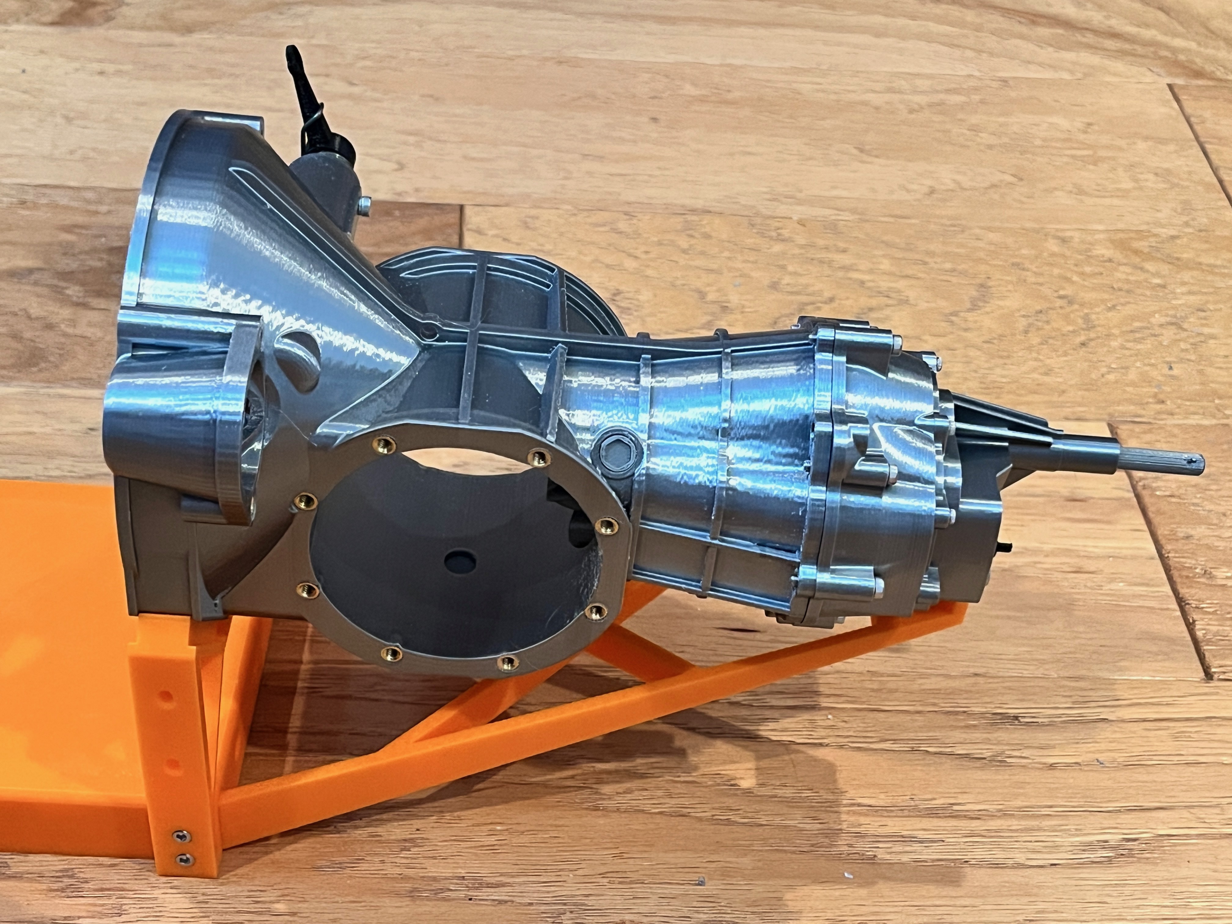
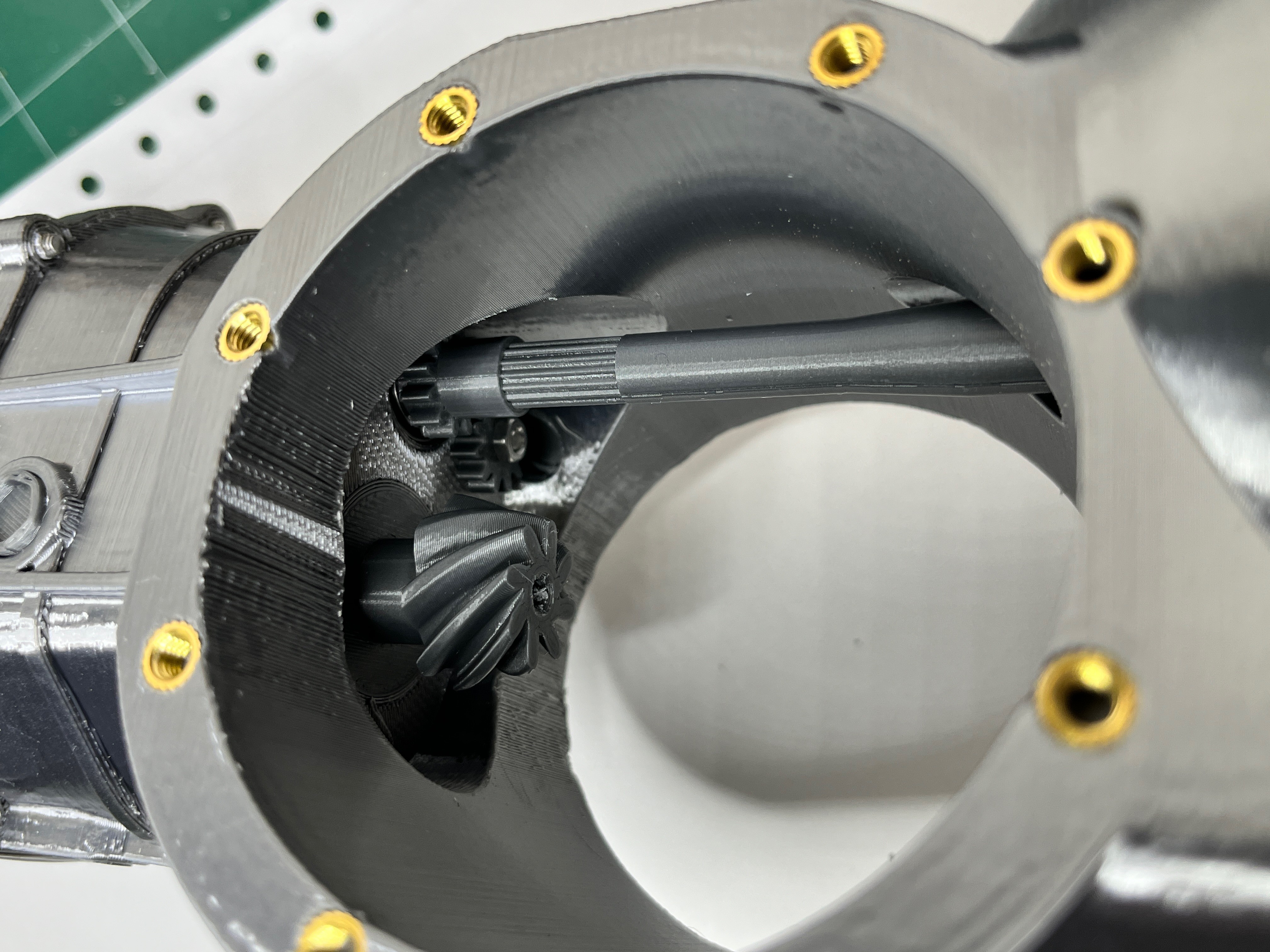
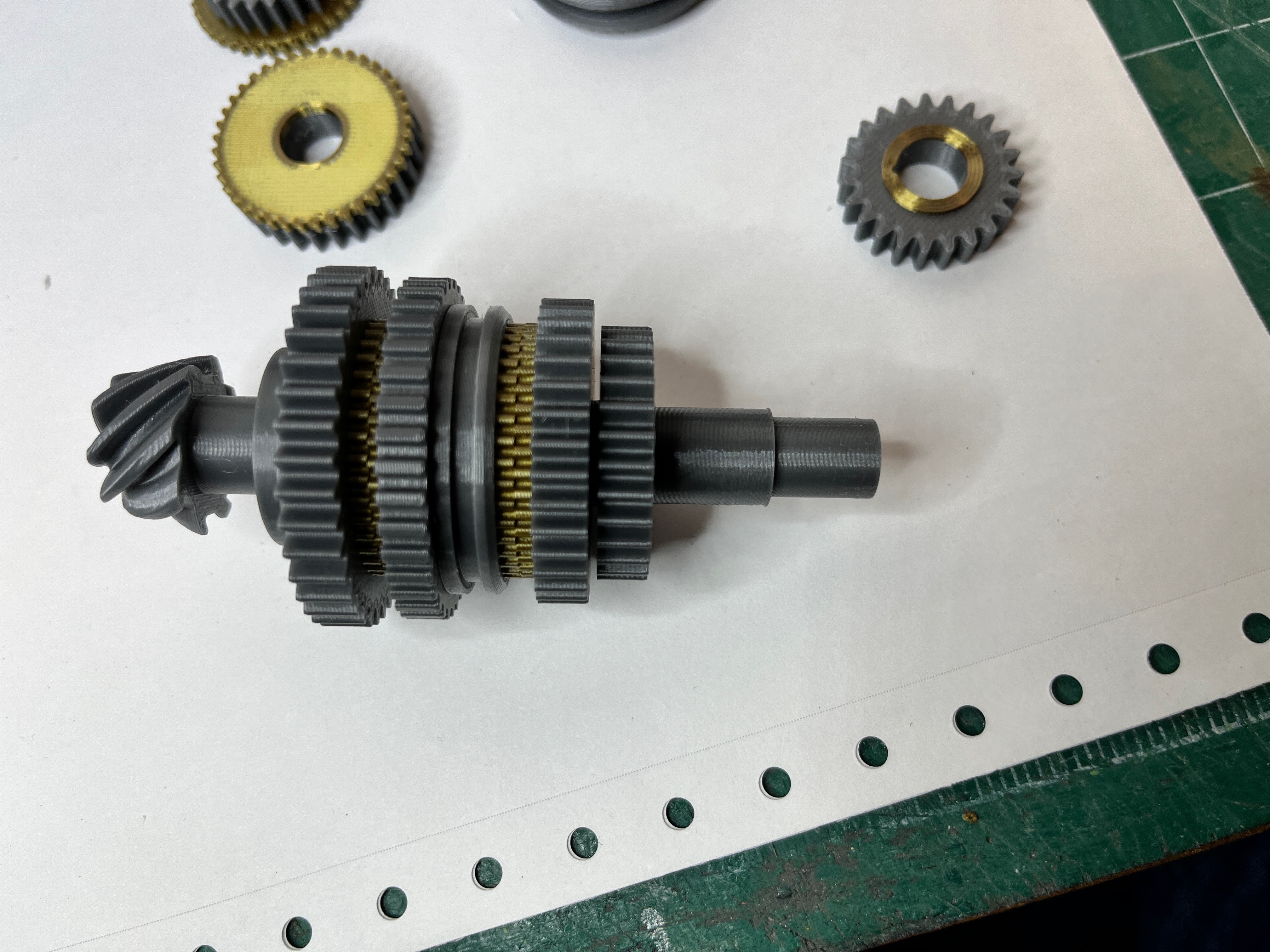
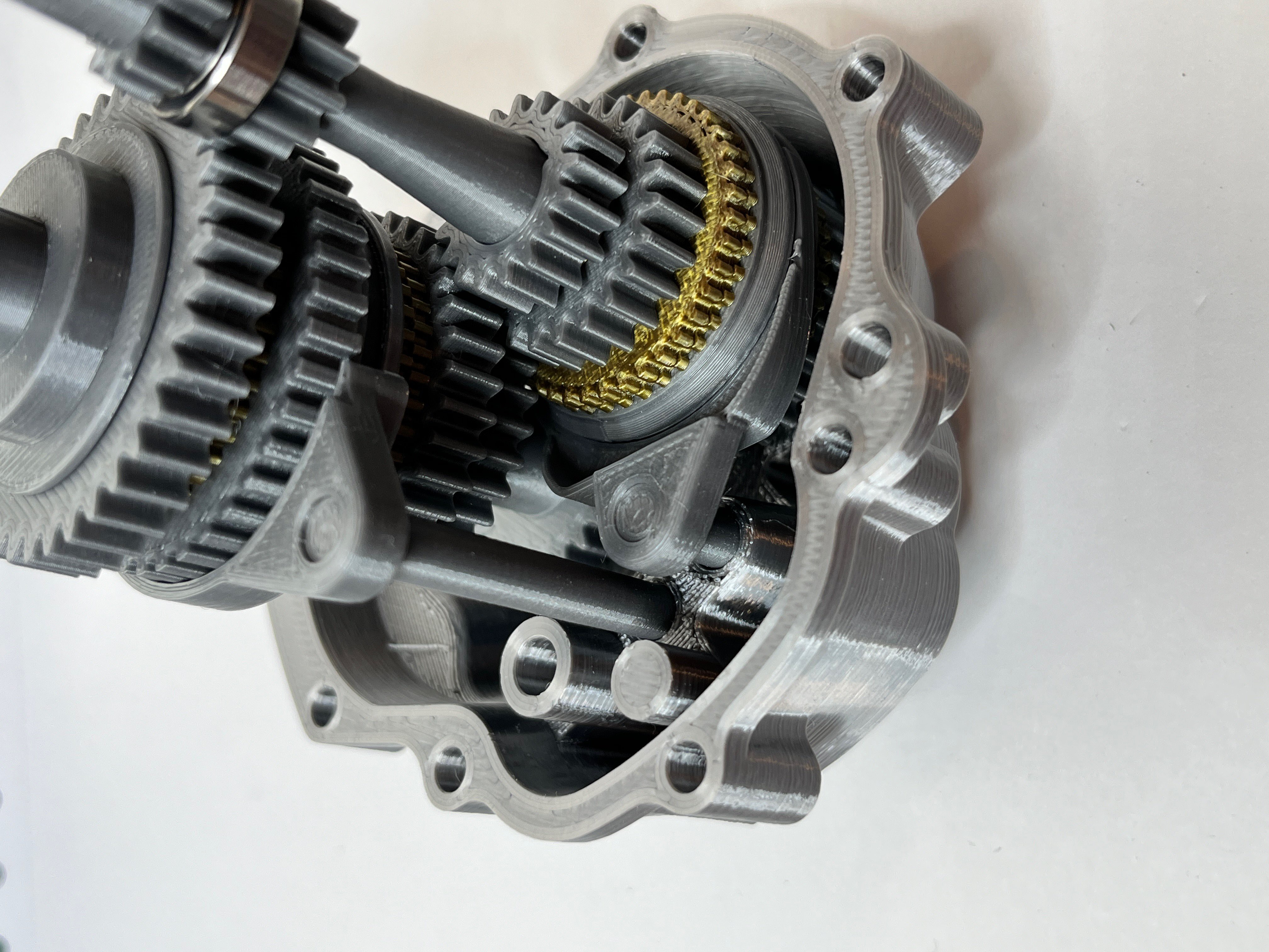
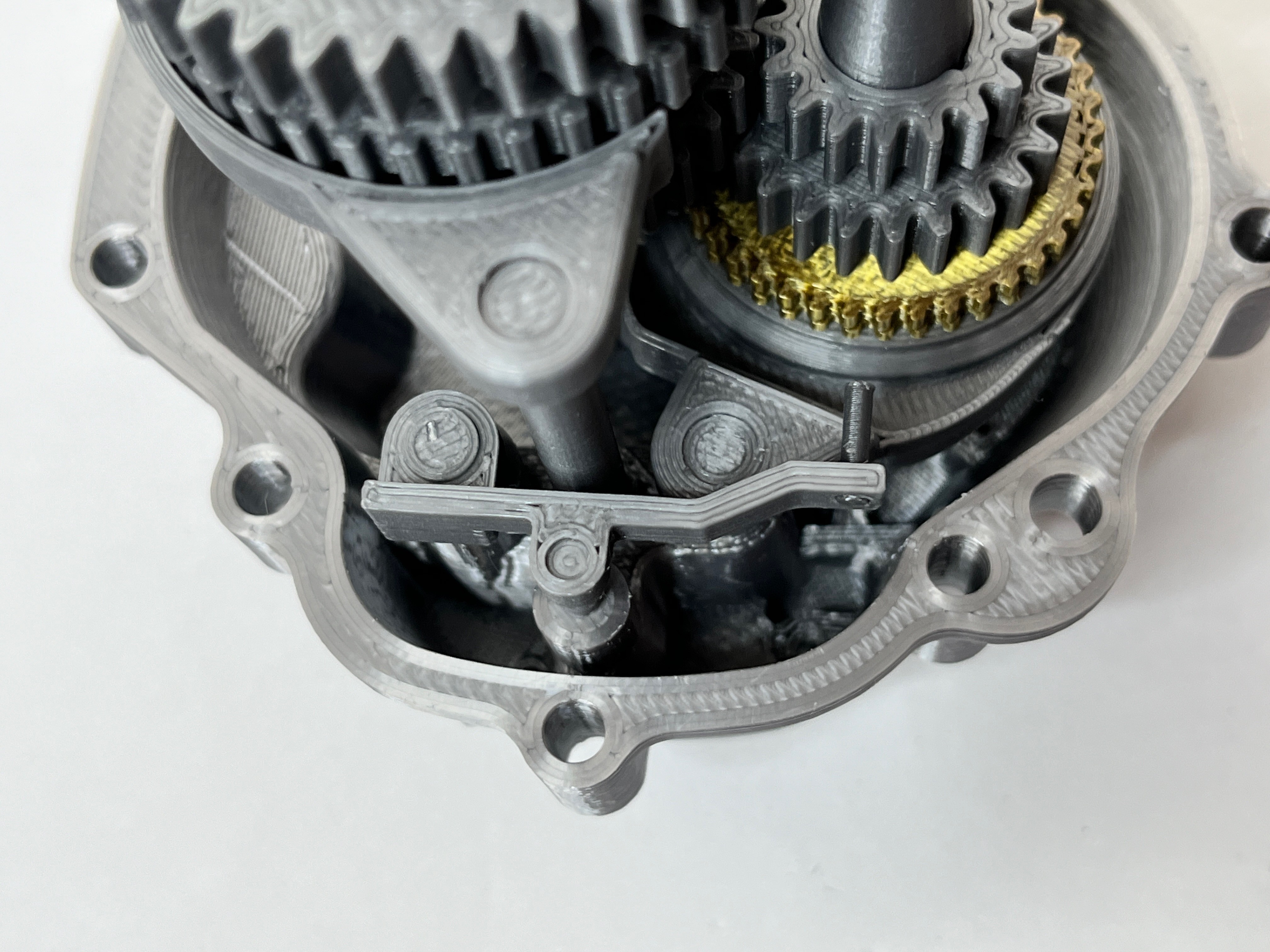
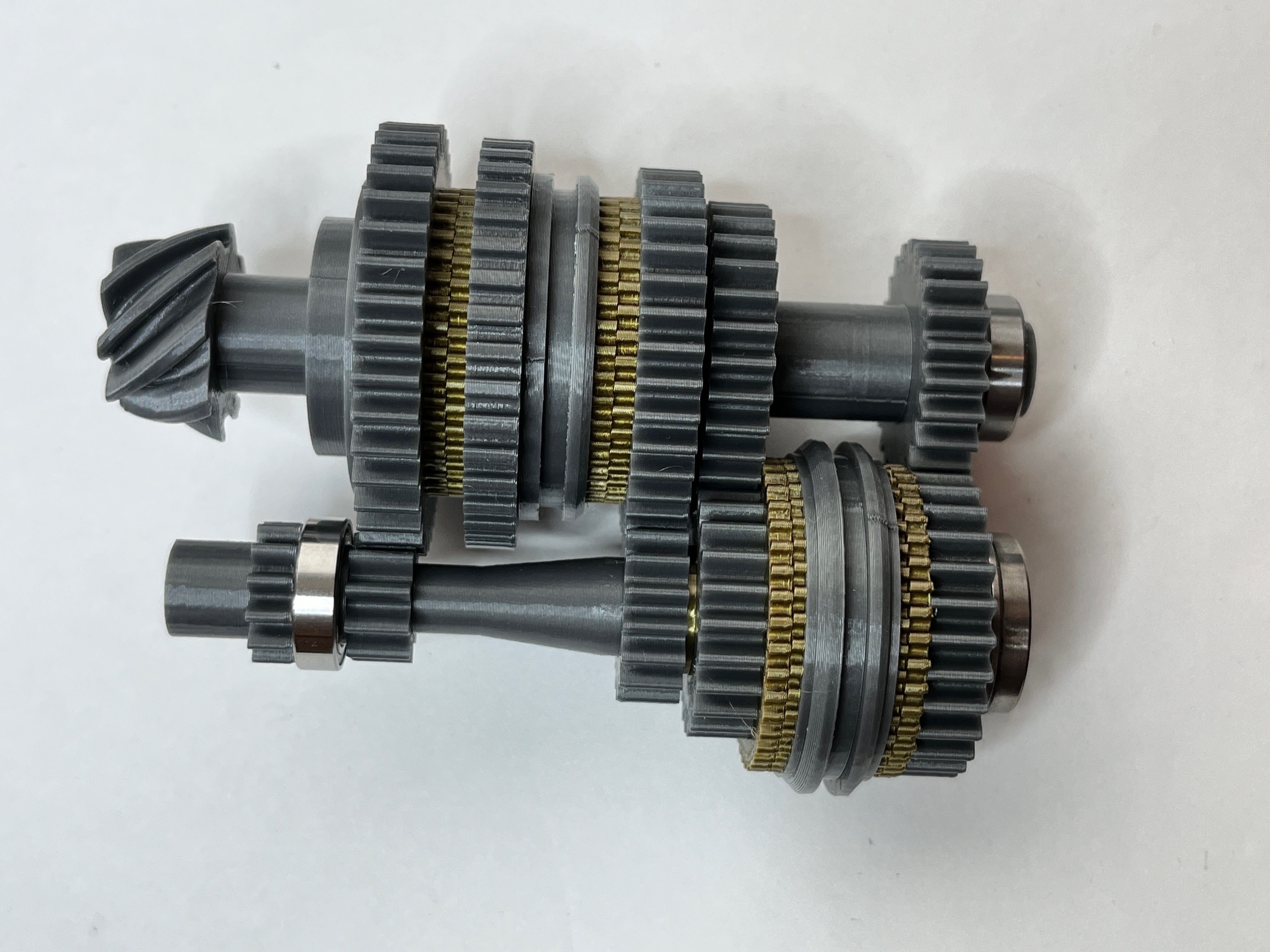
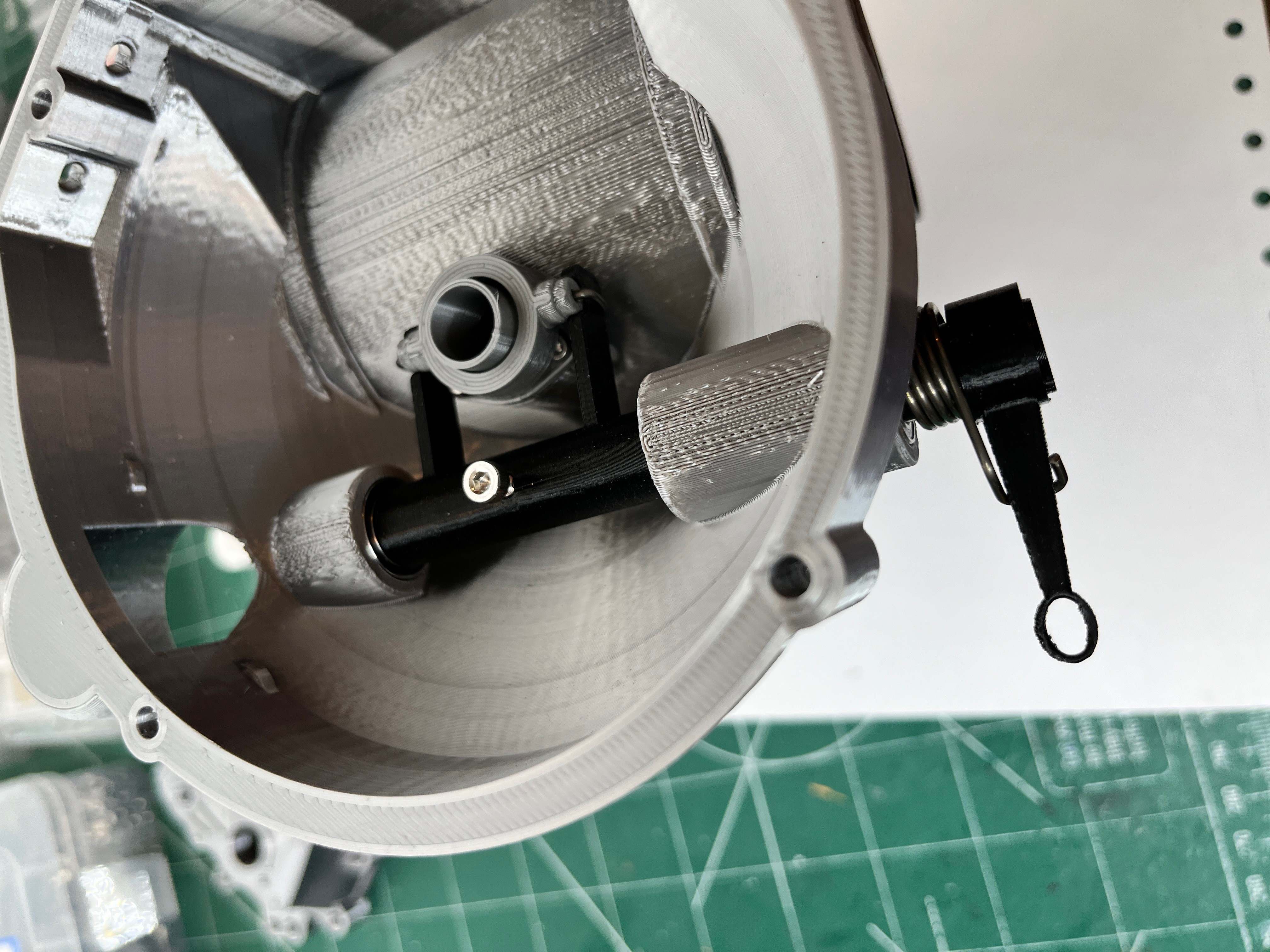
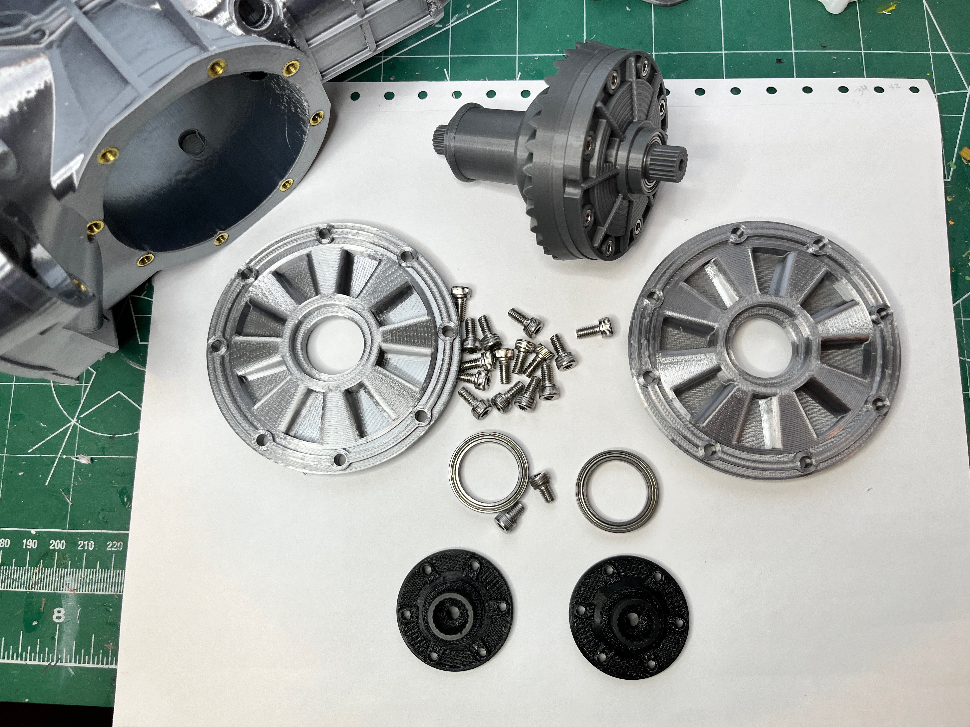
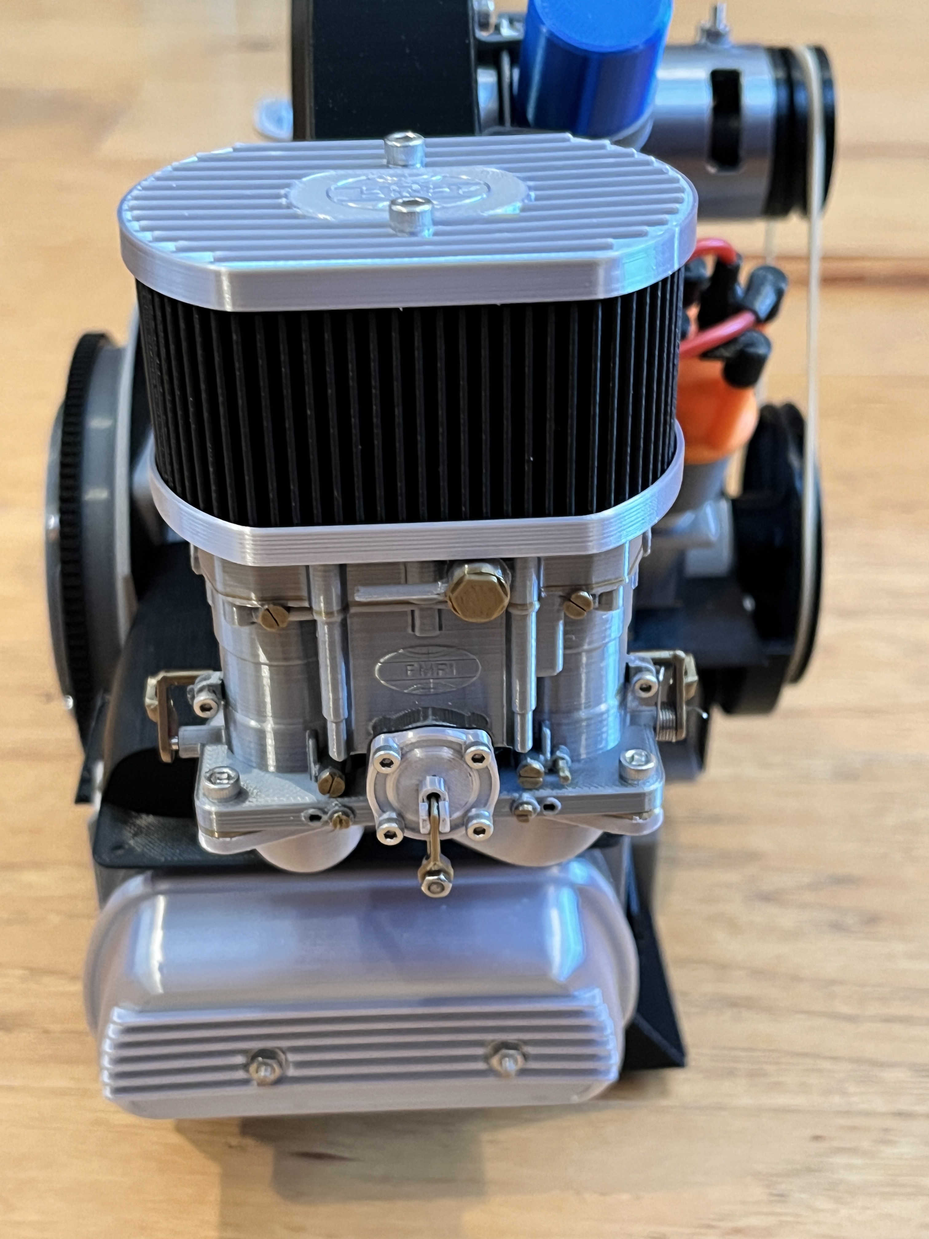
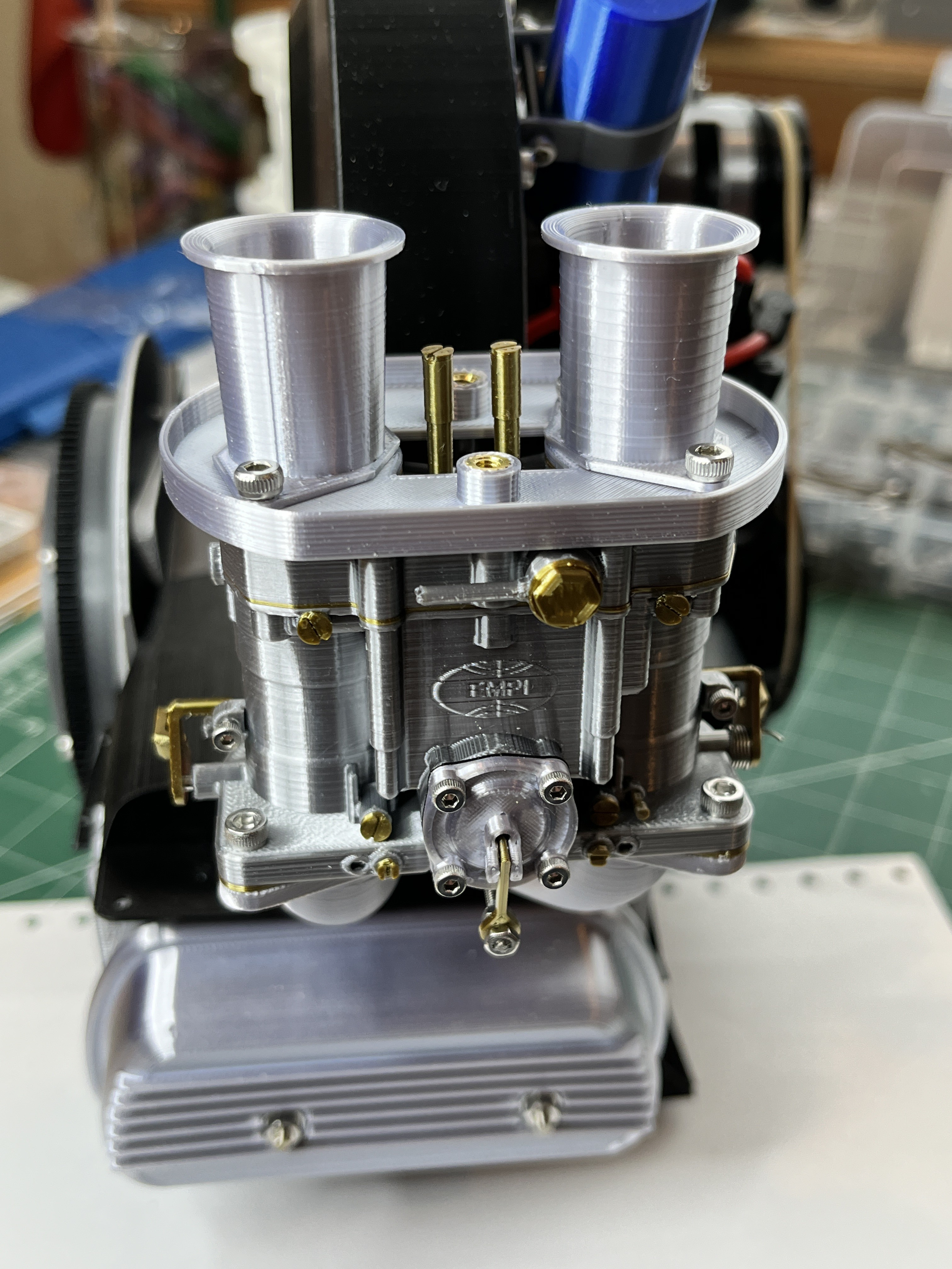
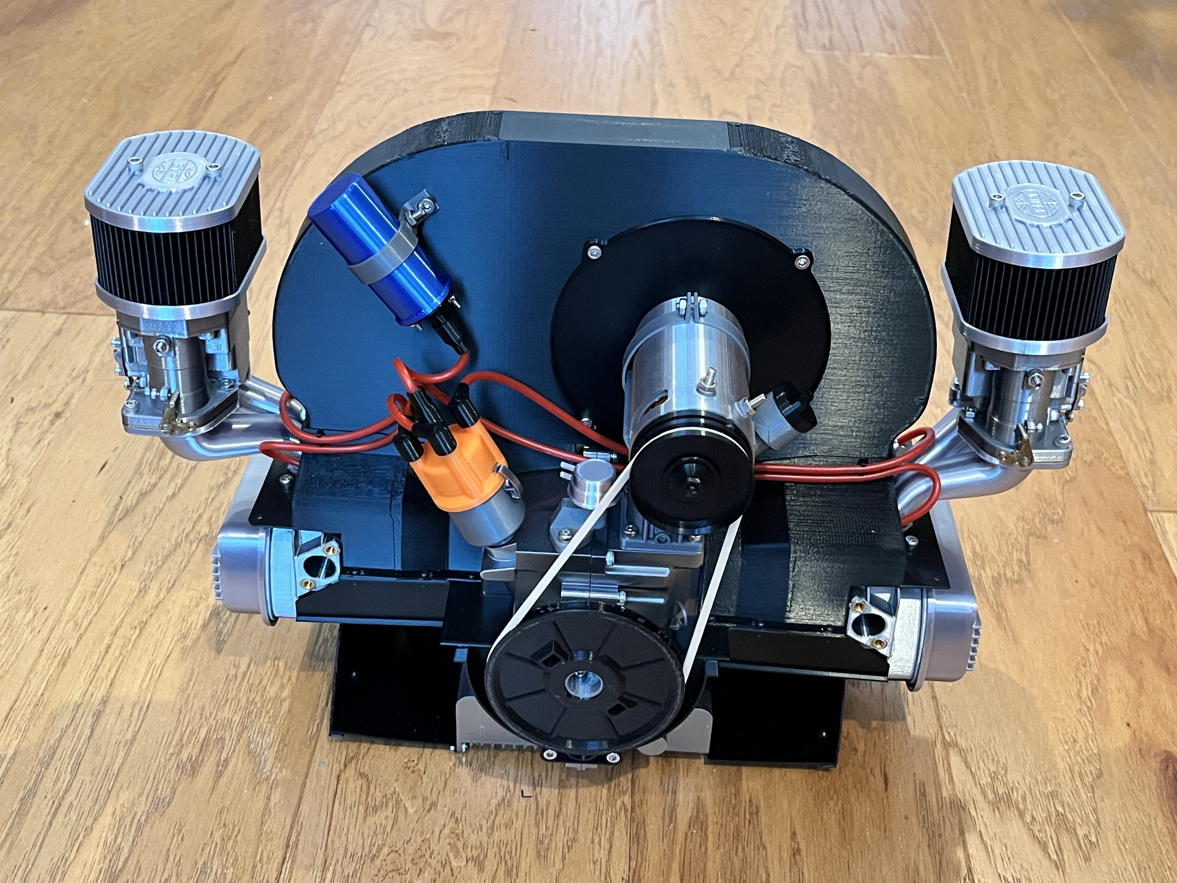
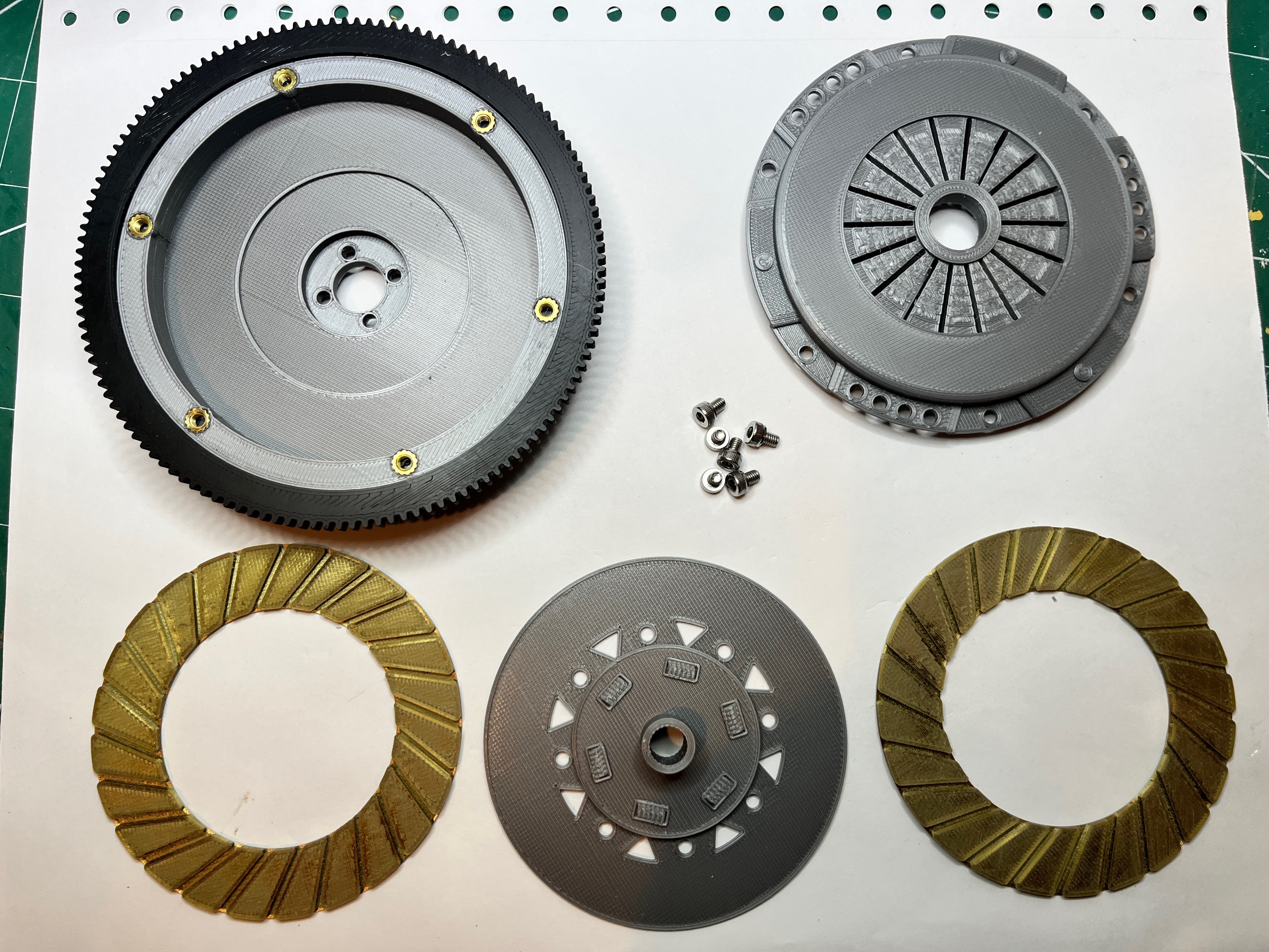
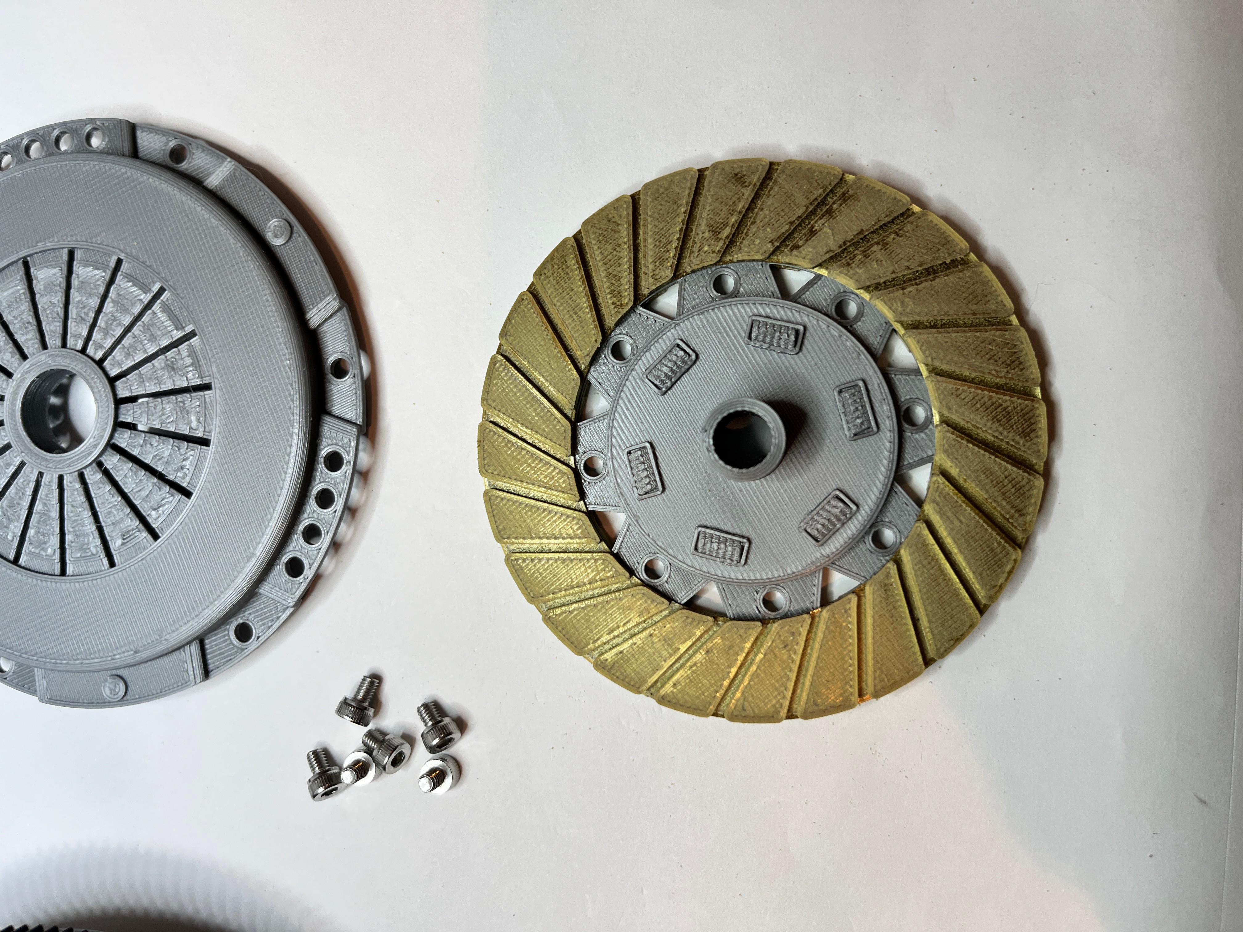
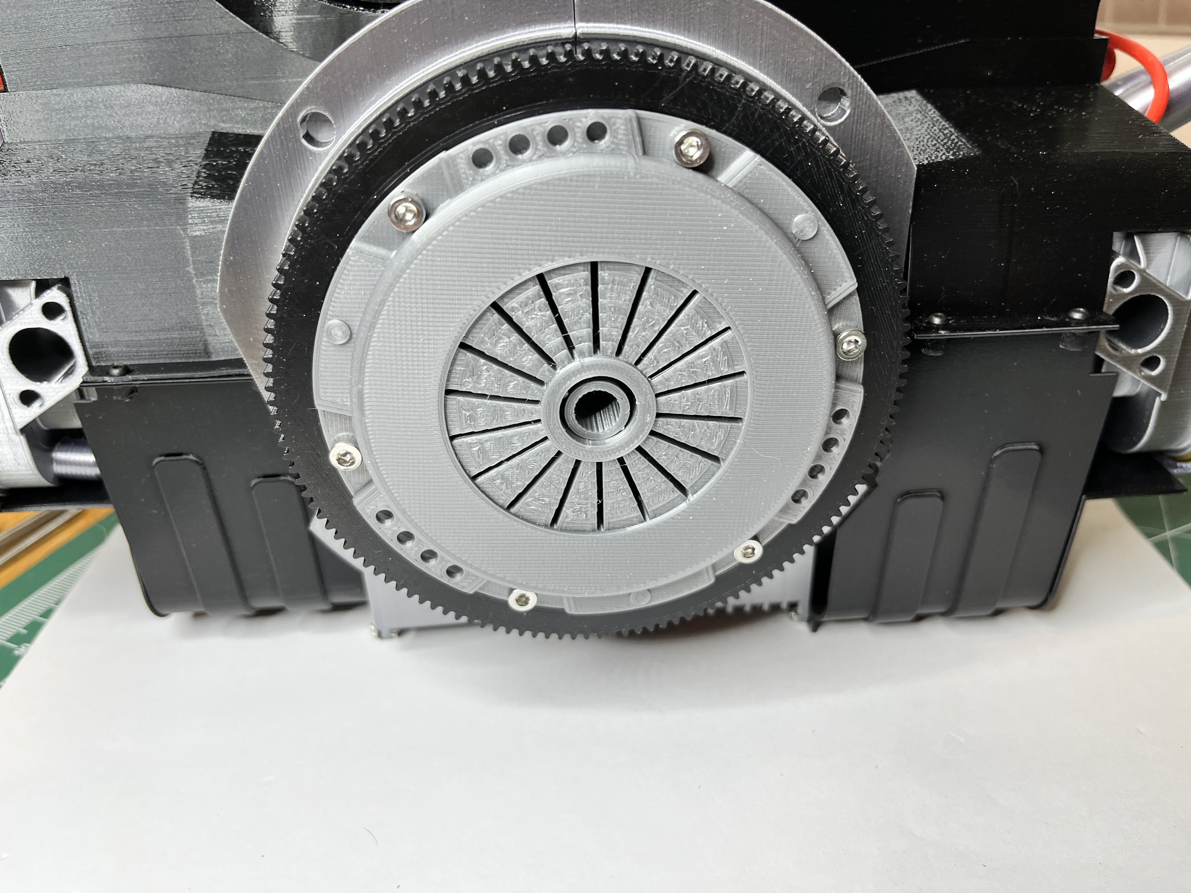
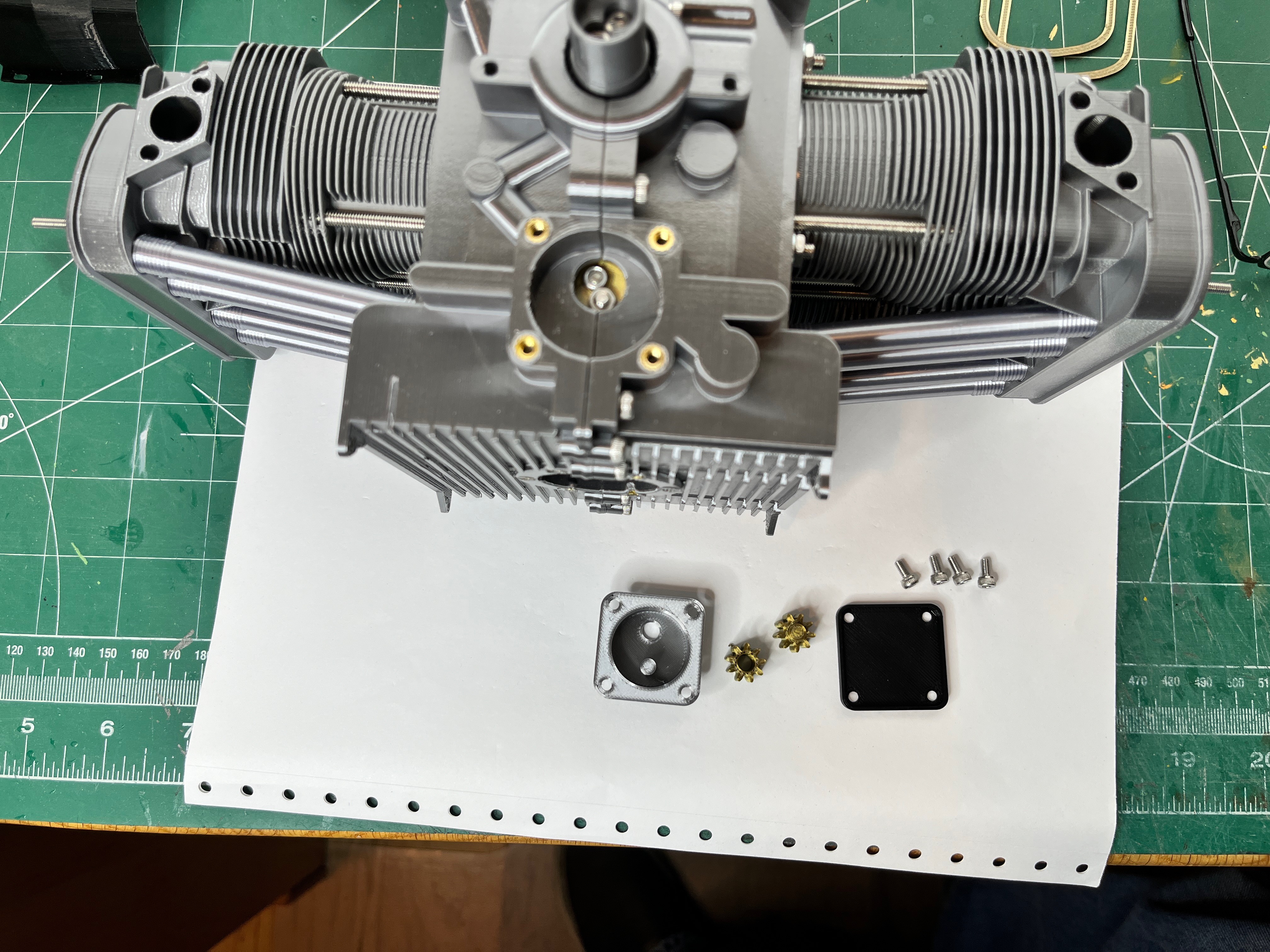
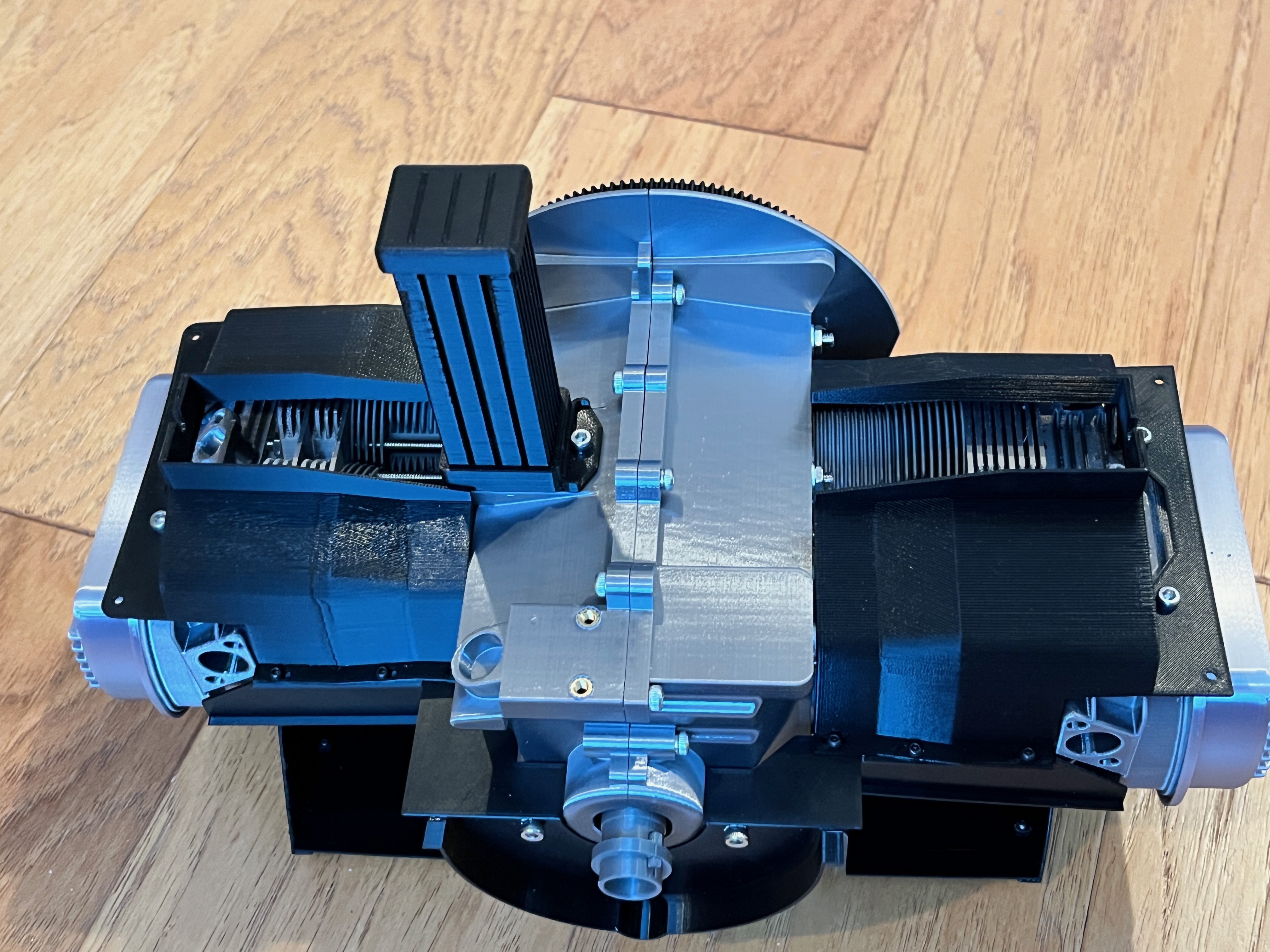
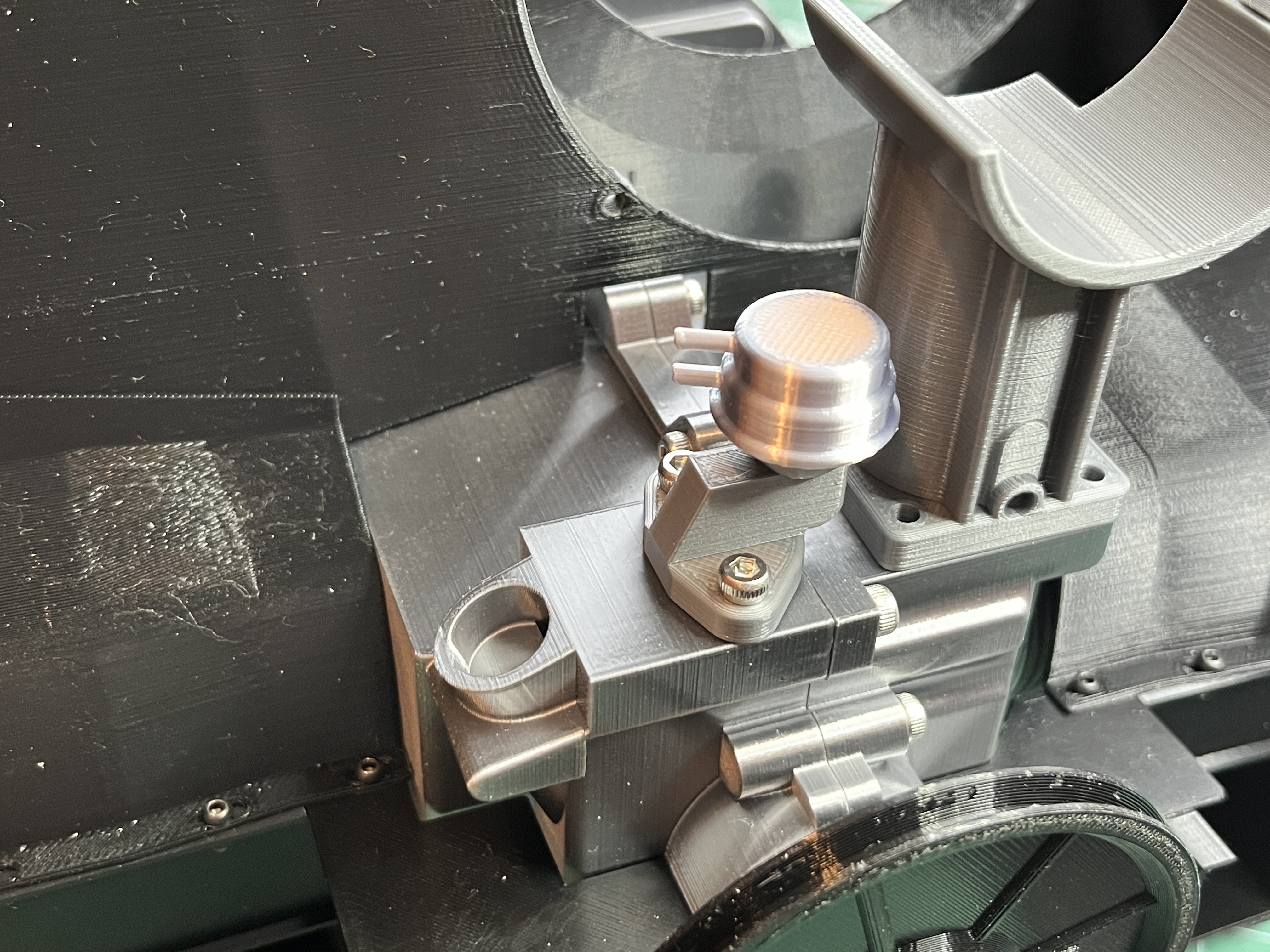
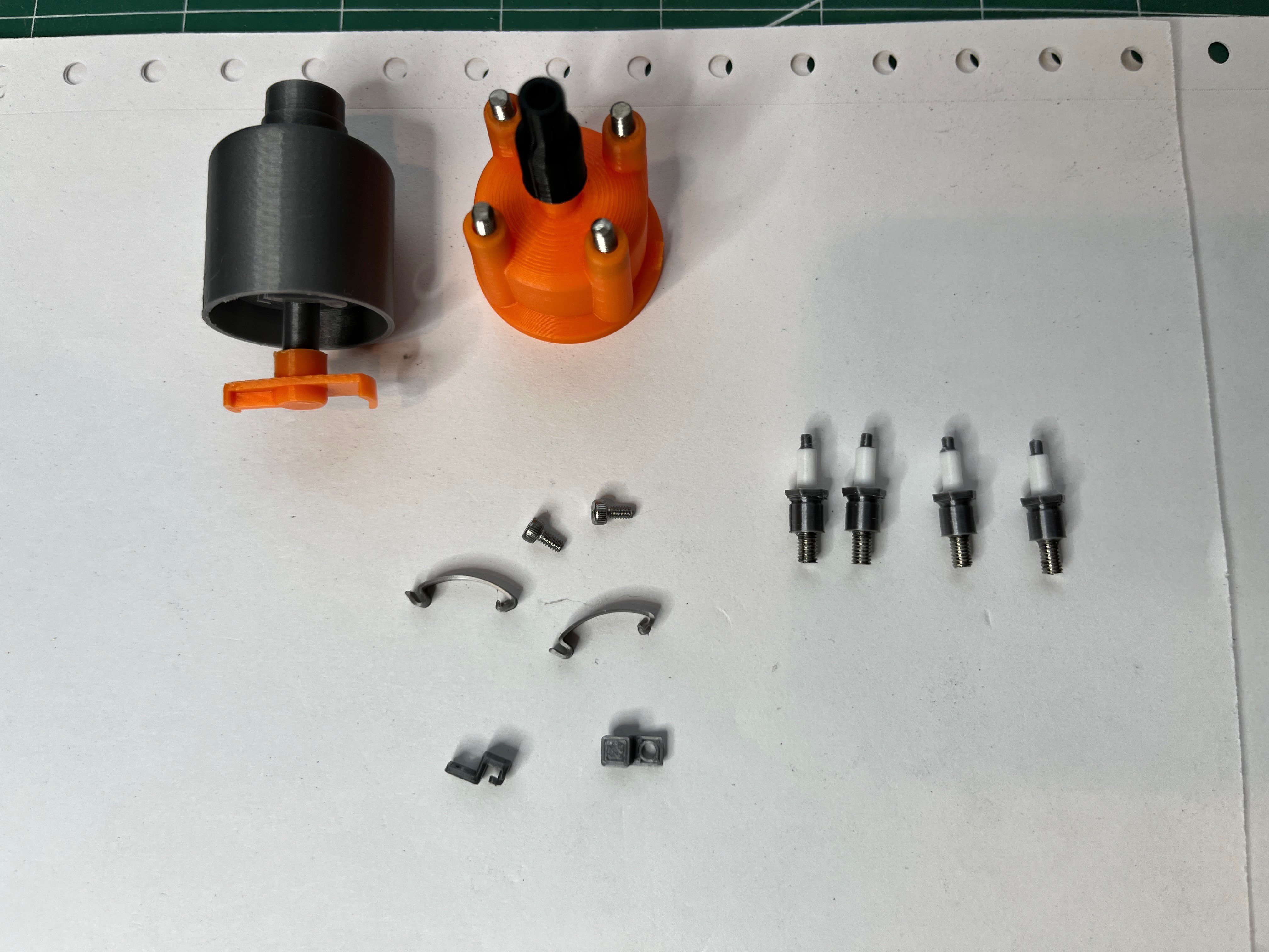
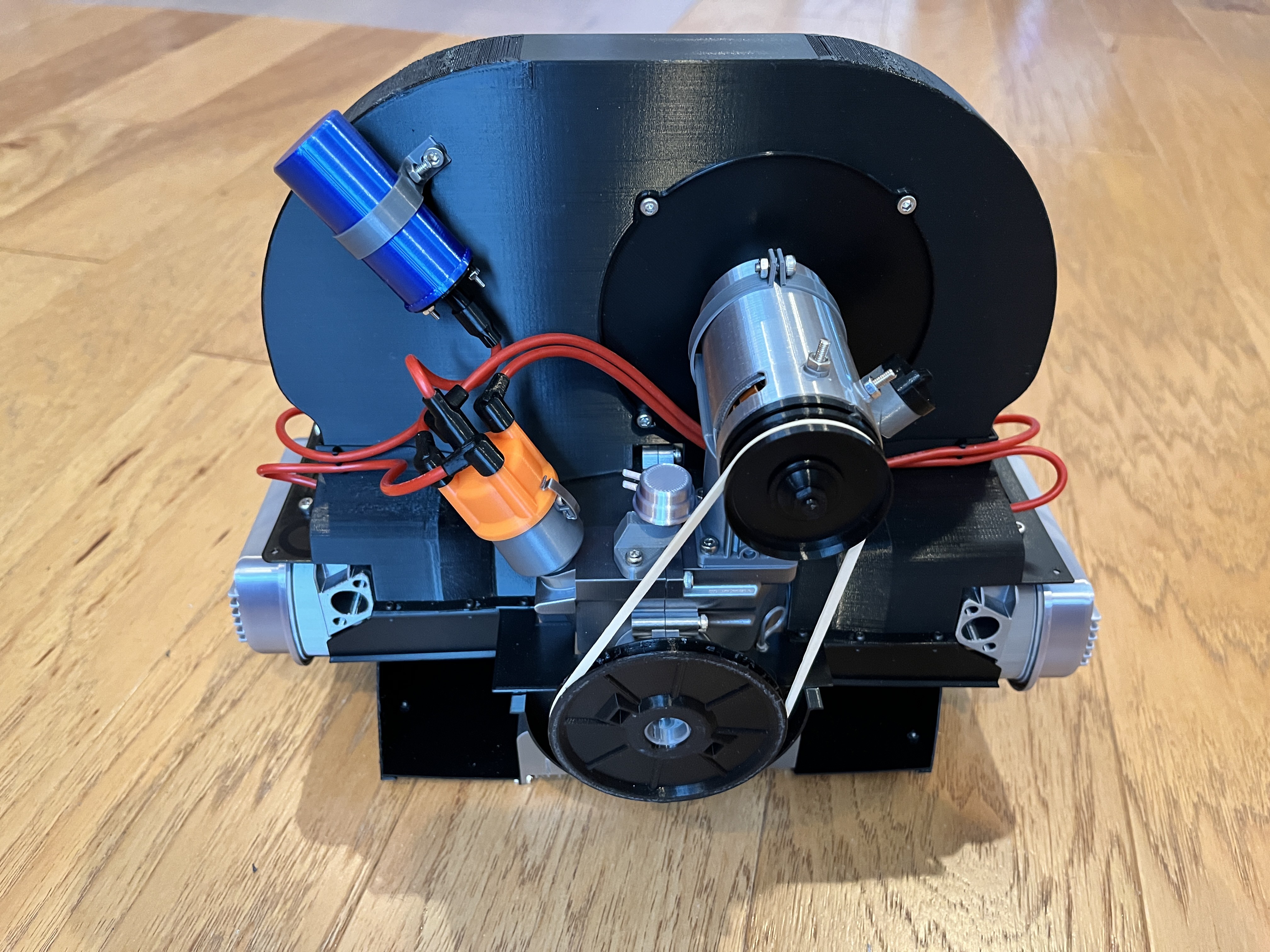
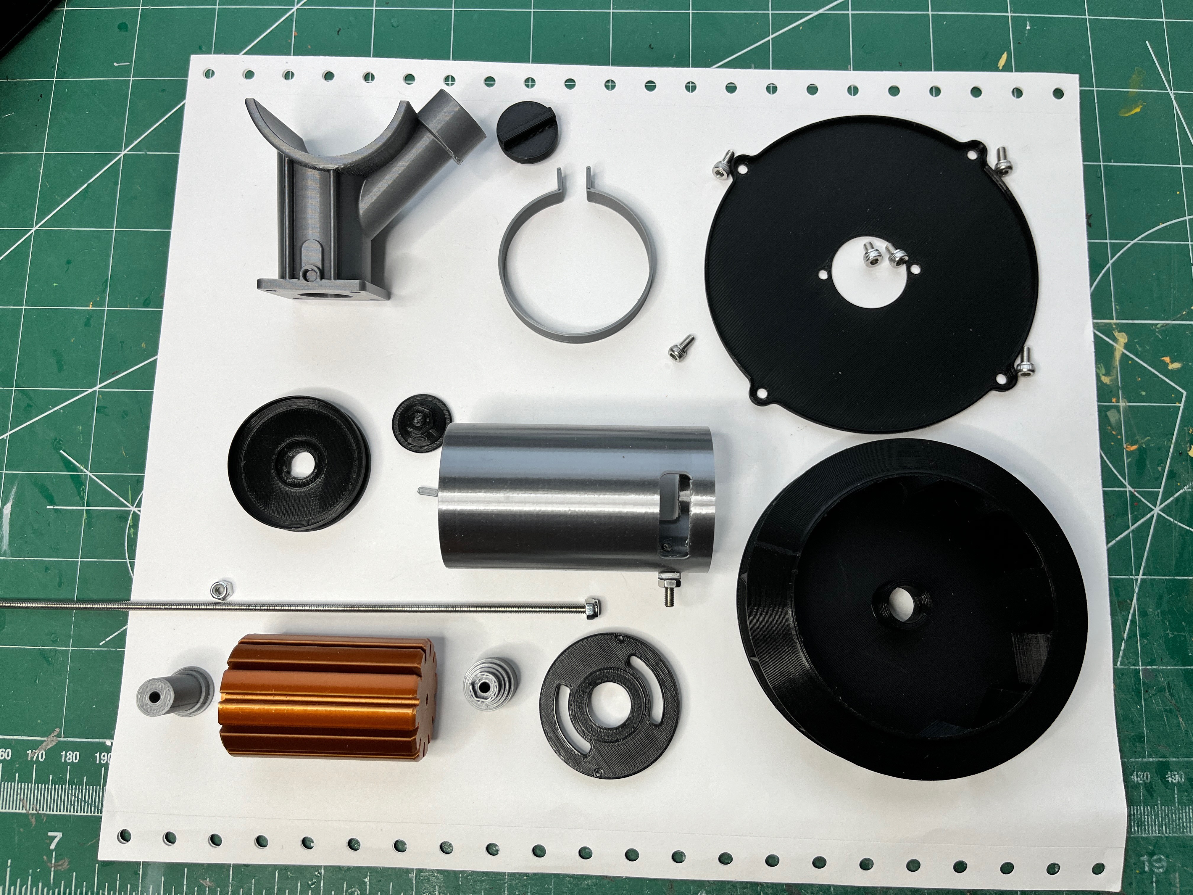
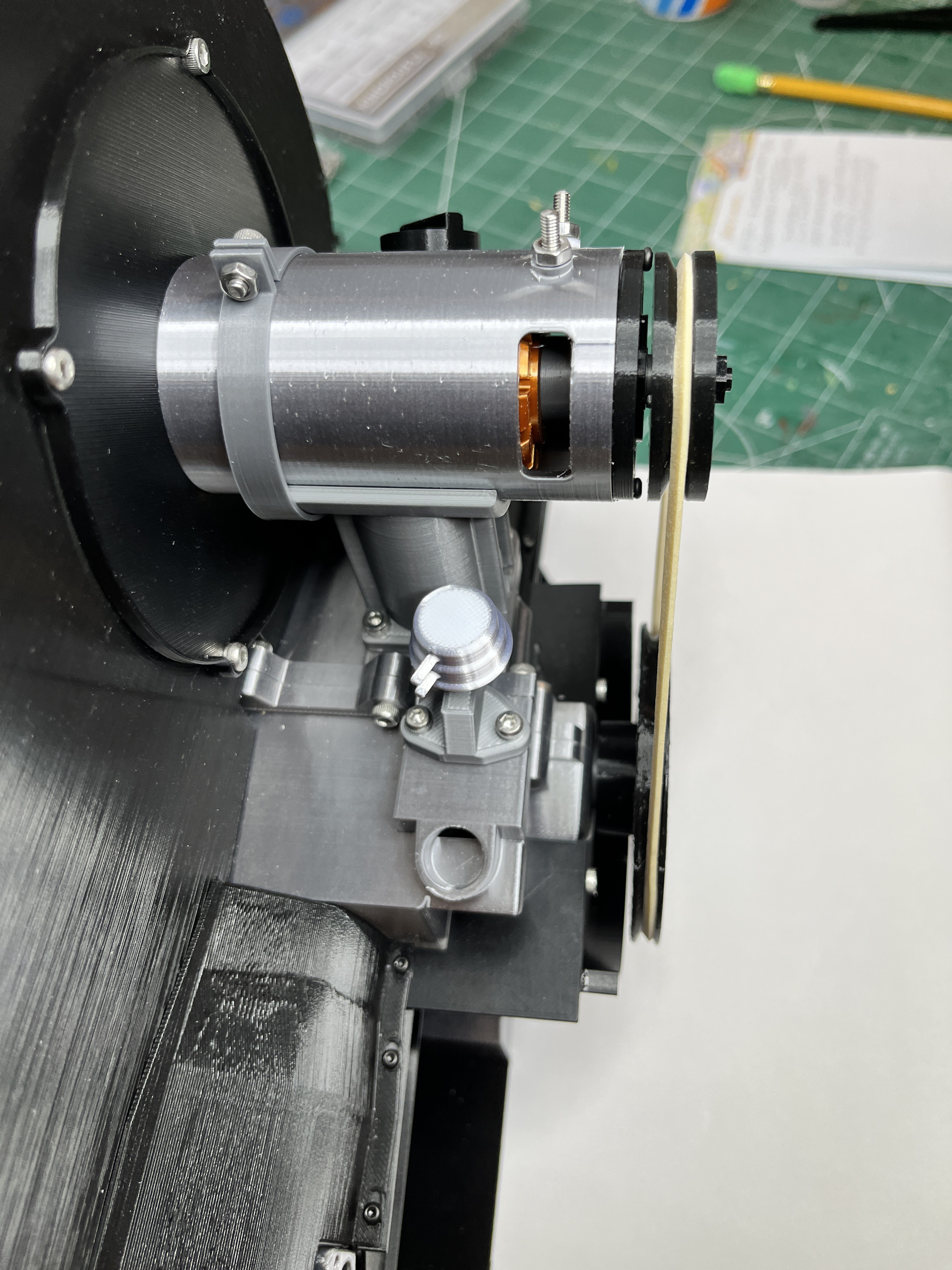
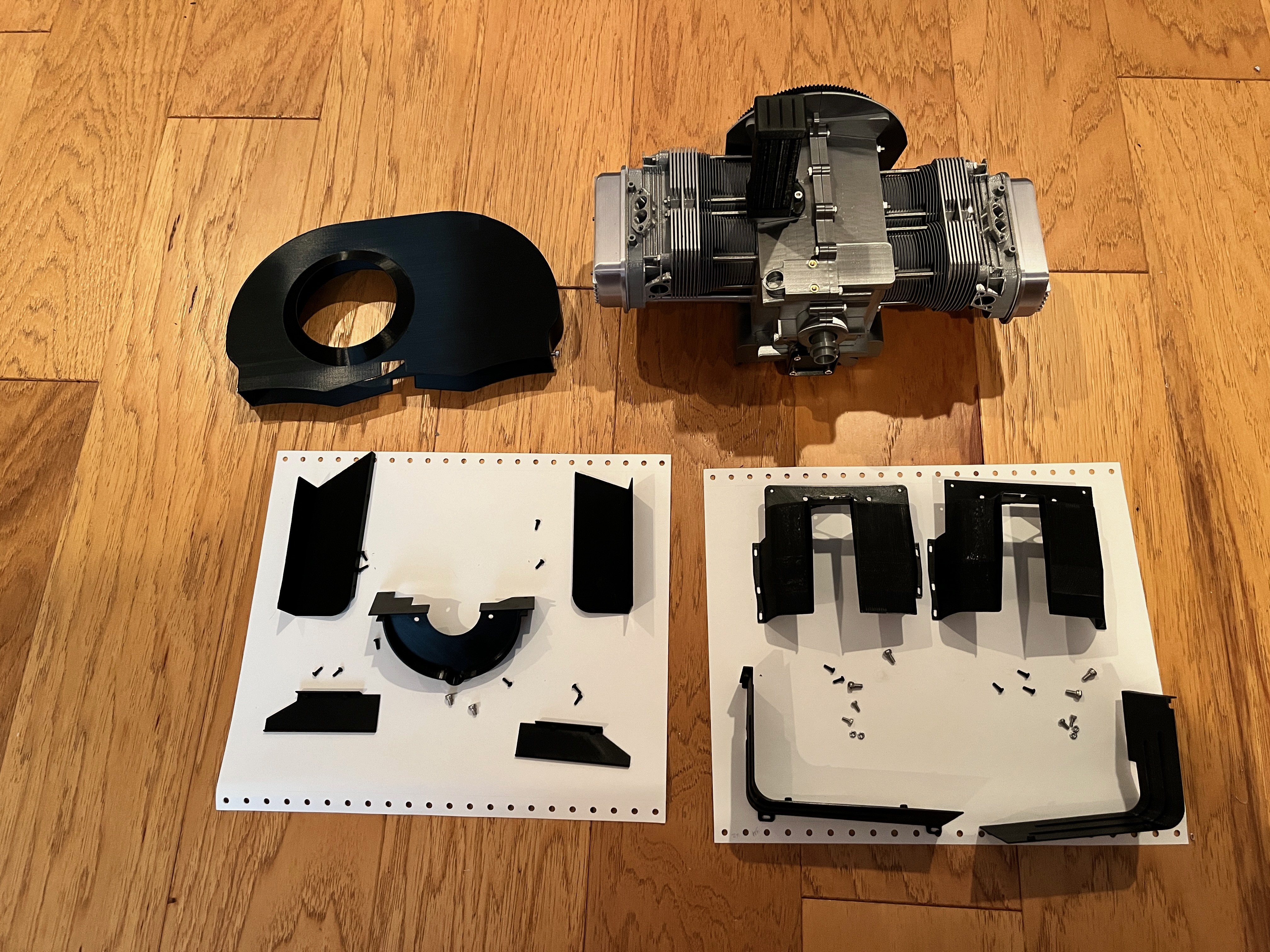
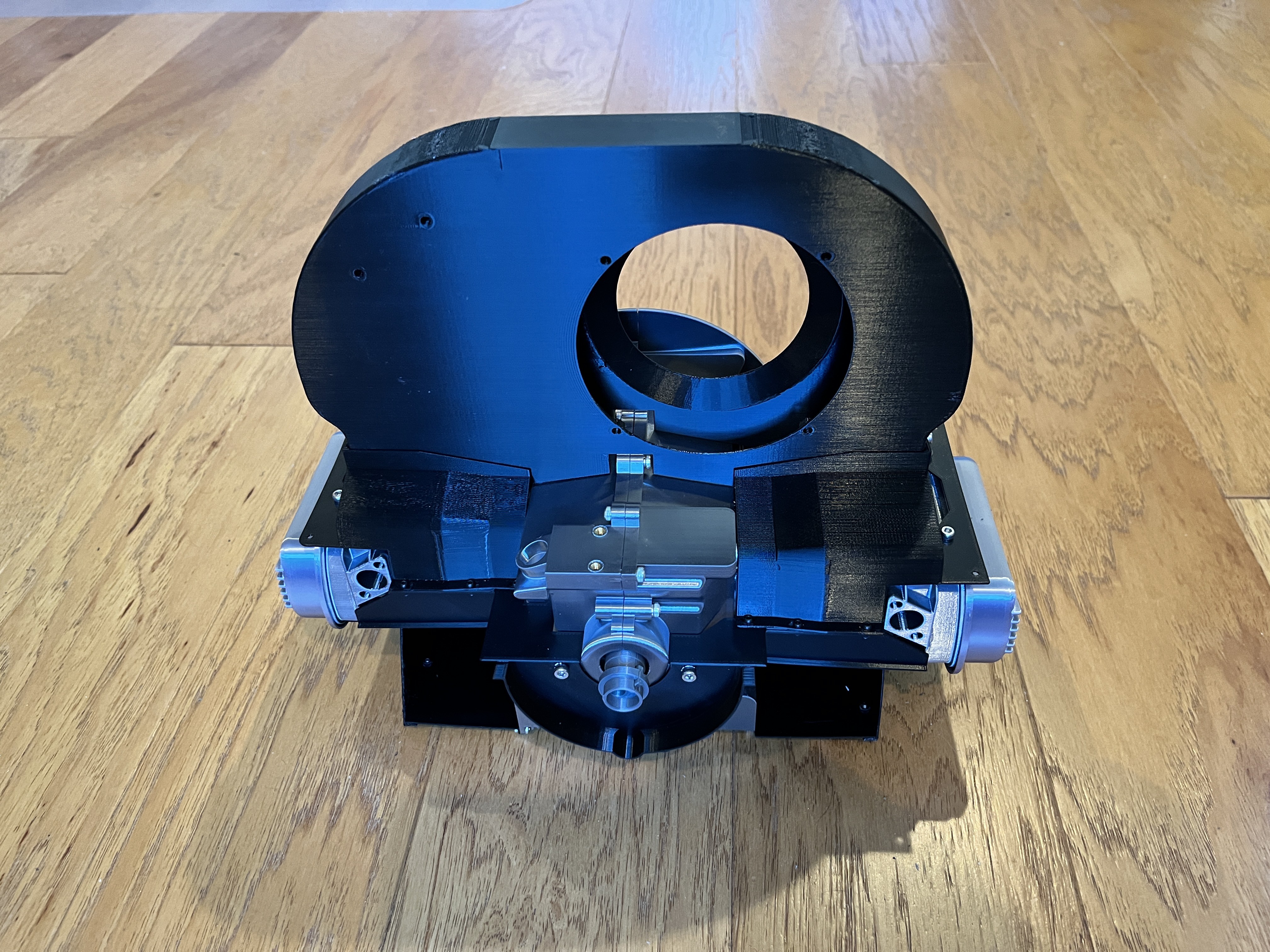
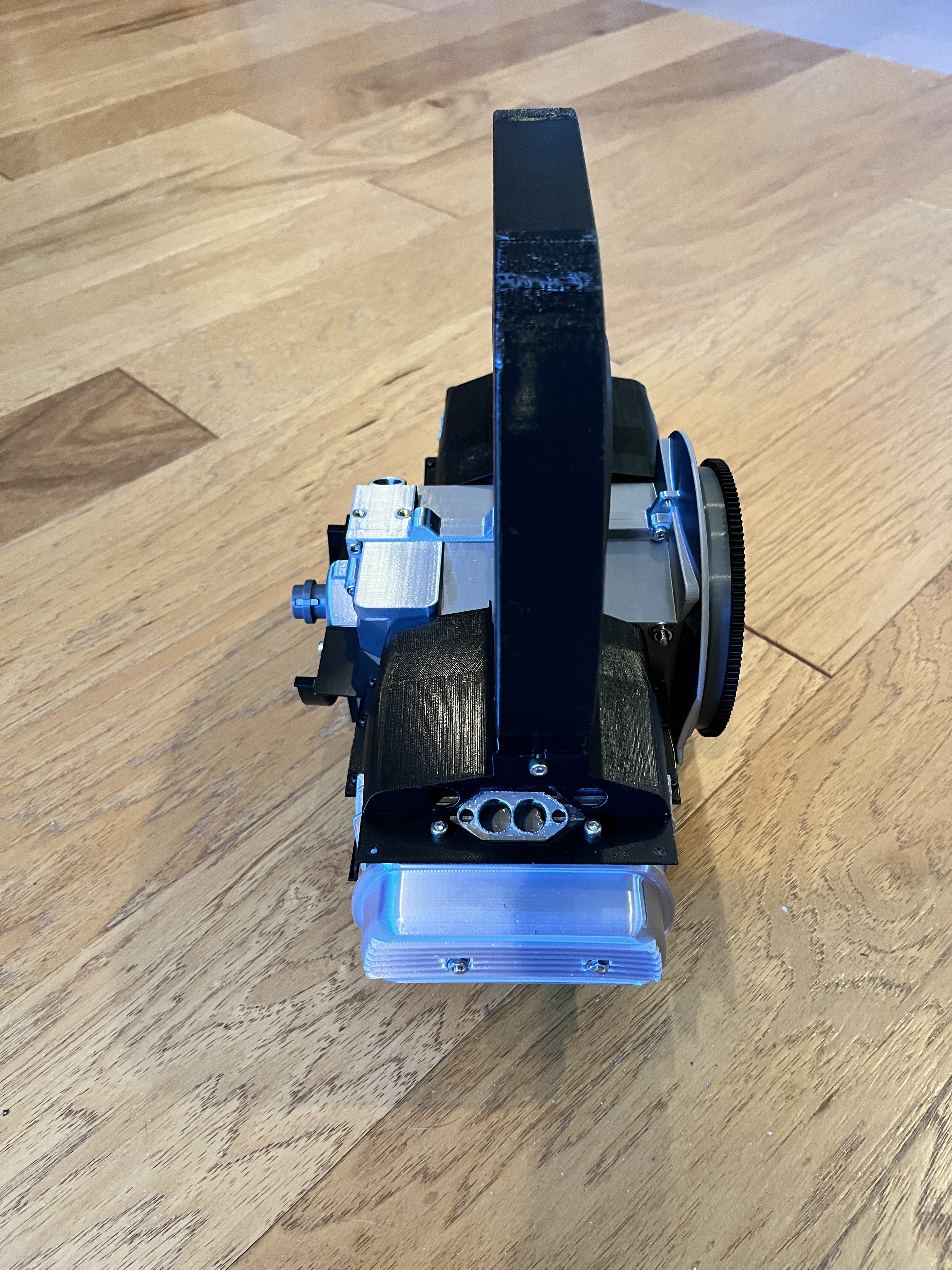
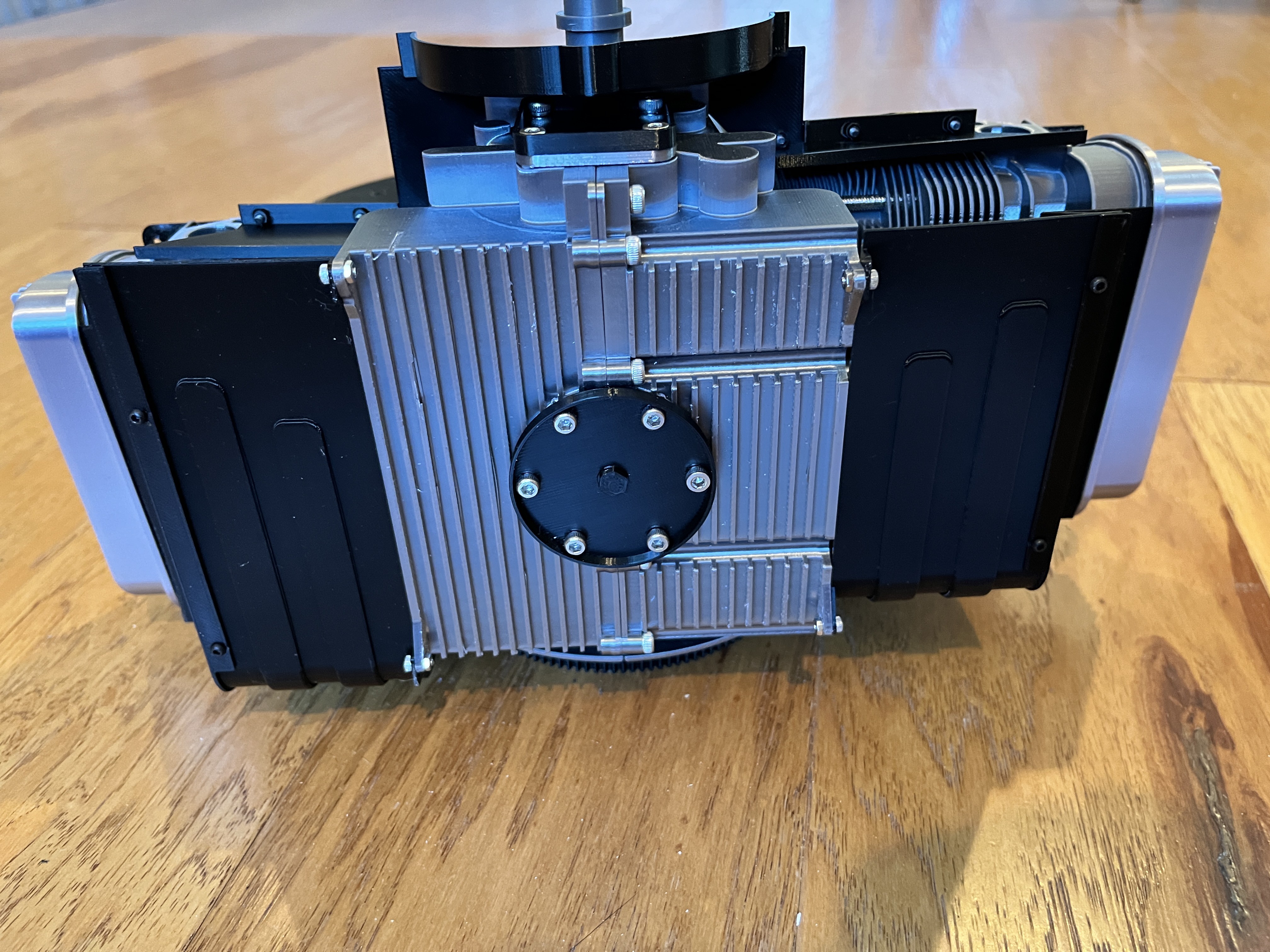
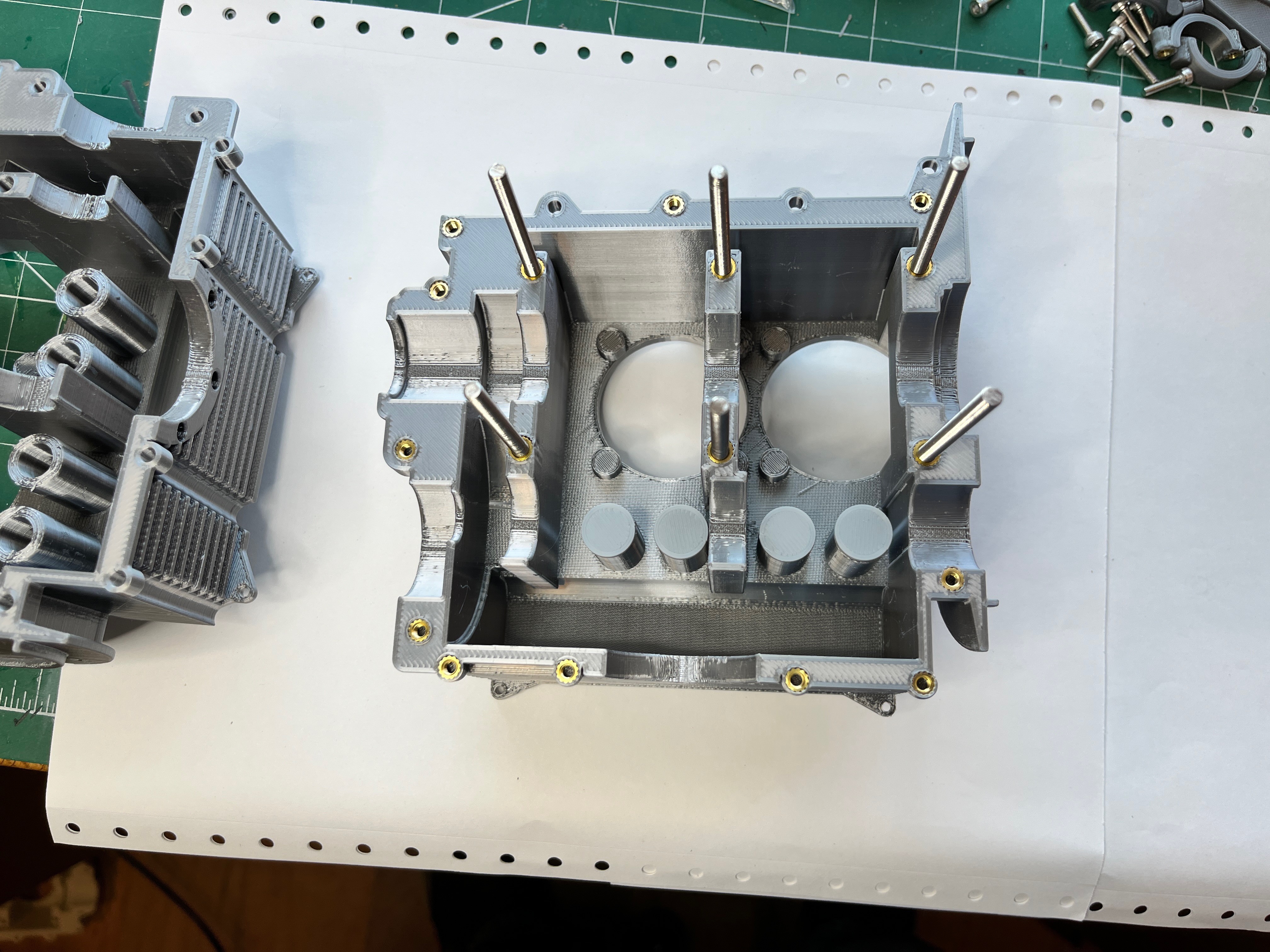
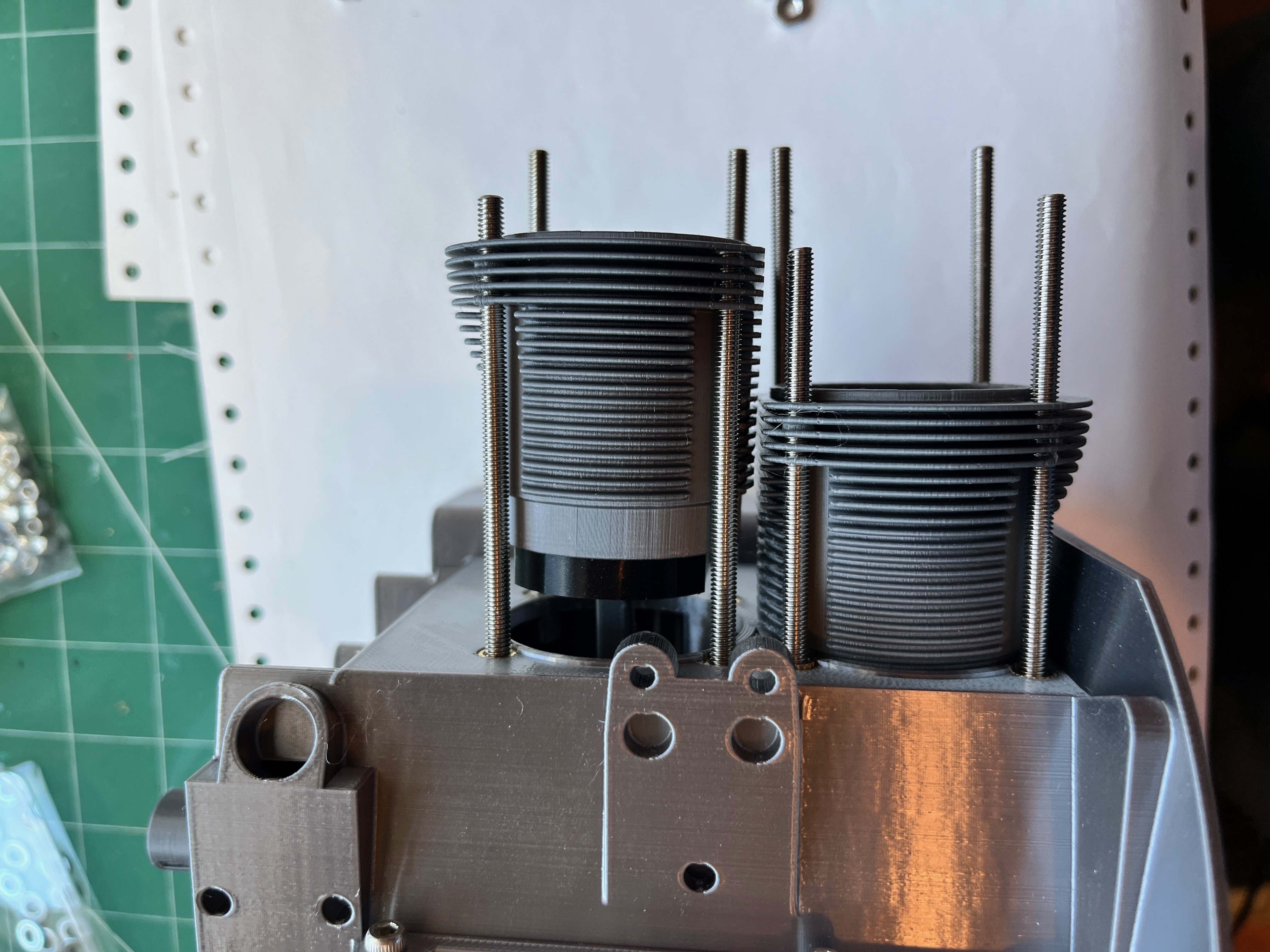
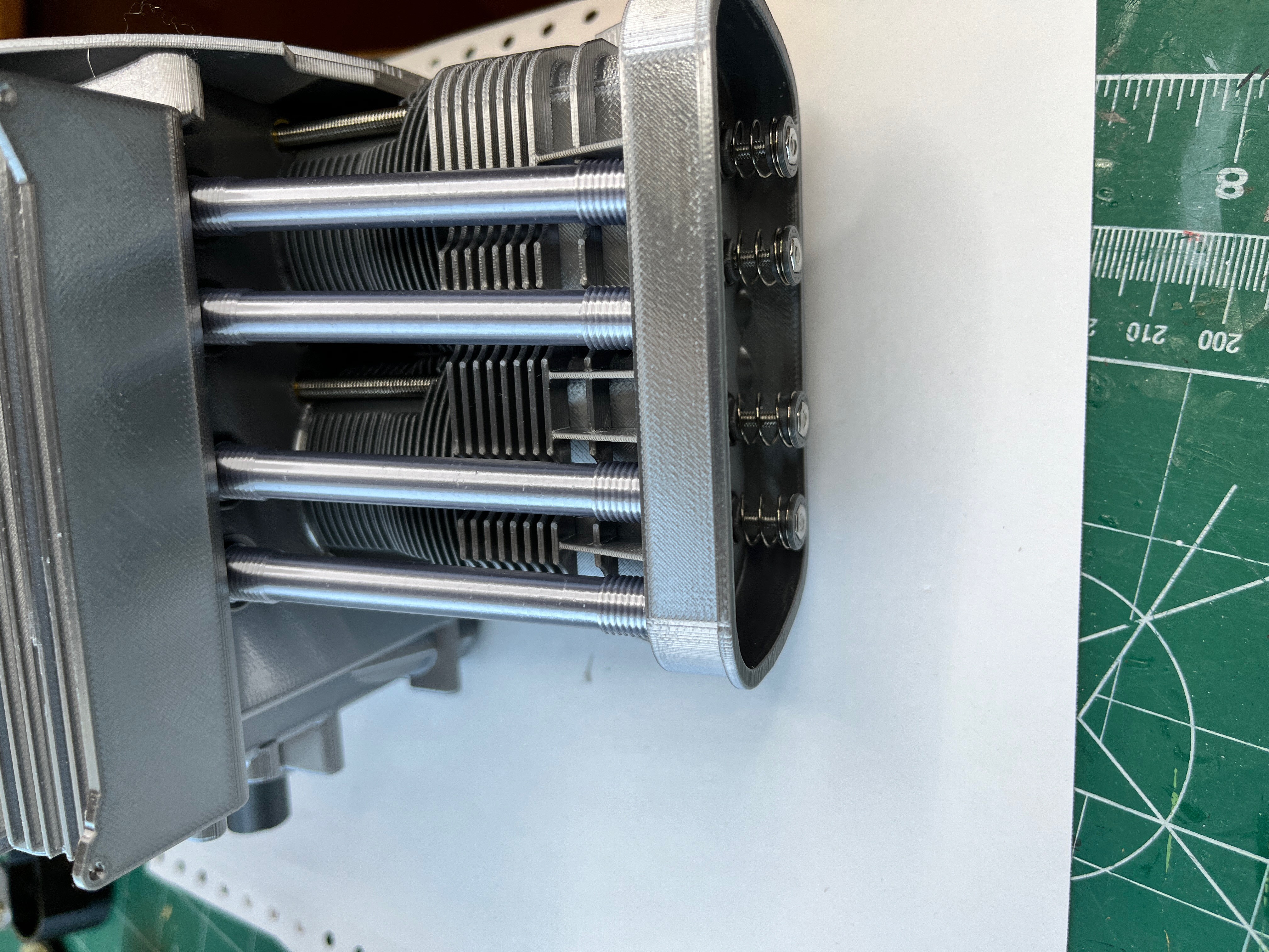
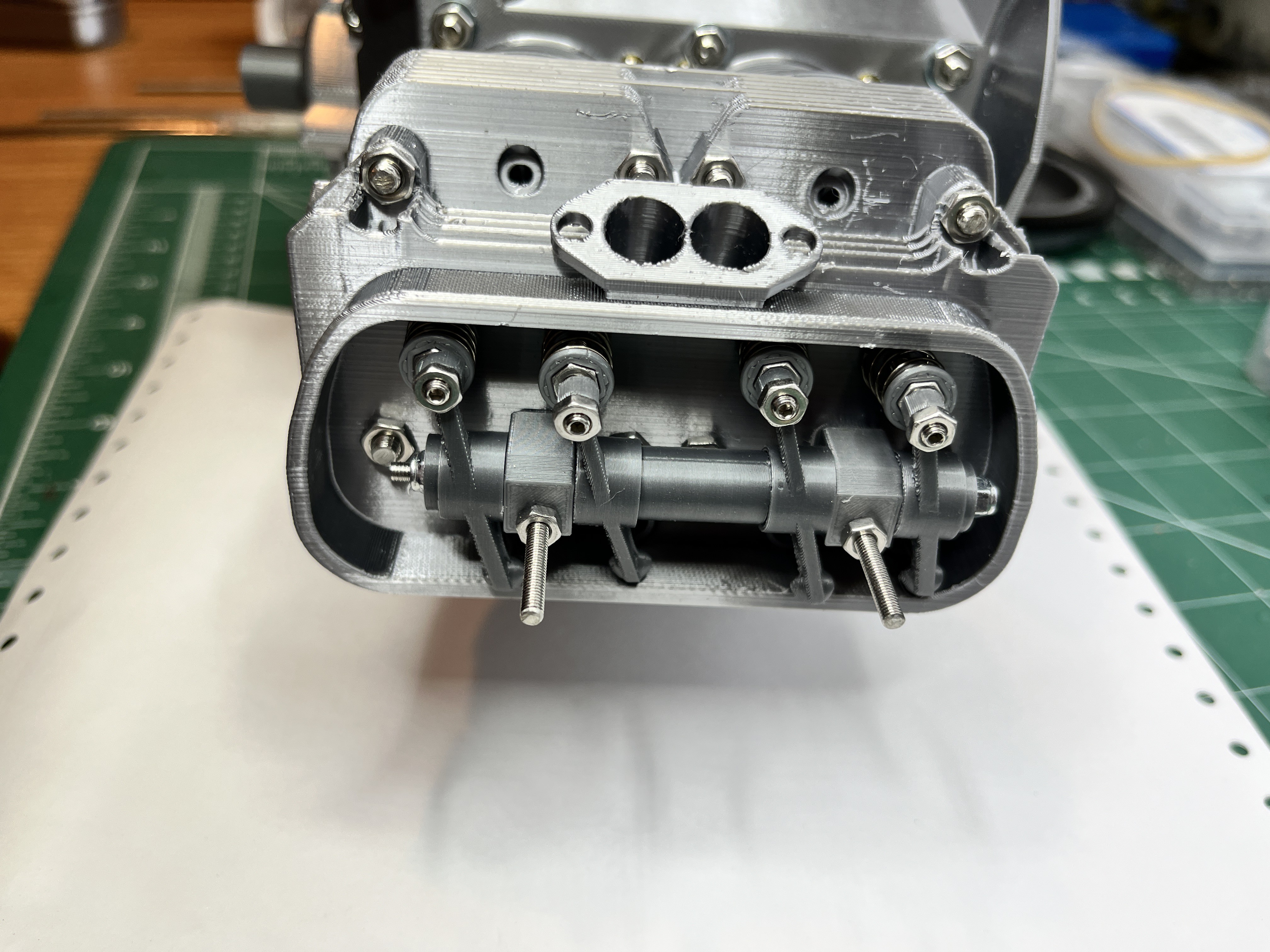
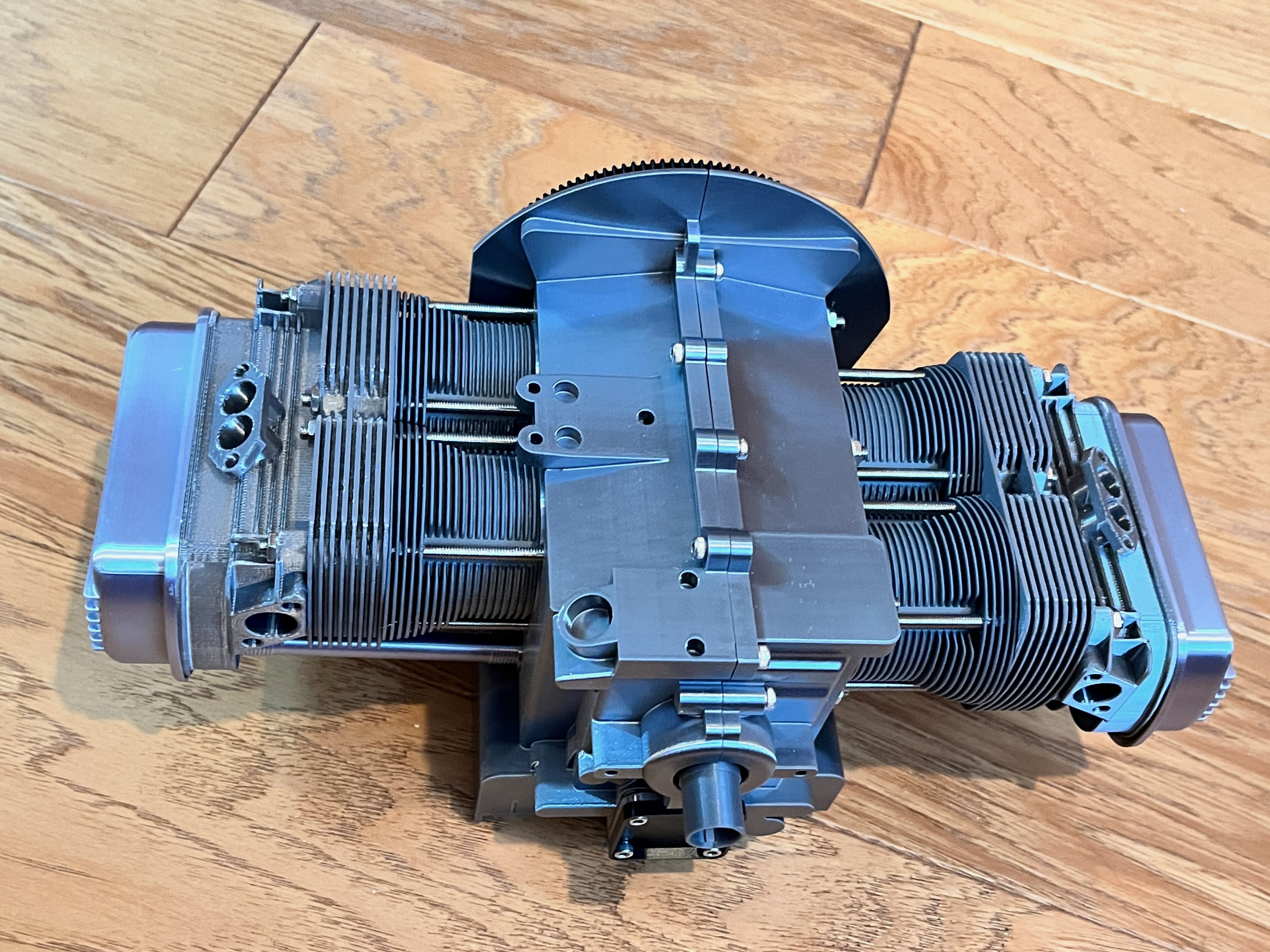
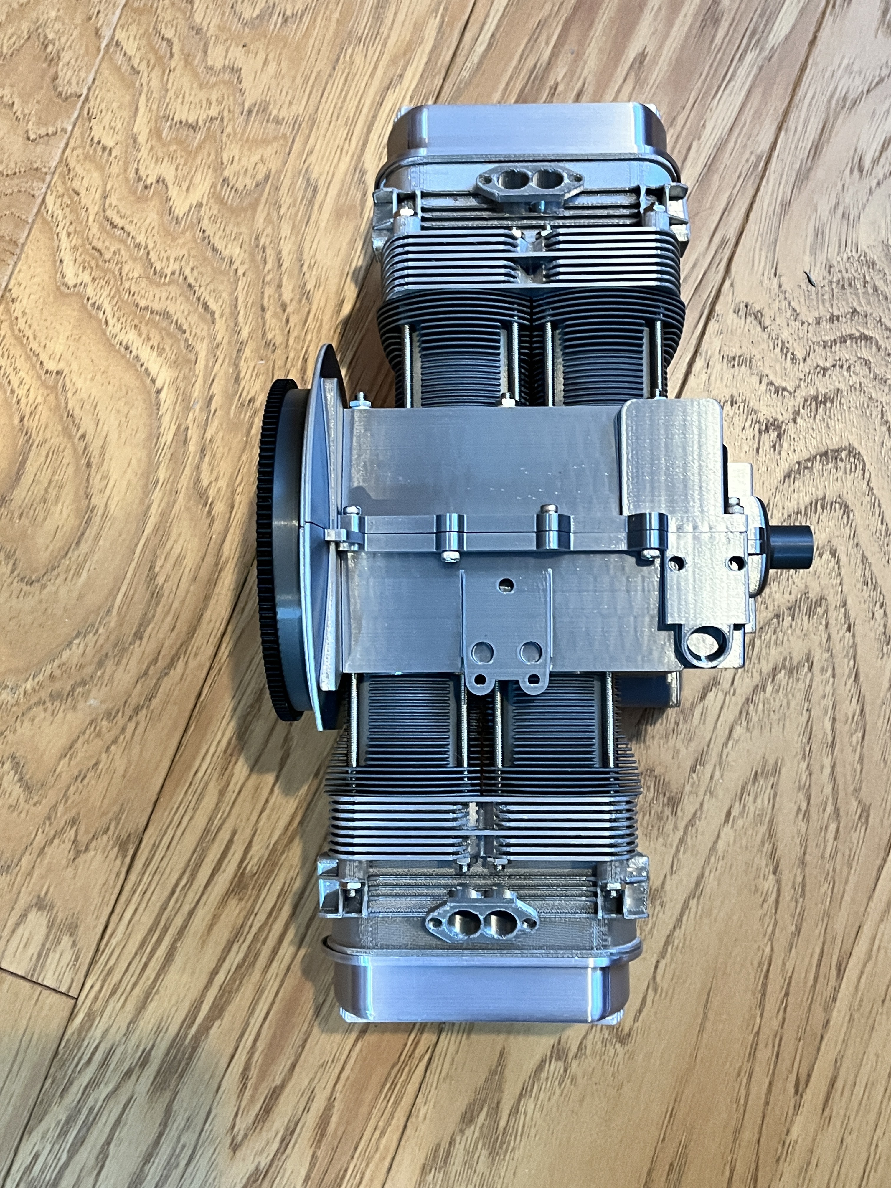
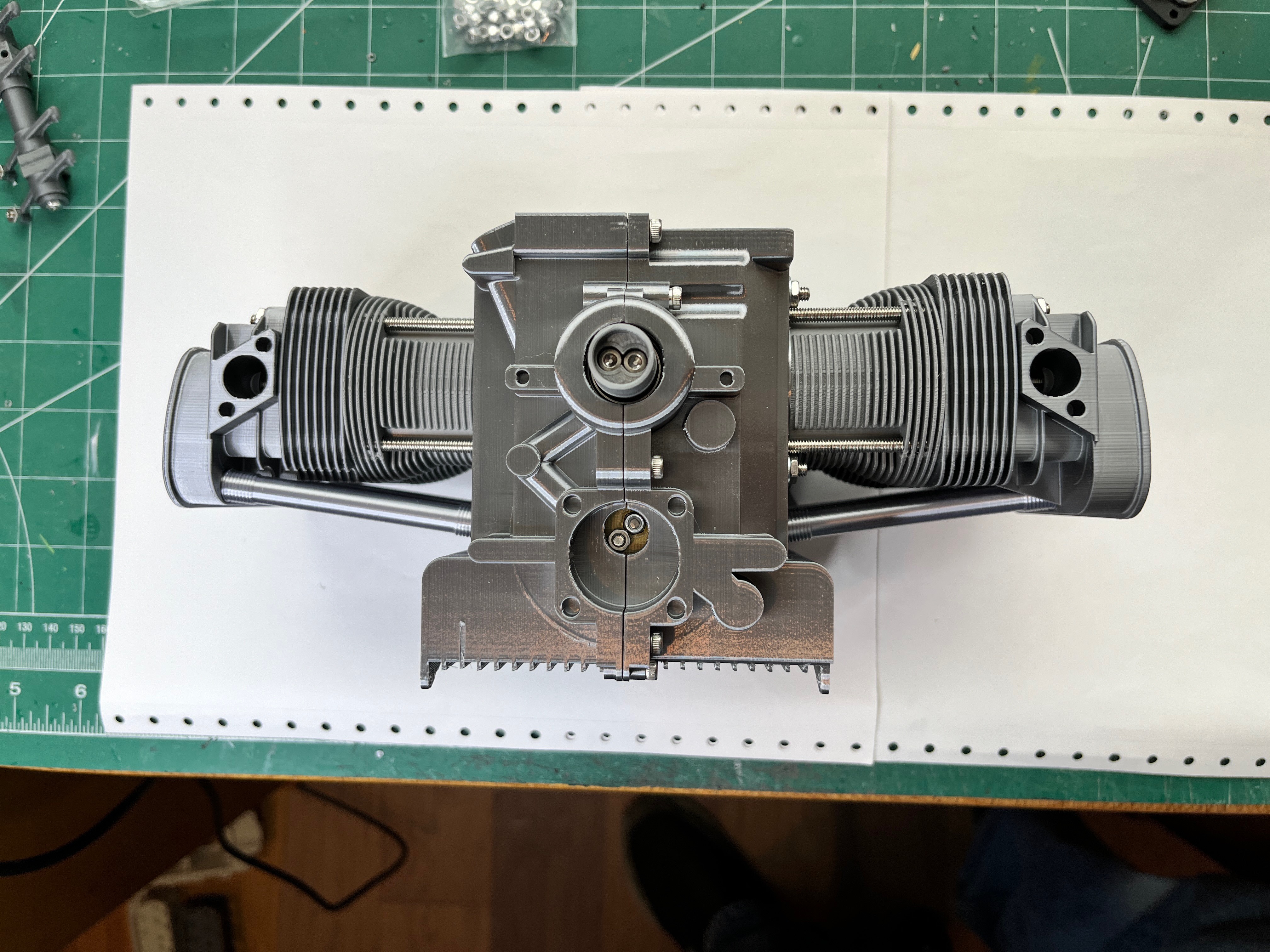
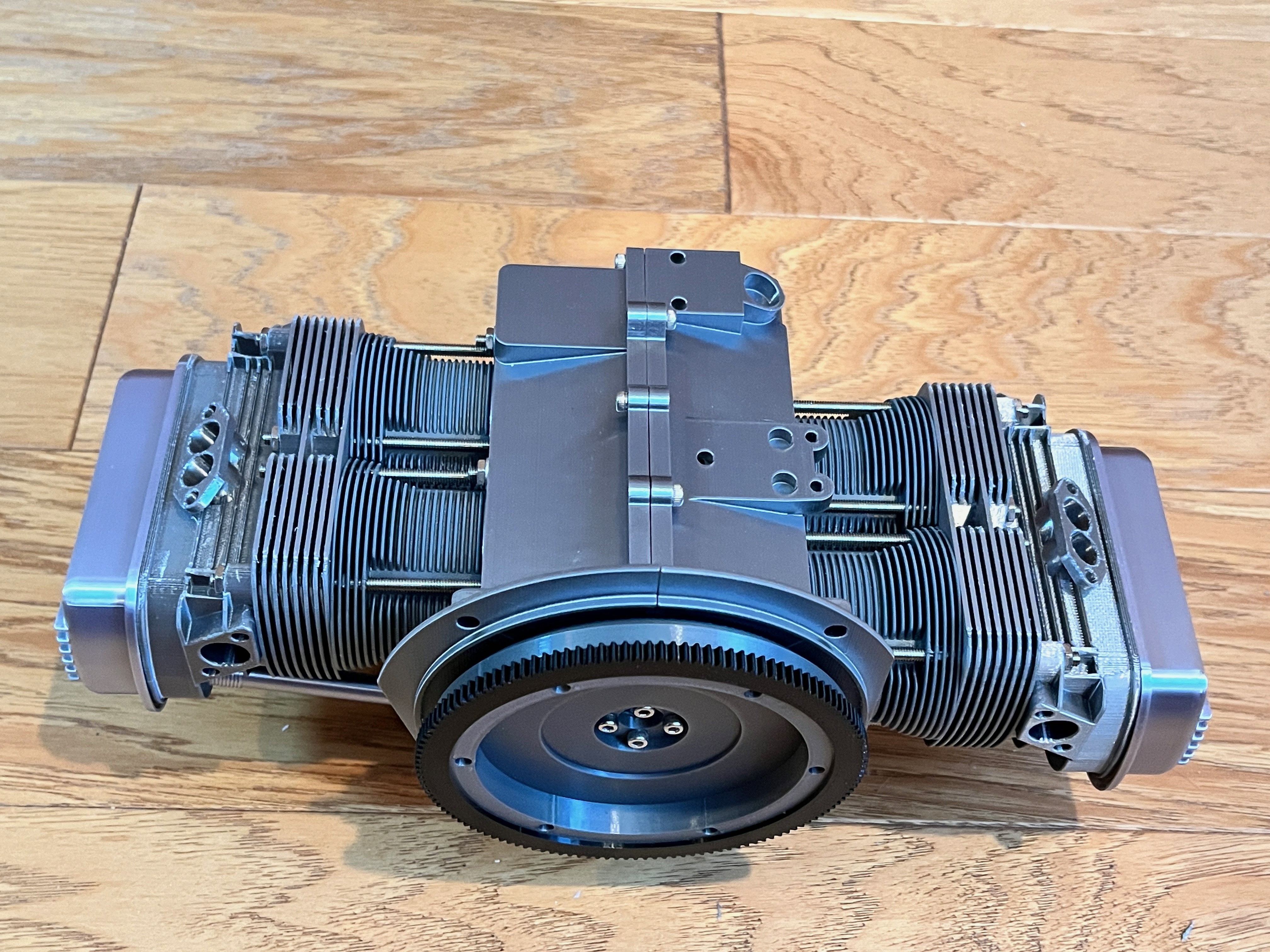
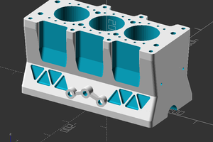
VW Engine and Transaxle

This is a 1/2.5 scale VW engine and transaxle with all internal parts.

Similar projects worth following
The goal is to build a working model of a VW type 1 engine and transaxle with internal parts. The engine will be driven by an electric motor embedded in the starter. The scale is 1/2.5 and the parts will be 3D printed except for things like valve springs, push rods and electric motor. The parts will be assembled using screws and metal inserts. The engine is a 1600cc displacement with aftermarket carburetors and exhaust.

This project is downloadable for free on Printables. There are 11 sub-model components that make up this entire model. If you go to my collections you can see all 11 sub-models as one collection.

The instructions, parts list and required hardware are all out on Printables.  There is an overview of each sub-model below in the logs.

  • Exhaust

    wglasford09/06/2025 at 21:07 0 comments

    And last buy not least is the header exhaust.  Here are the parts.

    The four pipes bolt to the heads.  The collector is then either fit in place or glued.

    The muffler tip is glued to the muffler and the muffler is bolted to the header collector.

  • Starter and Stand

    wglasford09/06/2025 at 21:04 0 comments

    What makes the whole thing go is the electric motor in the starting motor.  Here are the parts.

    This installs into the transaxle and the gear meshes with the flywheel which turns everything.

    You can see the wires, covered in sheathing, that plugs into the stand.  In the stand base is a motor speed controller and two connections, one that goes to the starter and one that accepts a 12v transformer input.

    The transaxle bolts to the stand and then the engine bolts to the transaxle.

  • Transaxle

    wglasford09/06/2025 at 21:00 0 comments

    The transaxle was the only part of this engine that I never cracked open so it was all new to me.  The drive shaft from the clutch goes over the axle driving part to the far end where the gears of the transmission portion are located and then power goes back towards the engine where the axle portion is located.  Here is the drive shaft going over the top of the axle portion.  You can see in most cases I used brass inserts to make assembly and disassembly easy. 

    The gears in the transmission portion are printed separately and stacked.  What I found out was the friction between these parts was too great to make them turn and actually shift so these parts are realistic but not functional in that they don't turn.

    There are two stacks of gears and a third reverse gear shaft.  Here you can see two of the shifter shafts.

    And the reverse shifter.

    These are the two gear stacks meshed together.

    In the other end is the throwout bearing.

    Inside the middle is the ring and piñon.  Here are the parts.

  • Carburetor

    wglasford09/06/2025 at 20:49 0 comments

    The carburetors are high end performance EMPI parts.  There are two carbs.  These have moving accelerator plates, accelerator pumps, floats and air filters.  Special springs are required to make the throttle assembly go back to idle, just like the real thing.  There are a lot of assembly pictures, this is just some of them.

  • Clutch

    wglasford09/06/2025 at 20:41 0 comments

    The clutch is fairly easy to install.  In the end I created a clutch tool to center the clutch plate when installing it.

    The friction plates are glued on.

  • Oil and Gas

    wglasford09/06/2025 at 20:38 0 comments

    This engine is very simple. This section consists of the fuel pump, the oil cooler, oil pump and even a dip stick.  Here are few pictures.  

  • Ignition

    wglasford09/06/2025 at 20:36 0 comments

    The ignition has removable spark plugs, spark plug wires that are made out of flexible silicon wire and internal distributor parts.  I decided not to have the distributor rotate.

  • Generator

    wglasford09/06/2025 at 20:33 0 comments

    The generator has rotating parts.  Notice that I used as realistic colors as possible.  Here are the parts.  The cooling fan bolts to the back side.  

    I used a rubber band as the generator belt.  Here is a completed picture.

  • Engine Tin

    wglasford09/06/2025 at 20:30 0 comments

    The engine is air cooled and surrounded by tin.  These parts are fairly thin.  The largest part, and the one that drove the scale is the fan housing which can be printed on a standard 210x210mm printer.  The underside of the tin is an aftermarket type that allows for an aftermarket header exhaust.  Here are the parts.

    And some completed pictures.

  • Engine Block

    wglasford09/06/2025 at 20:24 0 comments

    The crankshaft and camshaft consist of many parts that are bolted together with bearings throughout.  This is the crankshaft and its parts.

    And the camshaft and its parts.  This engine is interesting in that the boxer design allows it to share camshaft lobes between opposing cylinders.  In other words, there are 8 valves that need lifting and only four lobes on the camshaft.

    Here is the case half with the through studs that hold the case halves together around the crankshaft.

    The cylinder sleeves go onto outer studs just like the real thing.

    The valves have valve springs to they move as the engine rotates.

    The rocker arm has adjustable backlash bolts just like the real thing.

    Here are some completed engine block pictures.

View all 10 project logs

Enjoy this project?

Share

Discussions

Similar Projects

Does this project spark your interest?

Become a member to follow this project and never miss any updates