Arnov Sharma
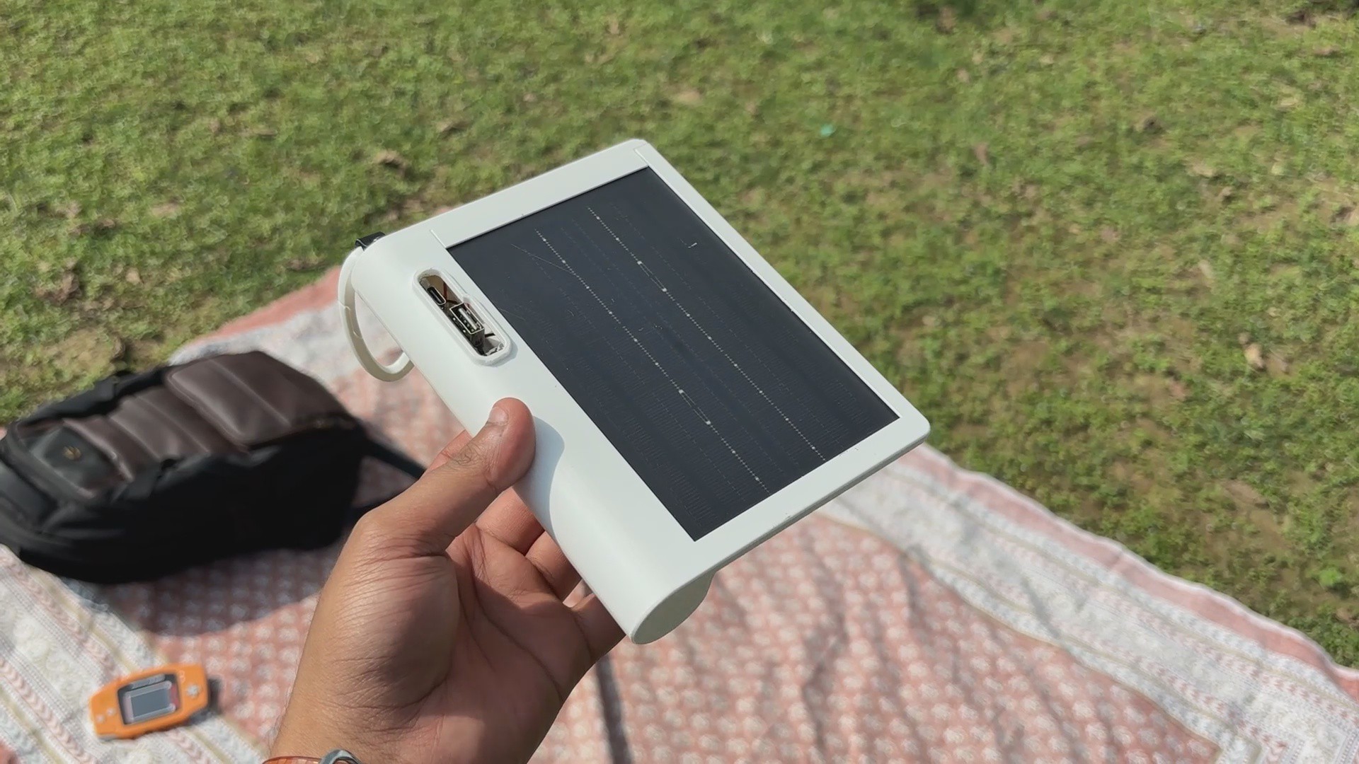


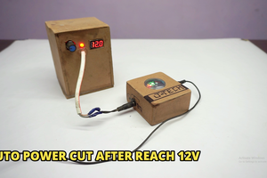
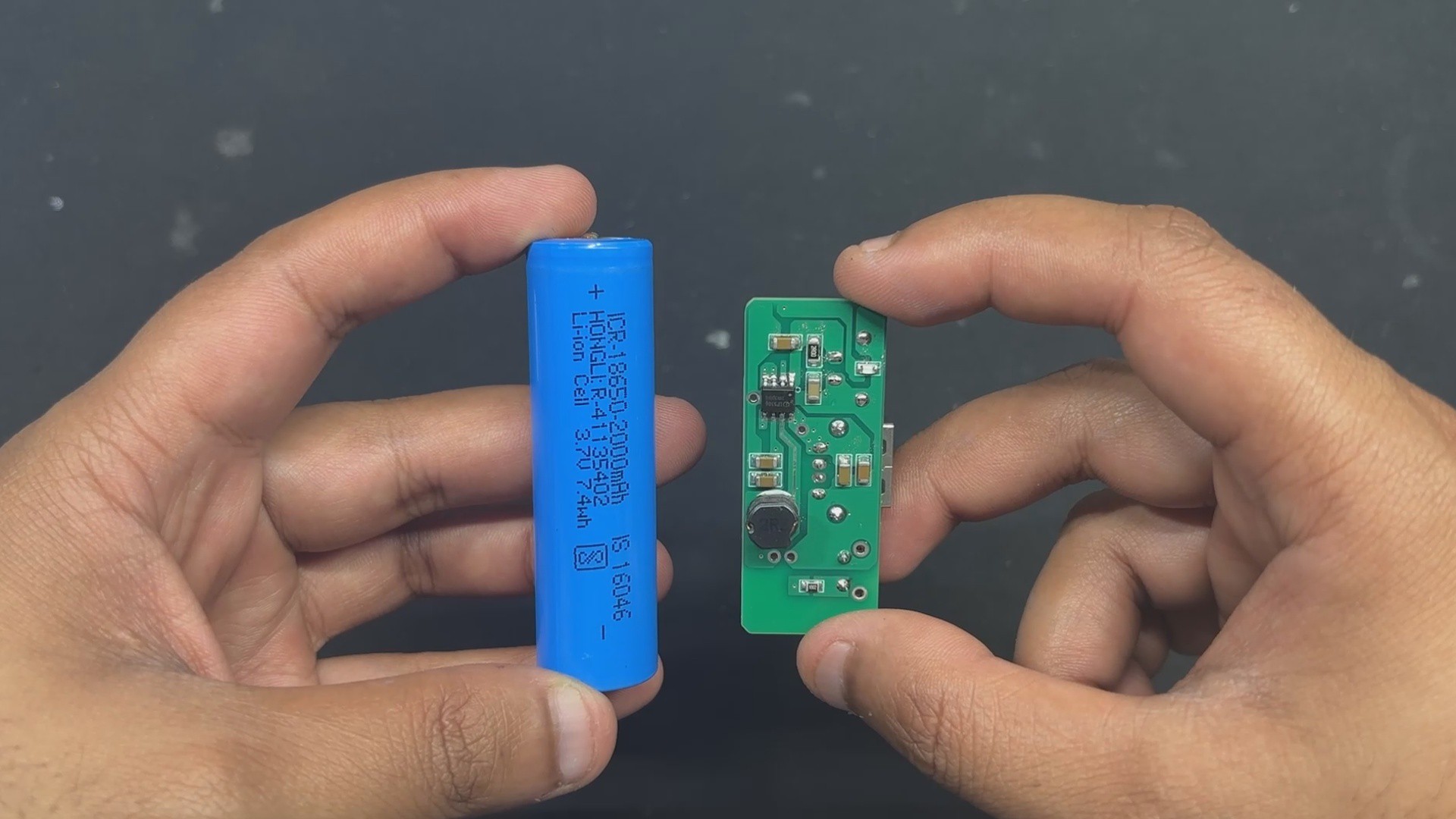
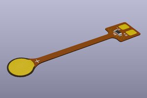
The 2W high-efficiency PTFE panel we're using can supply 5V 400mA, which is more than enough to charge our 2000mAh Li-ion battery.
Solmate's ultra-slim body and a custom carabiner hook make it the perfect companion for outdoor enthusiasts, travelers, and backpackers—simply clip it to your bag and let it charge while you explore. Whether you're hiking through the hills or commuting through the city, SolMate keeps your devices energized using nothing but sunlight.
DESIGN PROCESS


SolMate’s body was designed in Fusion 360, drawing inspiration from the Lenovo Yoga Tablet’s distinctive form. Just like the Yoga’s cylindrical edge that allows users to prop the tablet at an angle, SolMate features a similar contour—not just for aesthetics, but to enhance usability and portability.
This thoughtful shape makes it easy to grip, clip, and carry, while maintaining a slim profile that blends seamlessly with your gear. Not even aesthetics; a solar panel needs to be placed at an angle facing towards sunlight. This shape makes sure it is always placed at an angle, which will allow the user to get the max potential of the solar panel!
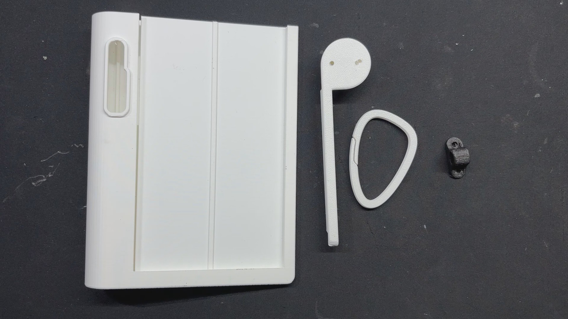
SolMate is built from two main parts: the main body, which holds the solar panel, battery, and circuit, and the lid, which pressure-fits from the top to seal everything in place.
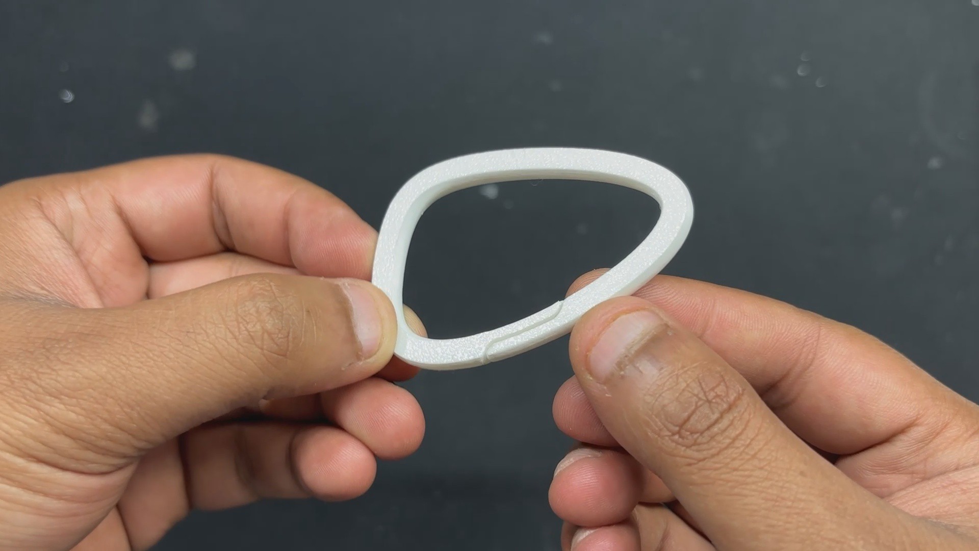
One small but useful design touch was adding a custom carabiner clip. Originally made for climbing gear, carabiners are spring-loaded loops that make it easy to attach things securely. These days, they’re everywhere—used to clip water bottles, keys, or gadgets to backpacks.
For SolMate, it means you can just hook it on and let it charge while you move. Simple, secure, and built for the outdoors.
Unlike traditional metal carabiners with spring-loaded gates, our custom carabiner is made from regular PLA and operates on a simple yet effective principle: material bend. The clip is designed with a narrow opening and a slightly curved shape that allows the plastic to flex when pressure is applied.
PCB DESIGN
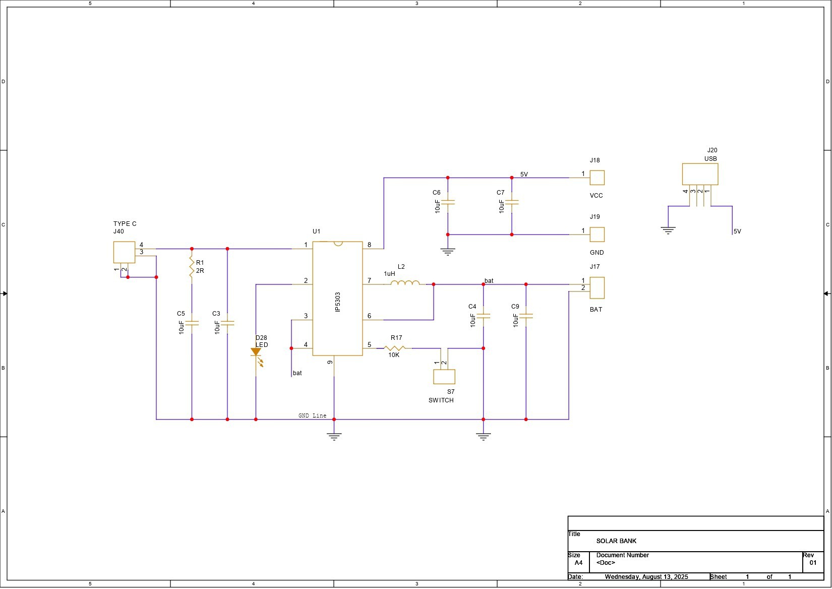


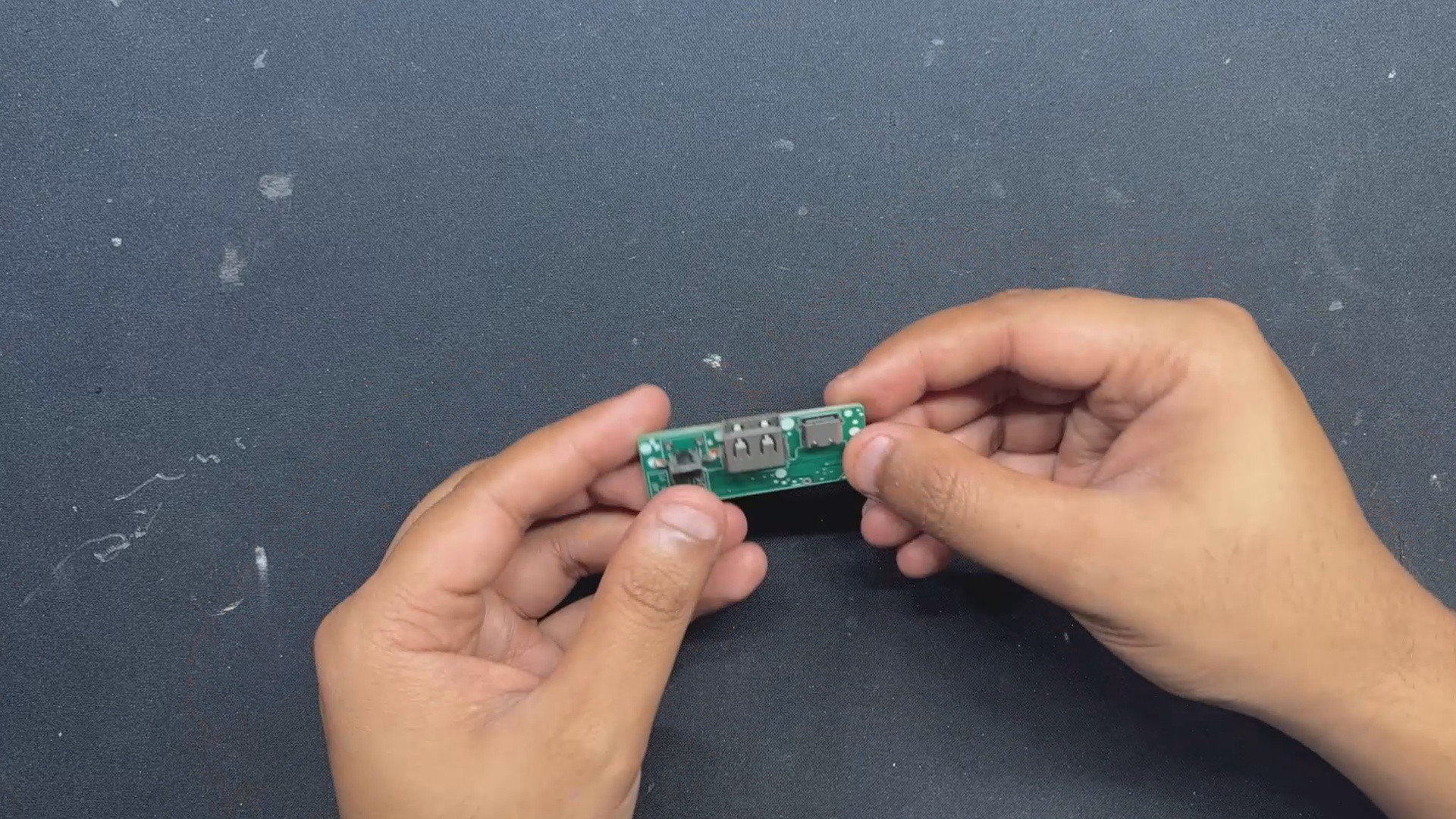
Here we are using the IP5306 Power Management IC Setup, which we have previously used in many of our battery-related projects. This SOIC8 package IC can provide a stable 5V 2.4A from a 3.7V lithium-ion or LIPO cell and also includes many important functions such as overcharging protection, overdischarge, battery fuel level, and charging status.
Below is its datasheet if you want more info on this IC.
https://www.skytech.ir/DownLoad/File/2566_IP5306.pdf
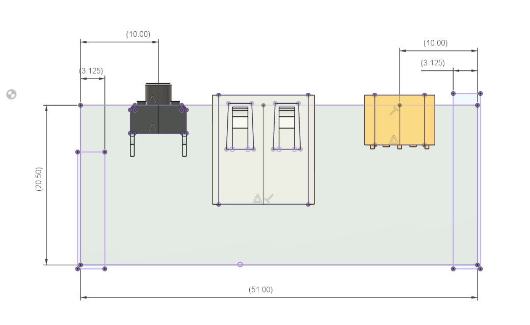
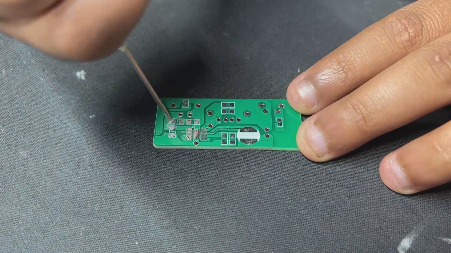
We created the board outline in PCB CAD by following the customized circuit design from our Fusion 360 CAD file. We finalized the board layout by placing all the components in order with the CAD's measurements. Once everything lined up, we prepared the final board for fabrication.
NextPCB PCB Service
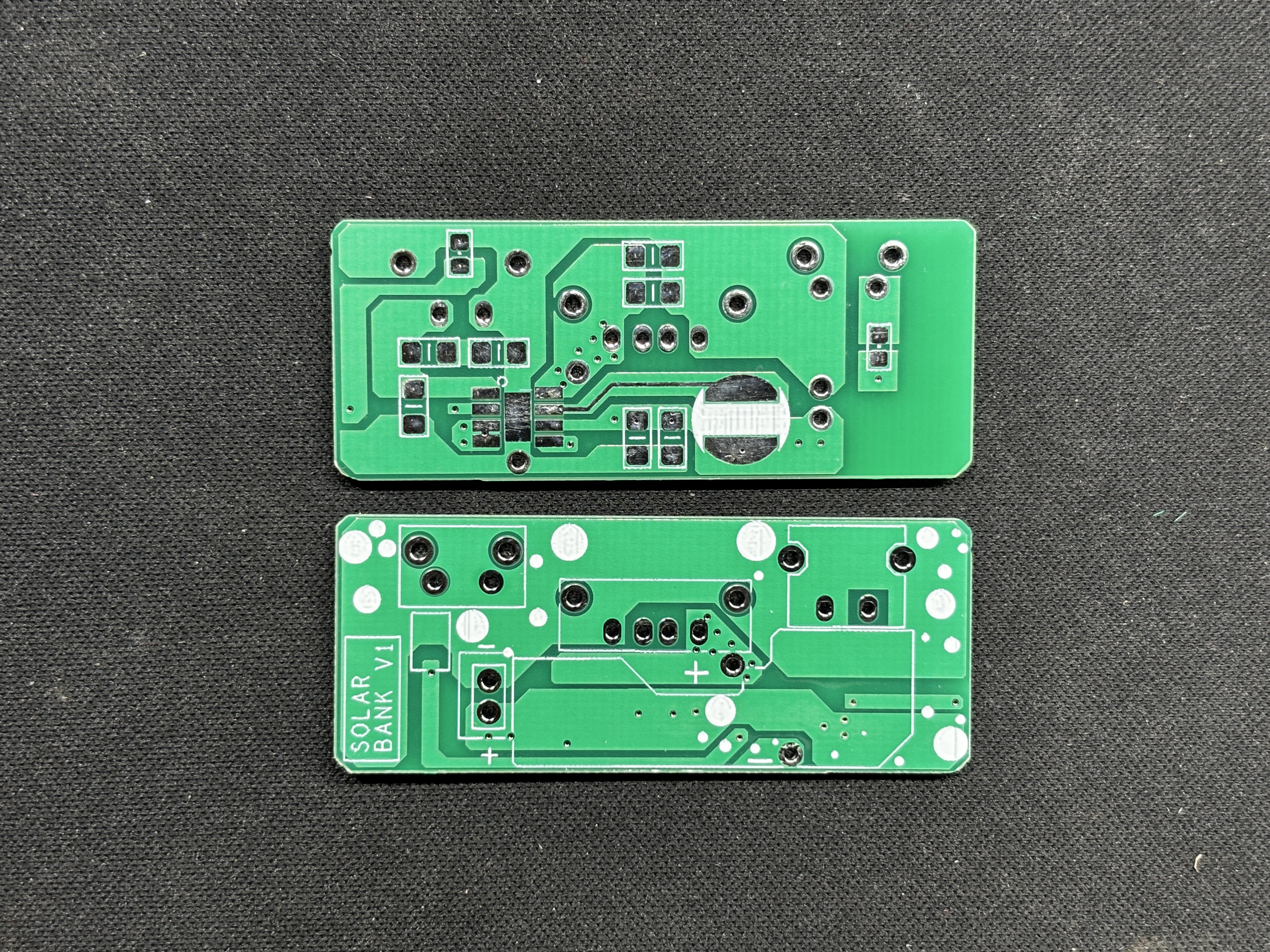
After completing the PCB design, Gerber data was sent to HQ NextPCB, and an order was placed for a white solder mask with black silkscreen.
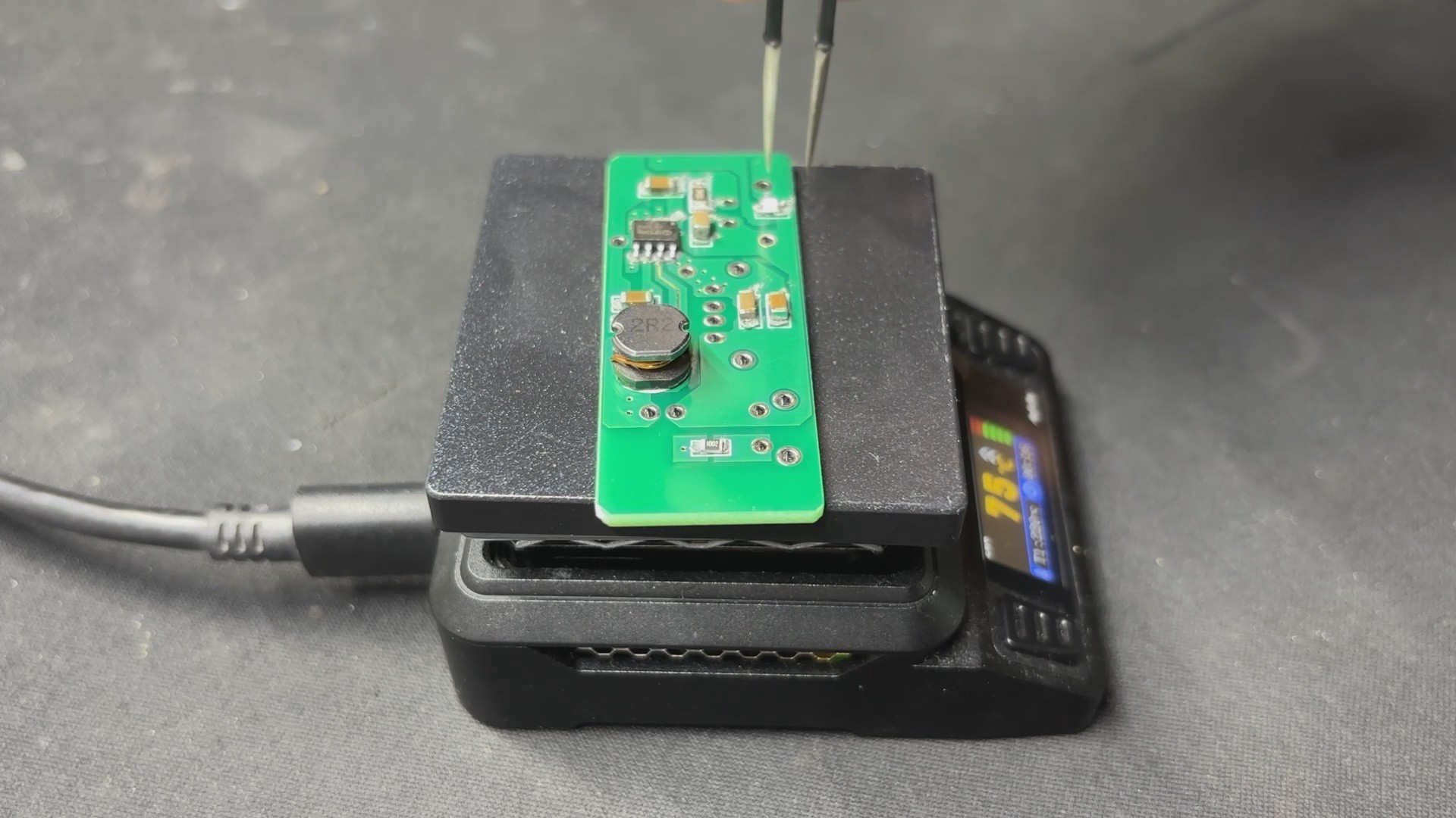
After placing the order, the PCBs were received within a week, and the PCB quality was pretty great.
In addition, I have to bring in HQDFM to you, which helped me a lot through many projects. Huaqiu’s in-house engineers developed the free Design for Manufacturing software, HQDFM, revolutionizing how PCB designers visualize and verify their designs.
Take advantage of NextPCB's Accelerator campaign and get 2 free assembled RP2040-based PCBs for your innovative projects.
https://www.nextpcb.com/blog/rp2040-free-pcba-prototypes-nextpcb-accelerator
This offer covers all costs, including logistics, making it easier and more affordable to bring your ideas to life. SMT services can be expensive, but NextPCB is here to help you overcome that hurdle. Simply share your relevant project, and they'll take care of the rest. Don't miss out on this amazing opportunity to advance your tech creations!
HQDFM: Free Online Gerber Viewer and DFM Analysis Tool

Also, NextPCB has its own Gerber Viewer and DFM analysis software.
Your designs are improved by their HQDFM...
Read more »


 Jose Ignacio Romero
 Mahesh Venkitachalam