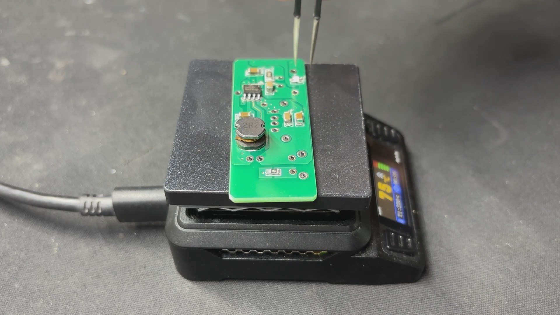
PCB assembly starts by applying solder paste to each SMD pad using a dispensing syringe. We’re using standard 63/37 Sn-Pb solder paste. Once that’s done, each SMD component is placed in position using ESD-safe tweezers.
The board then goes onto a mini reflow hotplate, which heats it from below. As soon as the temperature hits around 200°C, the solder paste melts and the components are soldered in place.
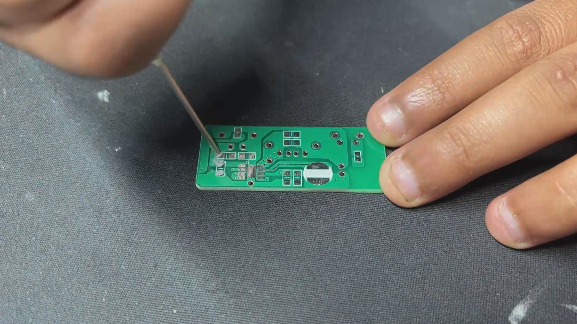
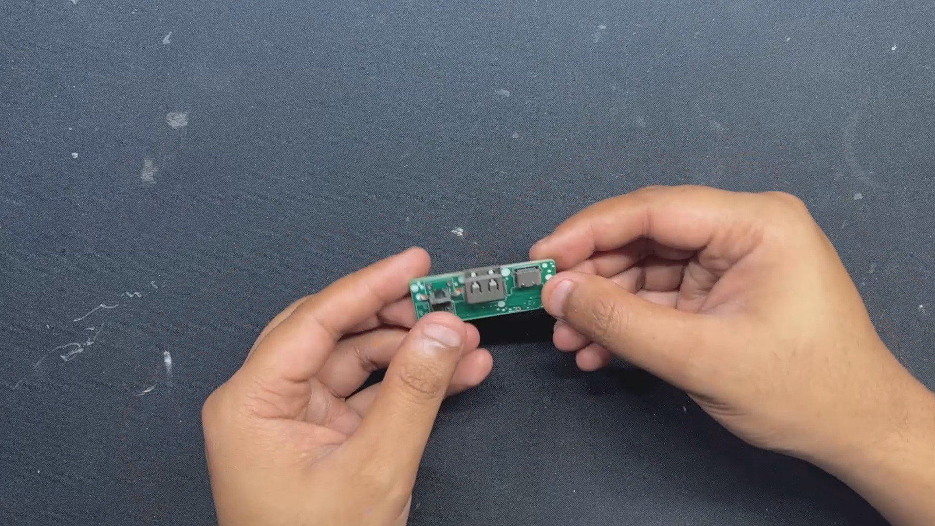
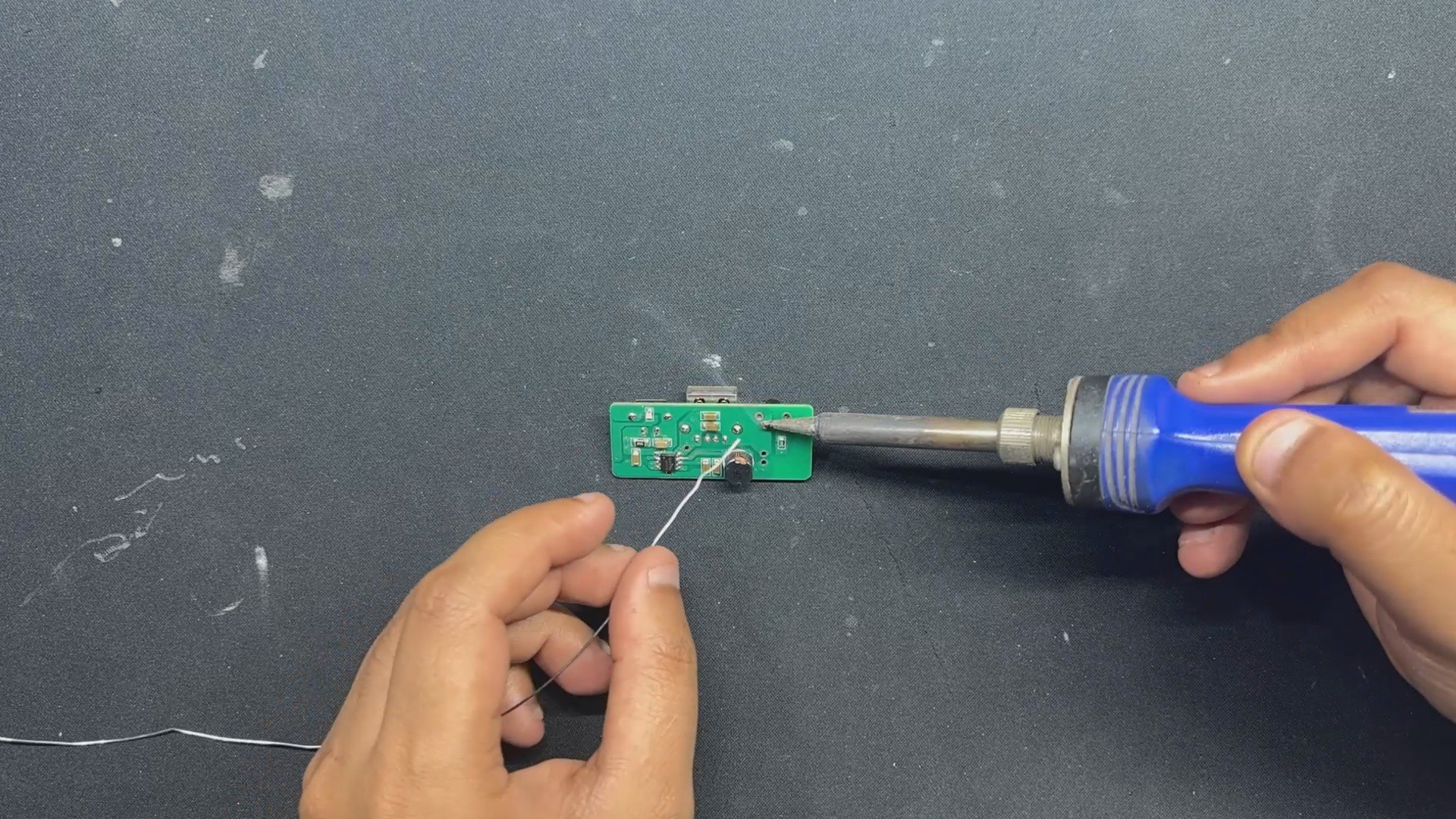
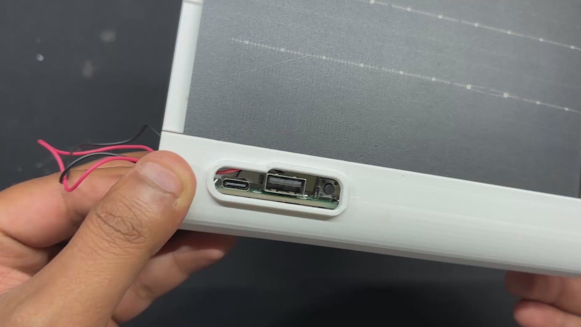
Next, we move on to the through-hole components—starting with the USB port, then the push button, and finally the Type-C port. After placing them, we flip the PCB and solder the through-hole pads using a soldering iron. That wraps up the full assembly process.
2
POWER SOURCE
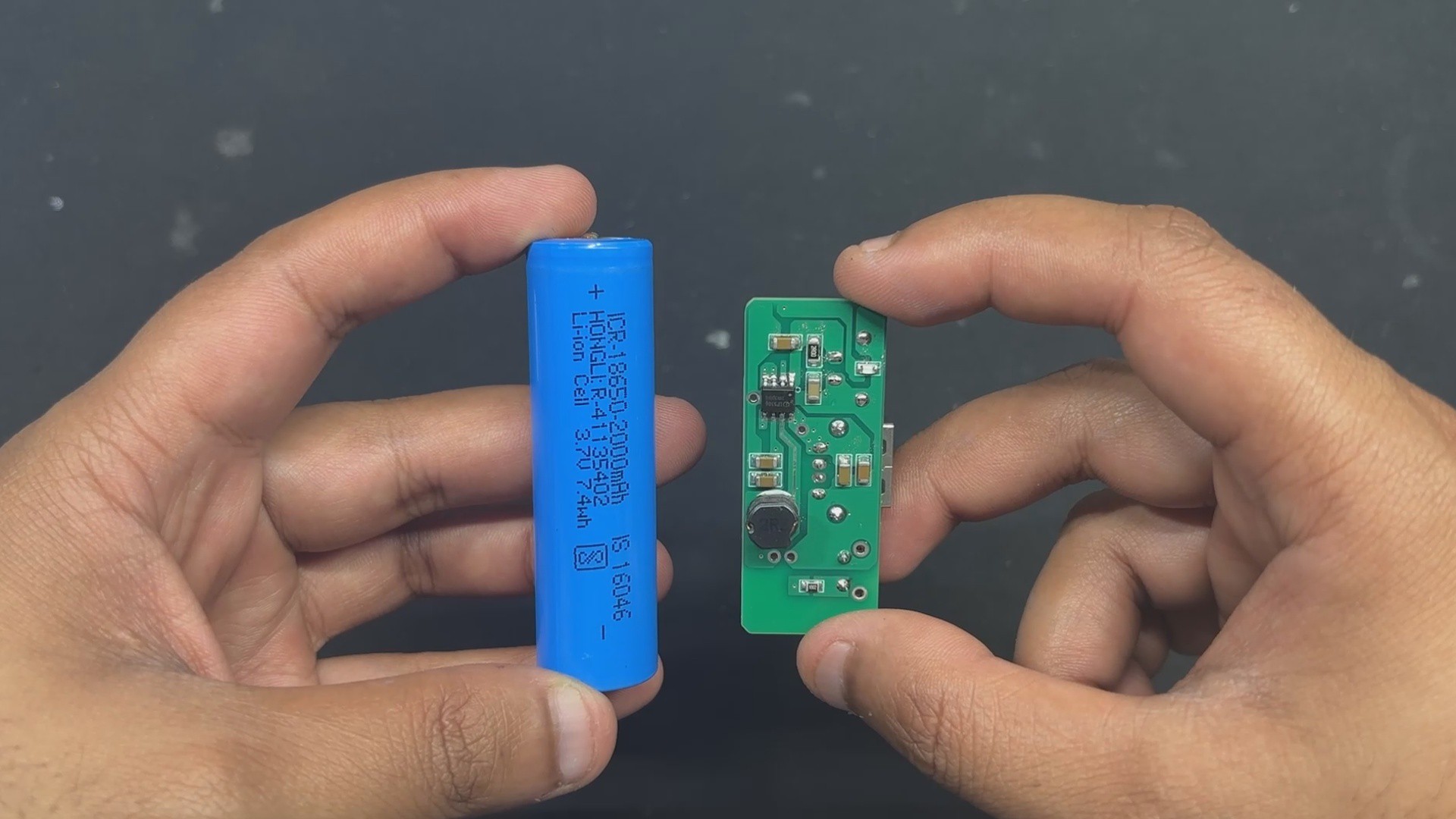
For power, we’re using a 3.7V 2000mAh Li-ion cell, which works well for this setup. Since the panel is rated at 2W, going with a larger battery would just slow down charging.
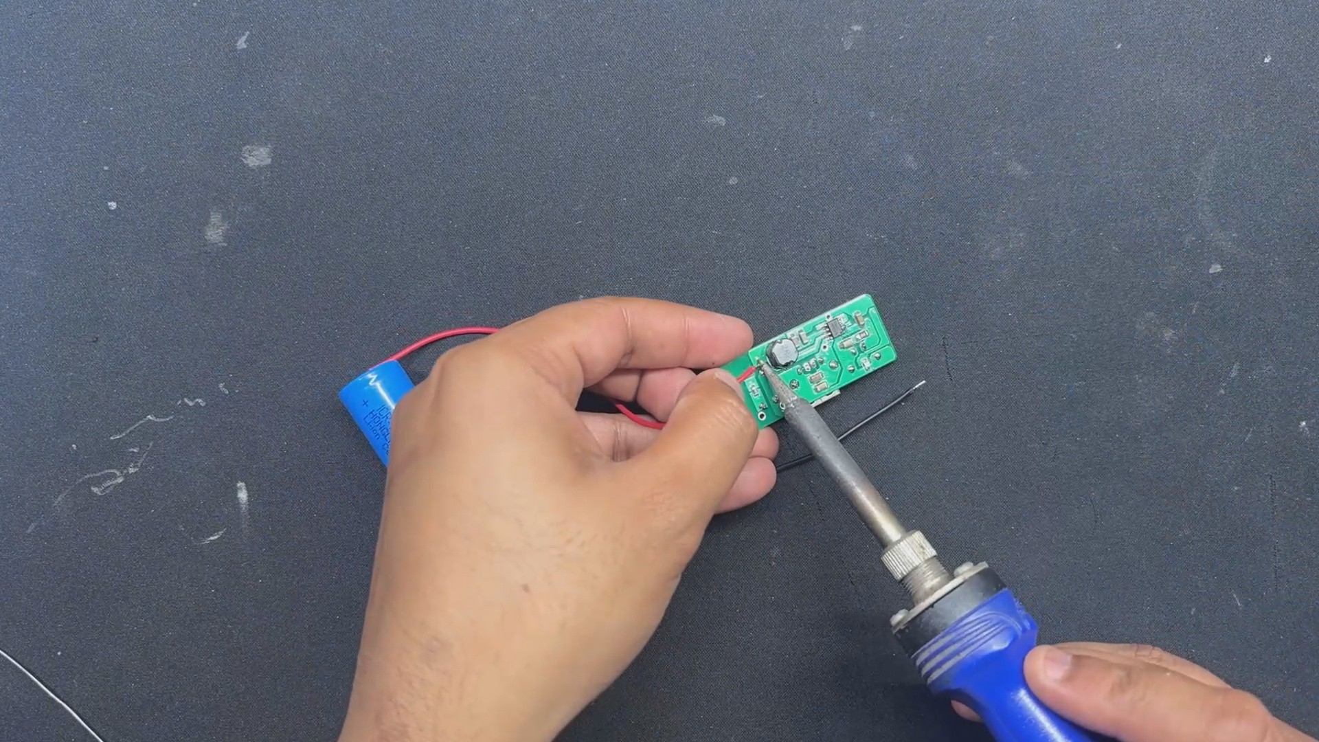
We connect the battery’s positive lead to the positive terminal on the circuit and the negative to the negative terminal.
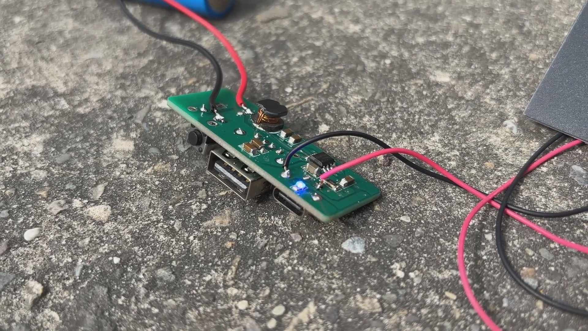
Pressing the push button powers up the circuit, and the indicator LED confirms it’s working.
To be sure everything’s running properly, we plug in a USB power meter and get a stable 5V output, which means the setup is good to go.
3
2W PTFE SOLAR PANEL
The 2W PTFE solar panel is the project's main highlight. Polytetrafluoroethylene, or PTFE, is the same substance used to make Teflon and other non-stick cookware, so this isn't your typical solar panel.
In place of conventional glass, PTFE is used in solar panels as a flexible, lightweight, and weather-resistant layer. This means that the panels we use are lighter, thinner, and have a non-breakable layer, which is significantly better compared to traditional glass.
It's lighter but has a drawback, which is efficency, its effiecny is slightly lower than traditional glass panels because of the fact that the PTFE layer tends to scatter incoming sunlight more, which means less direct light hits the solar cells underneath. That scattered light either gets reflected away or diffused inefficiently, leading to lower energy conversion compared to glass-covered panels that use anti-reflective coatings and high-transmission surfaces.
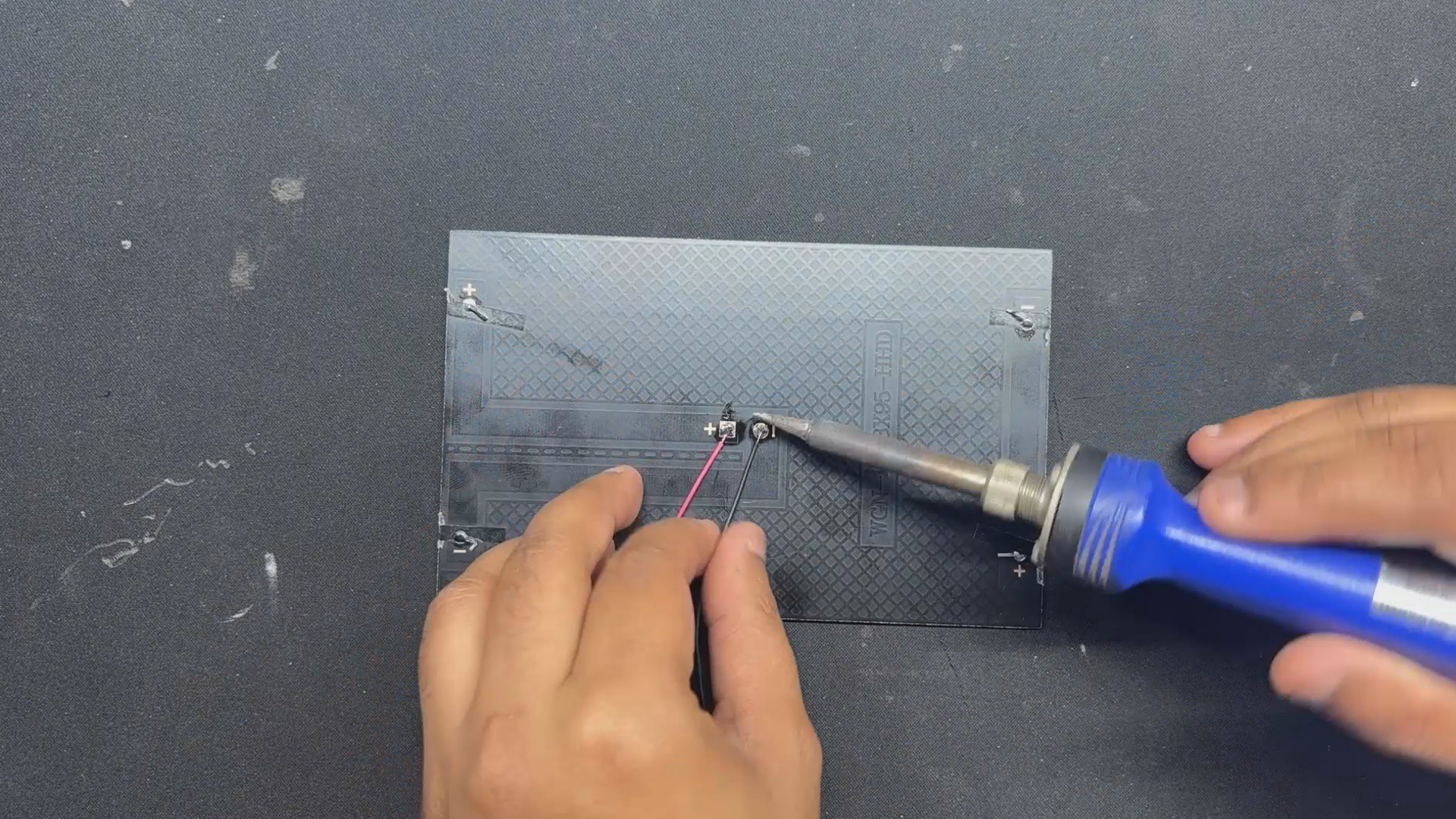
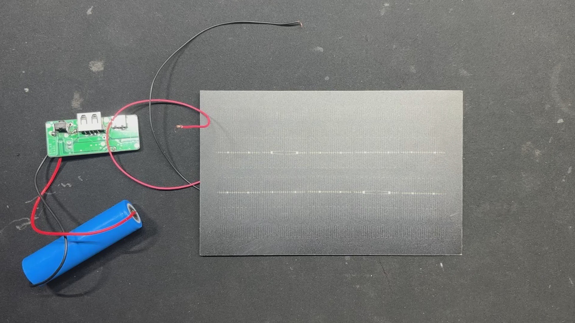
For our testing, we connected two wires to the Positive and negative terminals of the panel, then used a multimeter to measure the voltage which was around 3.9V. It's lower because we are in a room; this panel voltage can reach to 6V at no voltage but its nominal voltage is around 5V making it ideal for charging the Lithium Cell via Power management circuit.
4
INITIAL TESTING
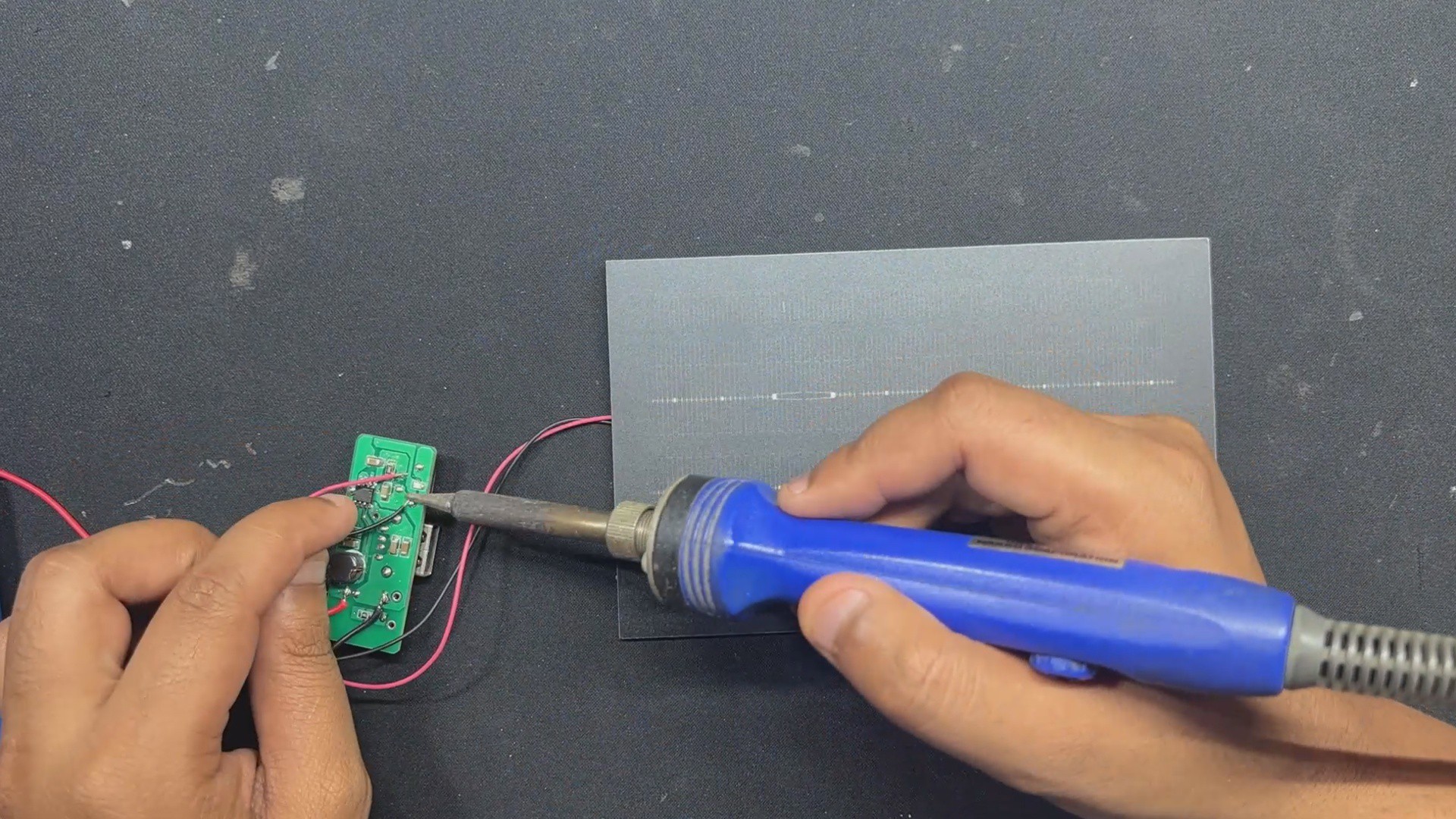
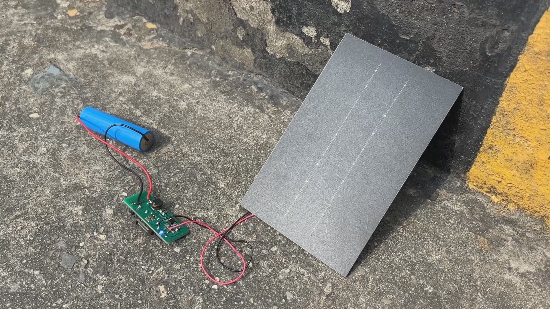
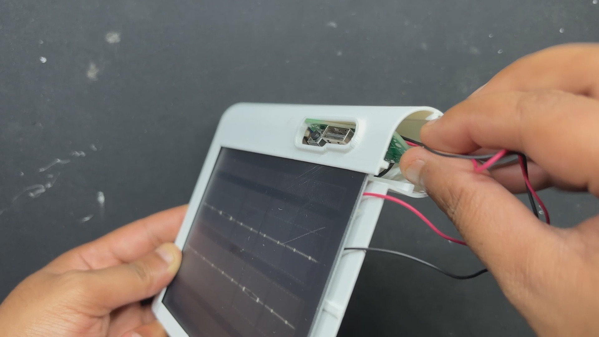
Before assembling the entire setup, we first connect the VCC and GND terminals of the solar panel to the circuit's Charging IN connector. This enables us to supply 5V from the solar panel to the charging terminals of the IP5306.
We put the device outdoors in the sun to see if it charged using solar power. When we did, we noticed that the indicator LED was blinking, indicating that the device was charging.
In the peak sunlight, it took about four hours for the battery to fully charge. The current was 200 mA overall, with a 400 mA peak. As the cell approaches 4.2 V, the current decreases gradually.
We can now proceed to the project's last stage after ensuring that all of the electronics are operating flawlessly!
5
BODY ASSEMBLY
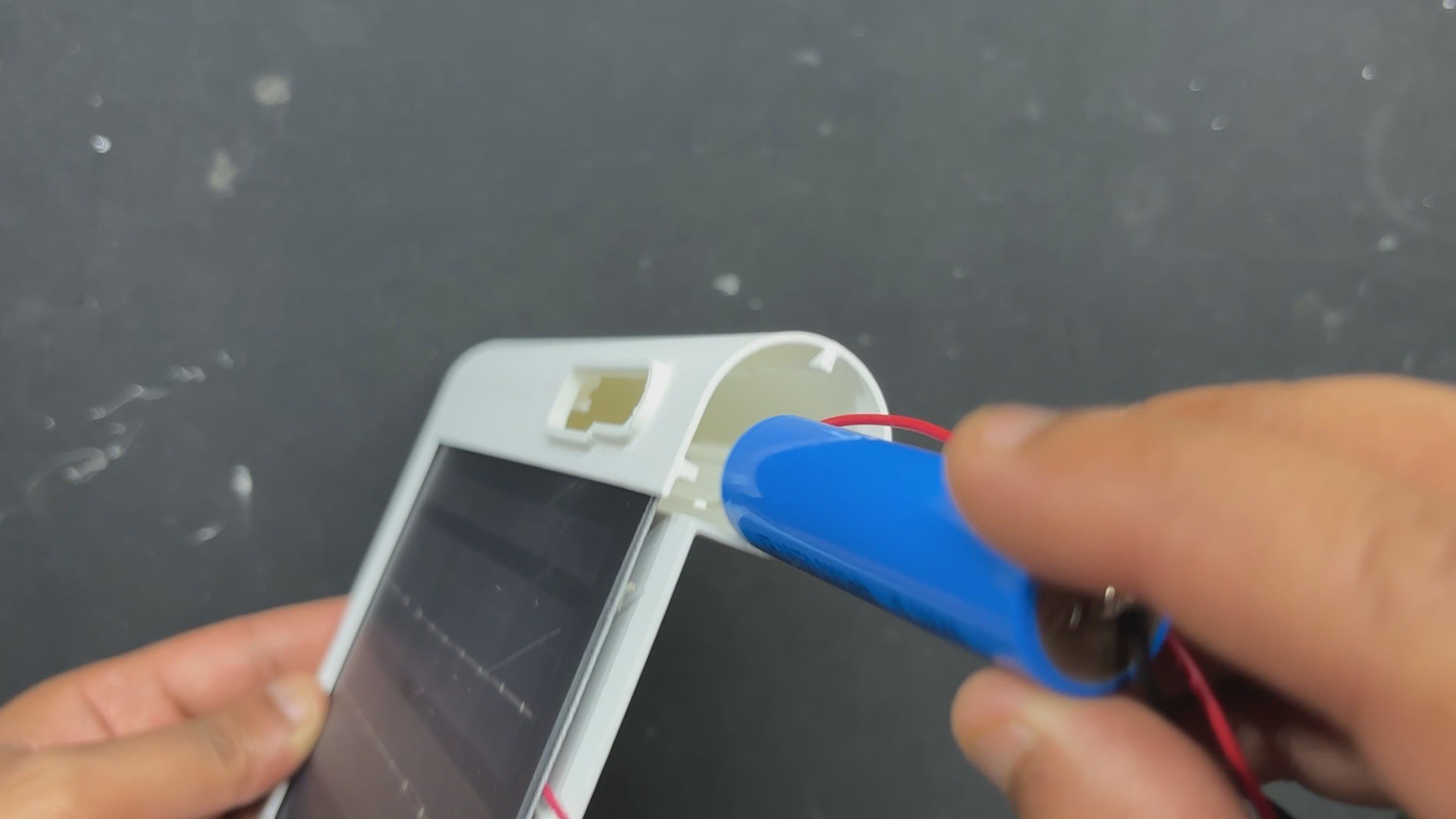
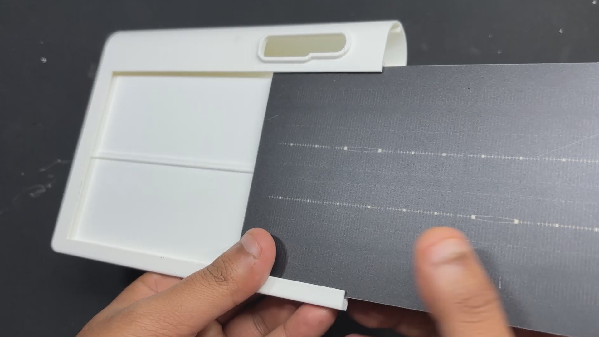
The PTFE solar panel is slid into position inside the main body.
Next, the circuit and lithium cell slide into place, and we tuck all of the wires inside the device.
After that, the lid is secured in place. The inner and outer surfaces of the lid are pressure fitted together because there is no space between them. We use super glue over the lid's perimeter to ensure that both pieces are securely joined, permanently joining them.
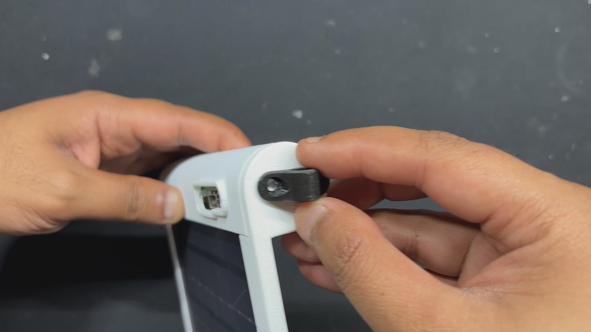
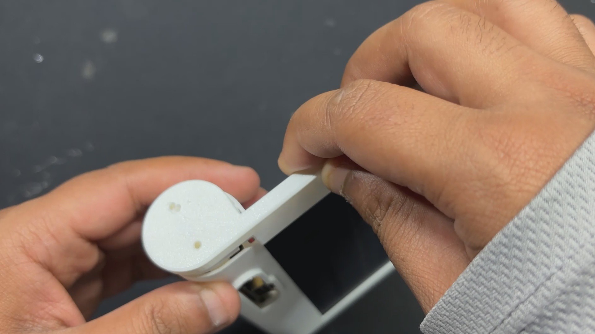
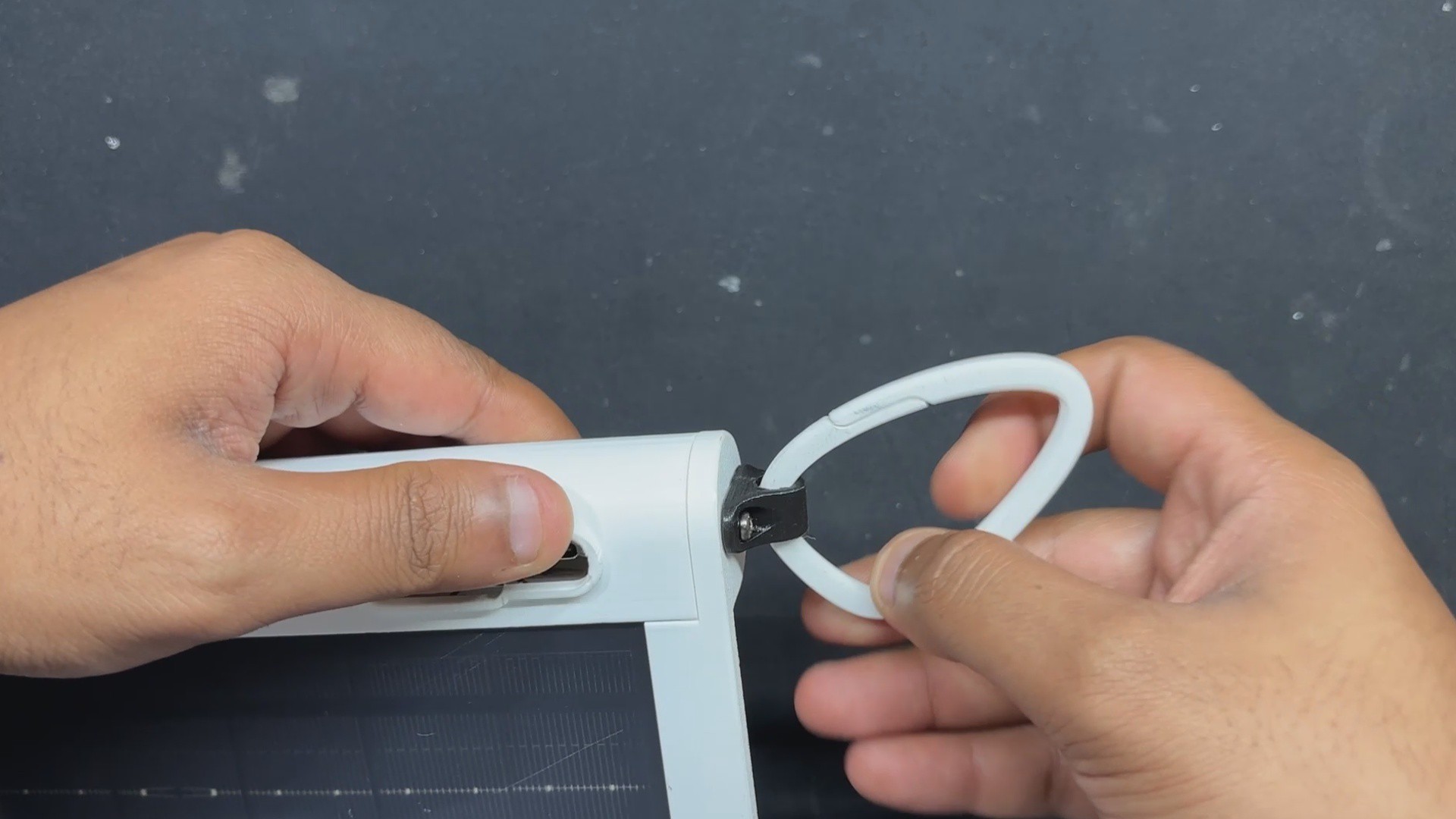
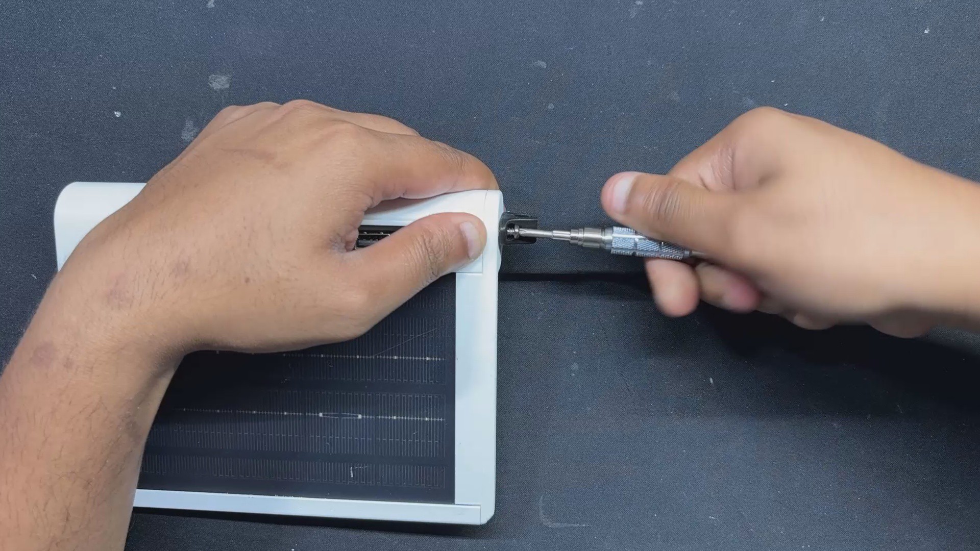
The carabiner will be held in place by a holder part that we attach over the lid next. This holder part is secured with lid using two M2.5 screws.
The assembly process is then completed by adding a carabiner to the Holder part.
6
RESULT
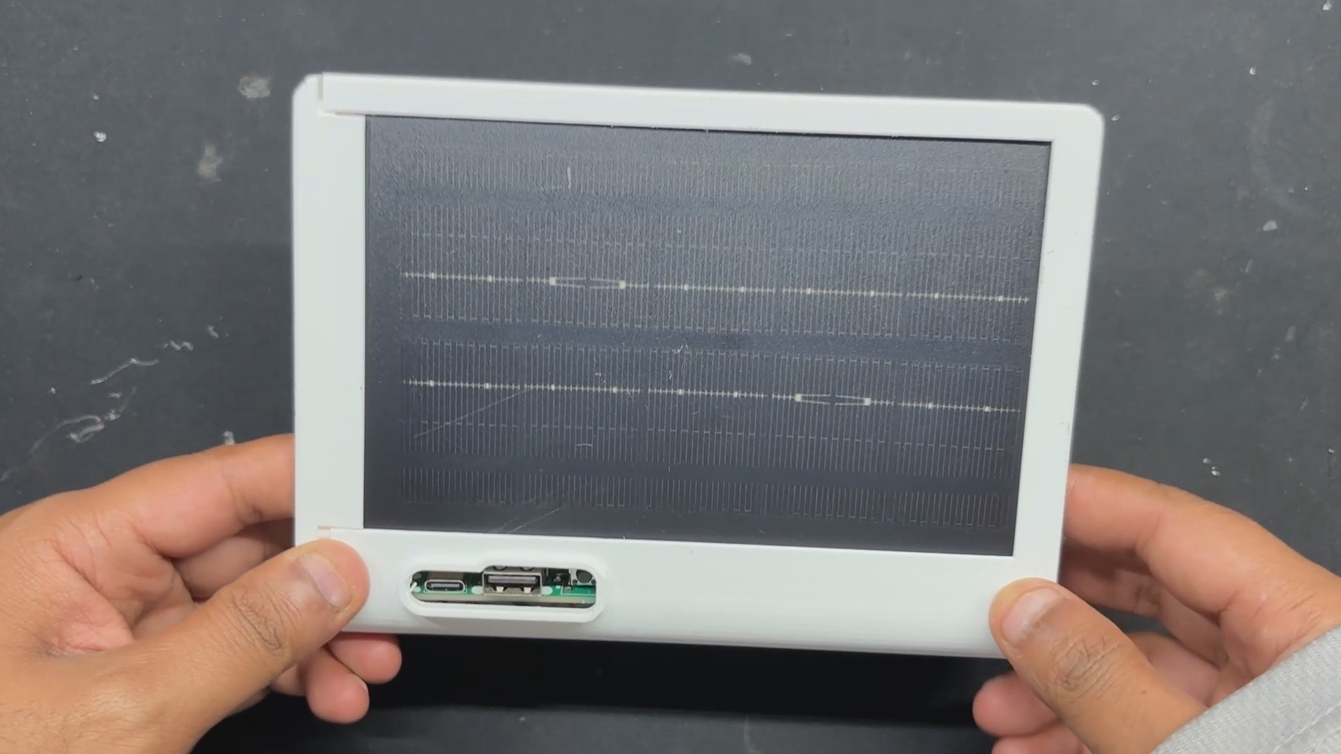
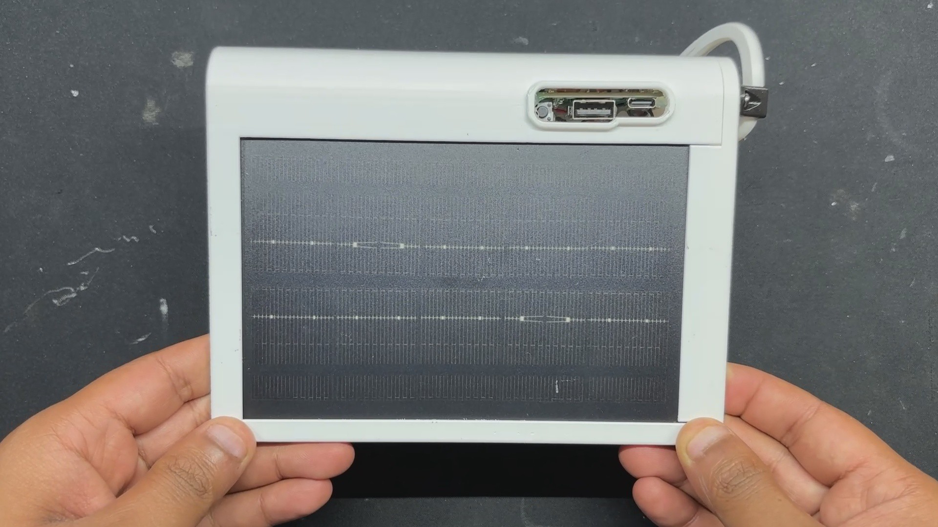
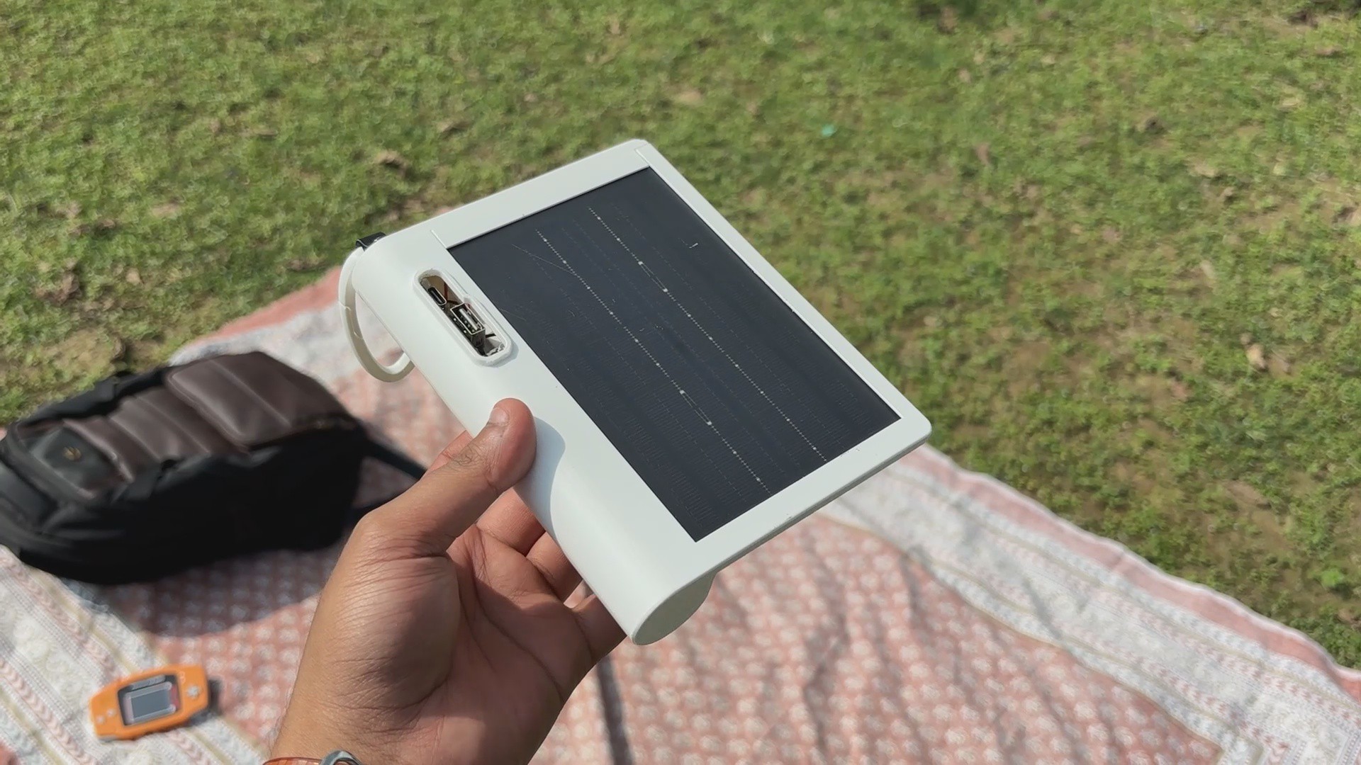
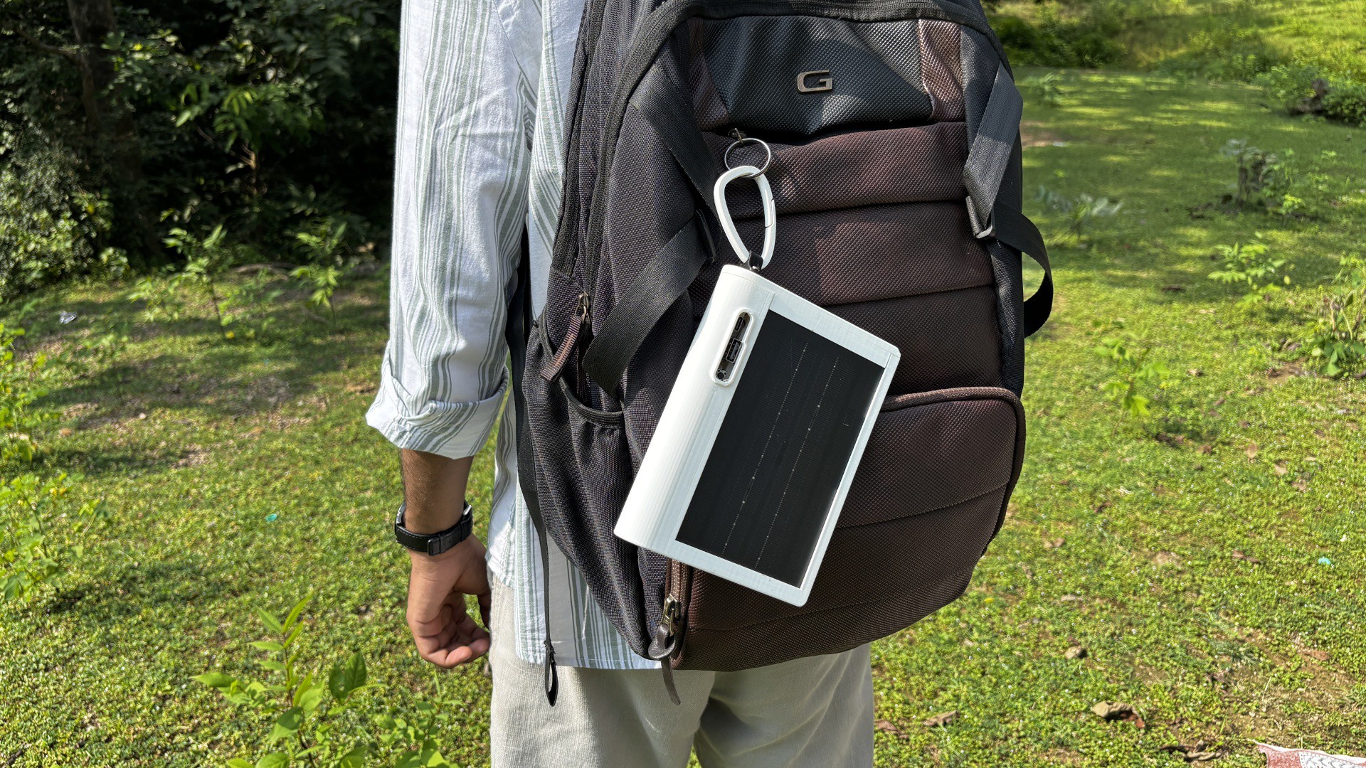
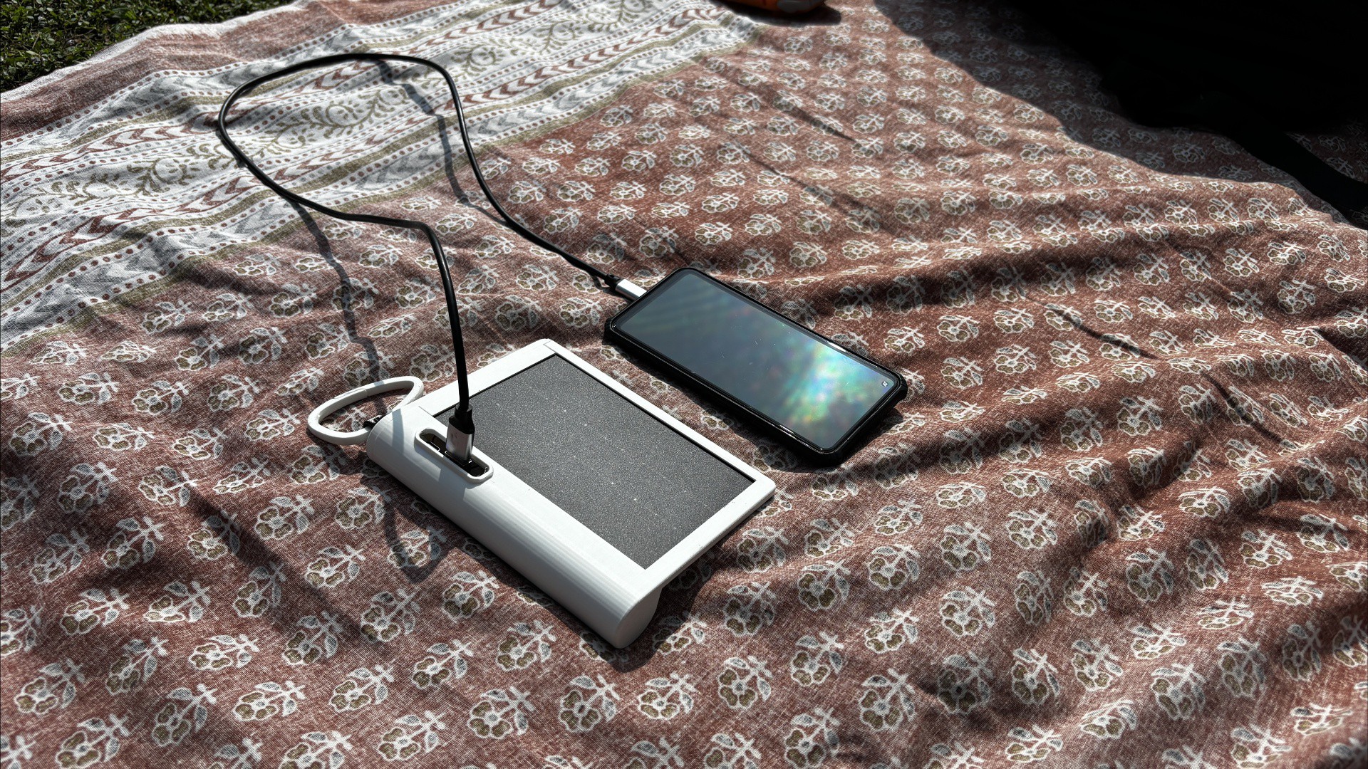
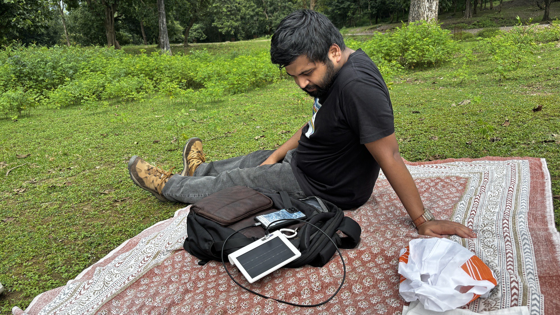
Here's the final result of this simple yet helpful build: SolMate, a portable solar power bank designed for life on the move. Just clip it on your bag and let it charge any of your devices on the move!
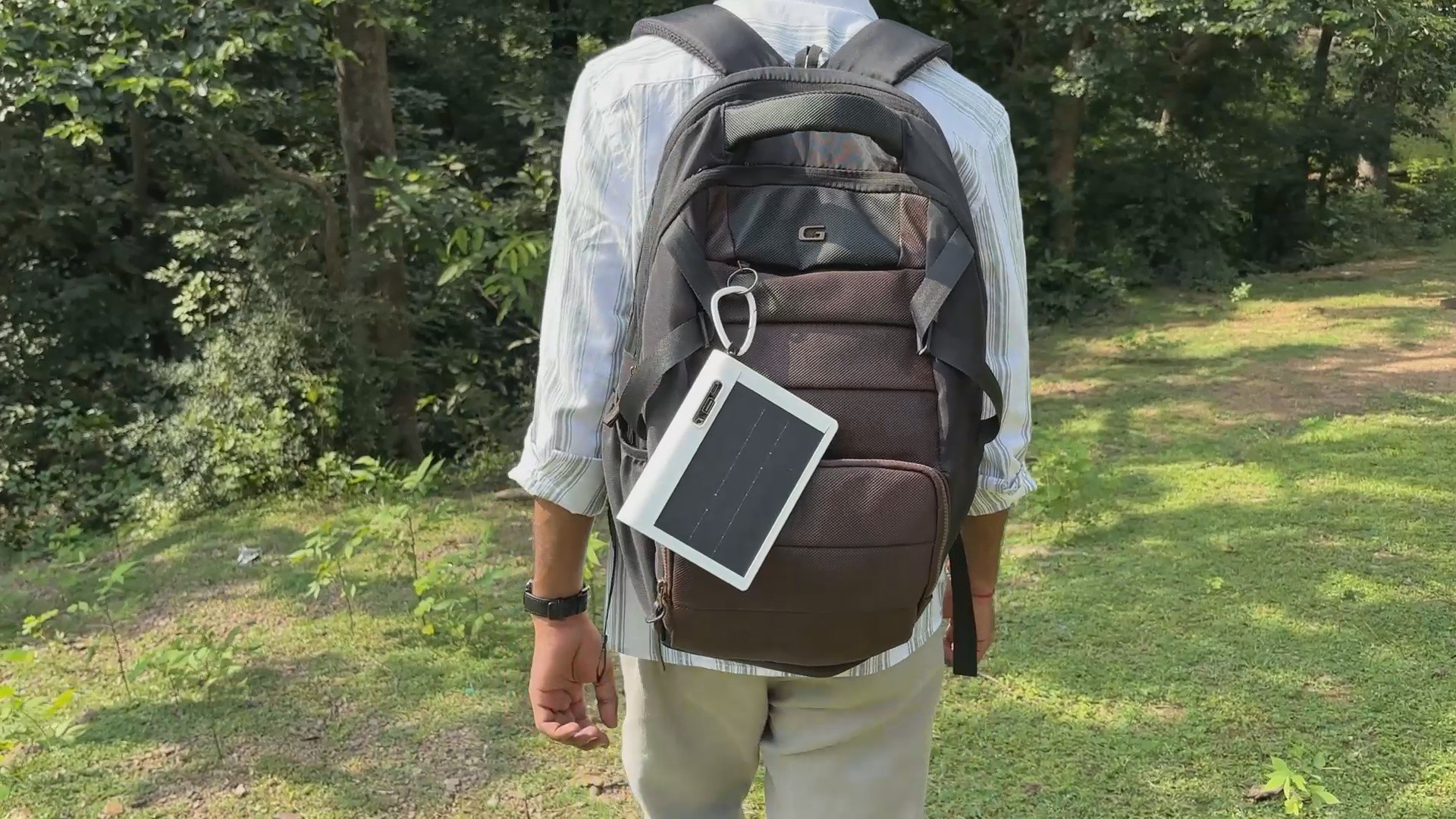
We took SolMate out for a real-world test on a short trek to a nearby mountain. Once we reached a good spot, we settled down and plugged in our phone—it was at 55%. After about an hour, it hit 100%, thanks to the 2000 mAh battery. That’s only half my phone’s capacity, but for a quick top-up or emergency charge, it’s perfect. It weighs almost nothing and stays clipped to the back of the backpack. When the battery runs low, we just clip it back on and let it soak up the sun on the way down. Simple, reusable, and super handy.
SolMate started as a project, but it’s honestly turned into a proper product. It does what it’s meant to—keeps my phone charged during treks—and it’s light, simple, and easy to use. That said, there’s room to improve. For future versions, I’d like to add fast charging and double the battery capacity to make it even more useful.
For now, the build is complete, and all the related files are included in the attachments.
Special thanks to HQ NextPCB for providing components that I've used in this project; check them out for getting all sorts of PCB or PCBA-related services for less cost.
Thanks for reaching this far, and I will be back with a new project soon
 Arnov Sharma


Discussions
Become a Hackaday.io Member
Create an account to leave a comment. Already have an account? Log In.