 Robert Gawron
Features
- Sensing soil humidity using a cheap capacitance sensor
- Display of actual soil humidity and low-level soil humidity when the watering is started. What is presented on the display is selected by a button, and an additional two LEDs indicate the current reading shown on the display
- Possibility to change the quantity of water that is dispersed when the soil is detected as dry; the level can be modified via a button and the current setting is shown on a 10-segment LED bargraph
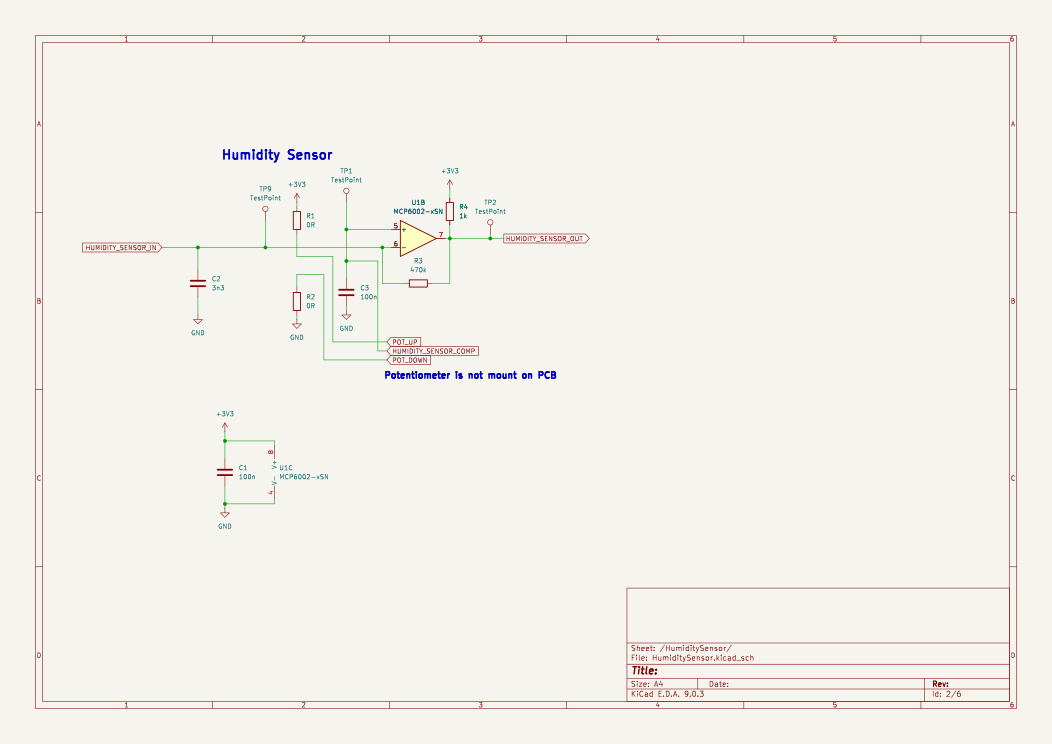
- Possibility to select the moisture level when the soil is considered dry and the watering should be started via a potentiometer
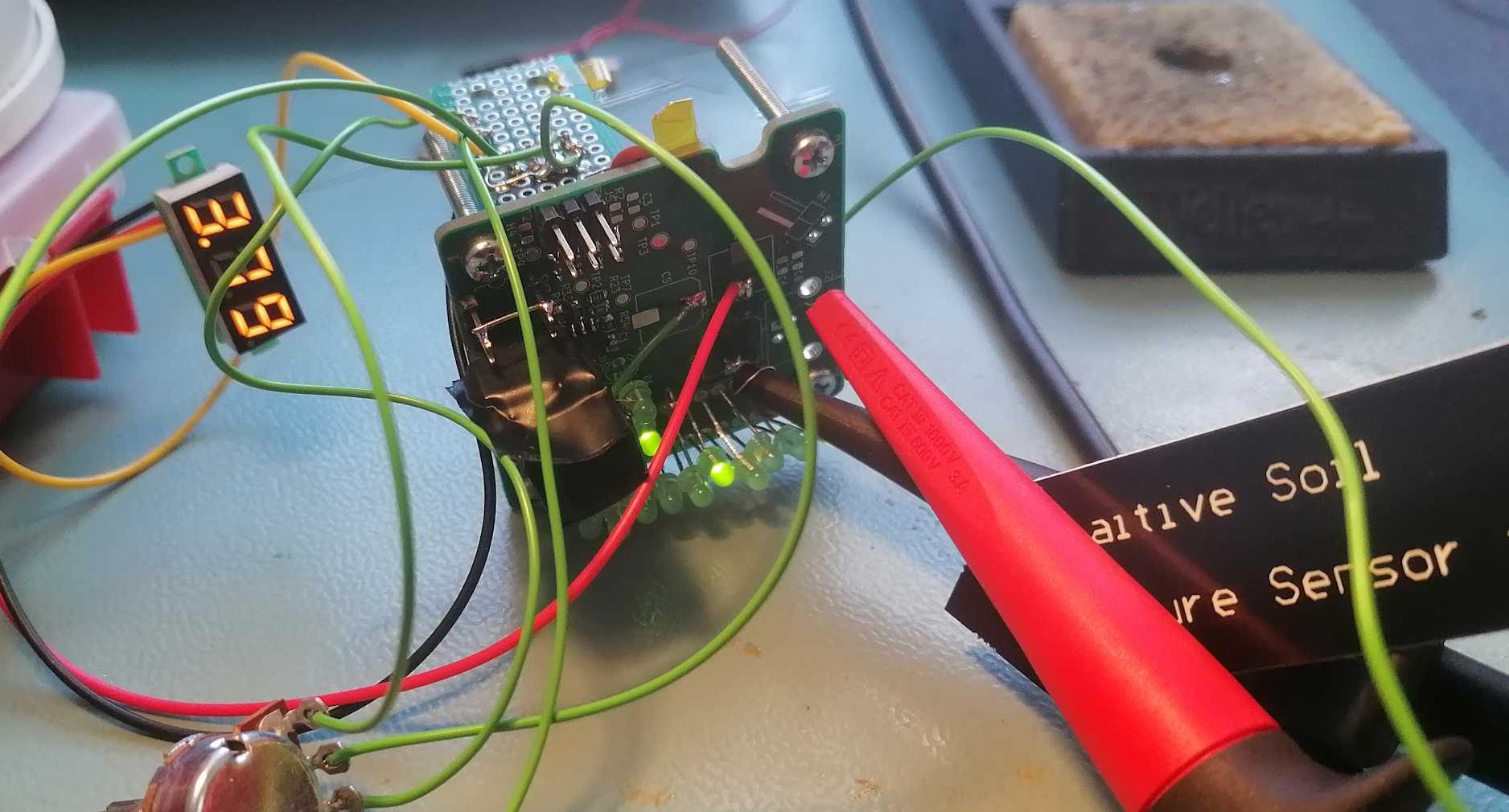
Device Description
The device is simple and contains:
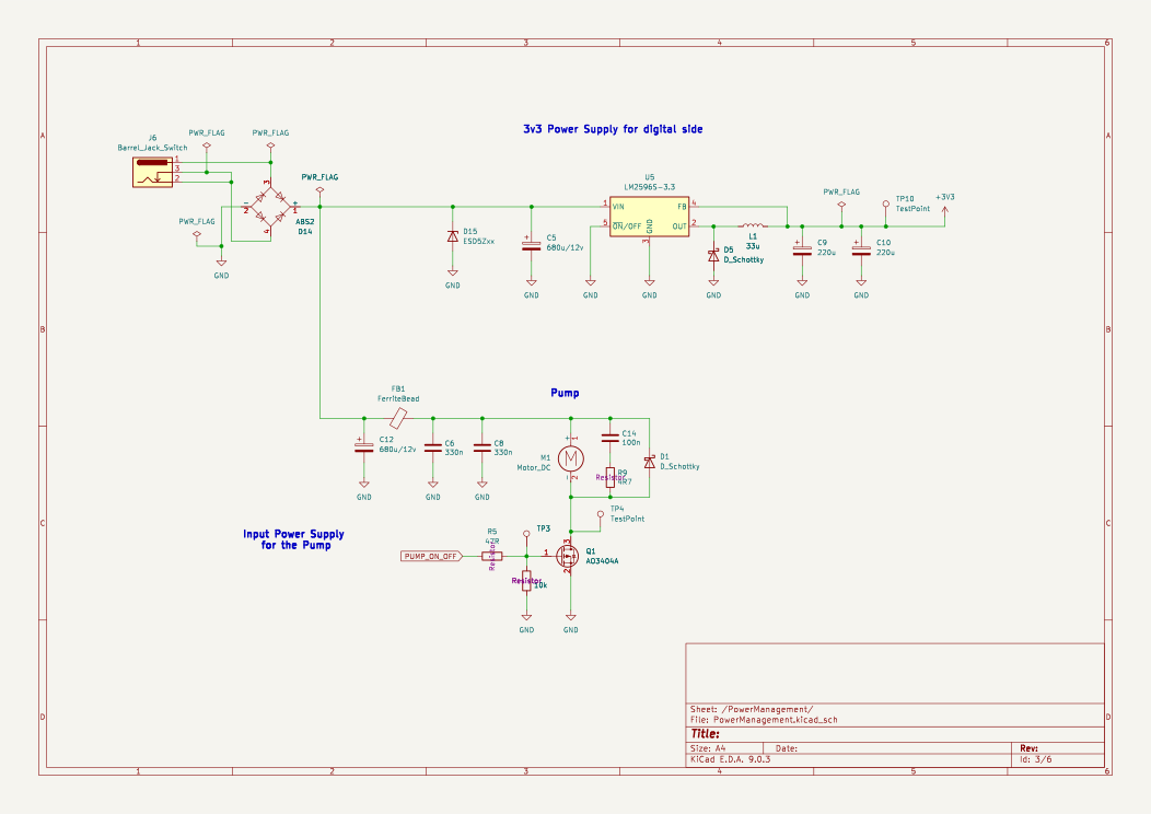
- A water pump driven by a MOSFET
- A soil moisture capacitance sensor (from AliExpress). Using a capacitance-based sensor over a resistance one has the advantage of avoiding probe corrosion due to electrolysis.
- An LCD display showing the current humidity level and the humidity threshold to start watering, and a button to change what is displayed.
- A bargraph showing how long the watering should take, and a button to change this value. Also, a potentiometer to select the level when soil is considered too dry.
I was thinking that water won't disperse immediately into the entire soil volume when the pump starts, so the sensor might still report that it's dry if checks are too frequent. This could cause the device to water the plant multiple times in a short period.
To fix this, I think the firmware will check every hour if the soil is dry and only then start watering. One hour should be enough for the water to dissipate.
Other problem is that the PIC10F200 by itself doesn’t have enough pins to make something usable with it.
In the first version (never built) to fix that I've used the 74HC595, which is a serial-to-parallel output chip, and the 74HC4052, which is a multiplexer (many inputs to one output). The PIC10F200 would drive the 74HC595, and the 74HC595 would set the needed output pins and also configure the 74HC4052. I found this idea really cool, but after thinking about it, it might be too much work for such a small chip. I don't know.
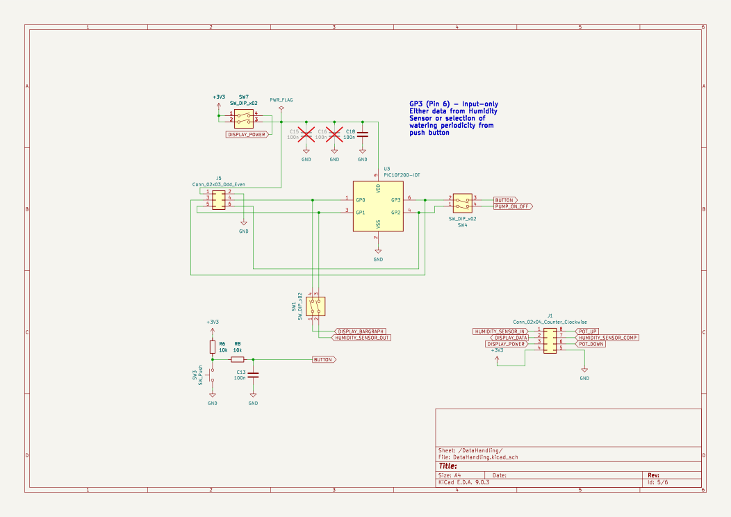
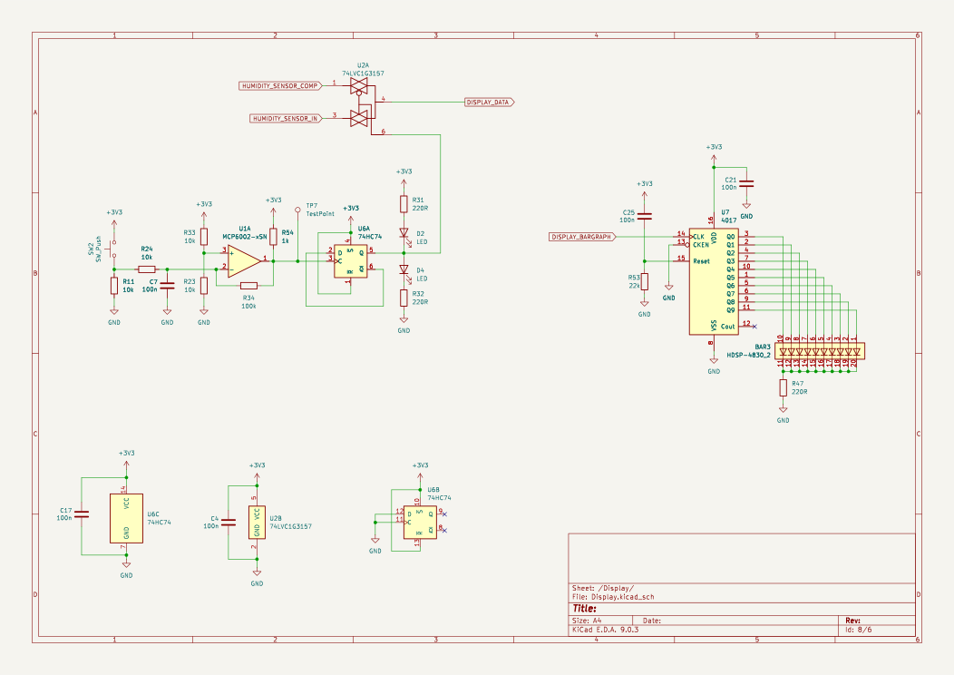
Second version (built and presented here) is much simpler. Selecting what is shown on the LCD display is done using a button connected to a 74HC74D (D-type flip-flop) and then to a 74LVC1G3157DW (analog switch) - all done outside of the microcontroller, no code needed.
The bargraph is driven by a CD74HC4017 (decade counter), which is much easier to control (need only one pin from PIC microcontroller). There is only one button connected to the PIC10F200 for selecting how long the pump runs when the soil is dry. When the user pushes it, the duration increases; when it reaches the maximum, it rolls over to the minimum value.
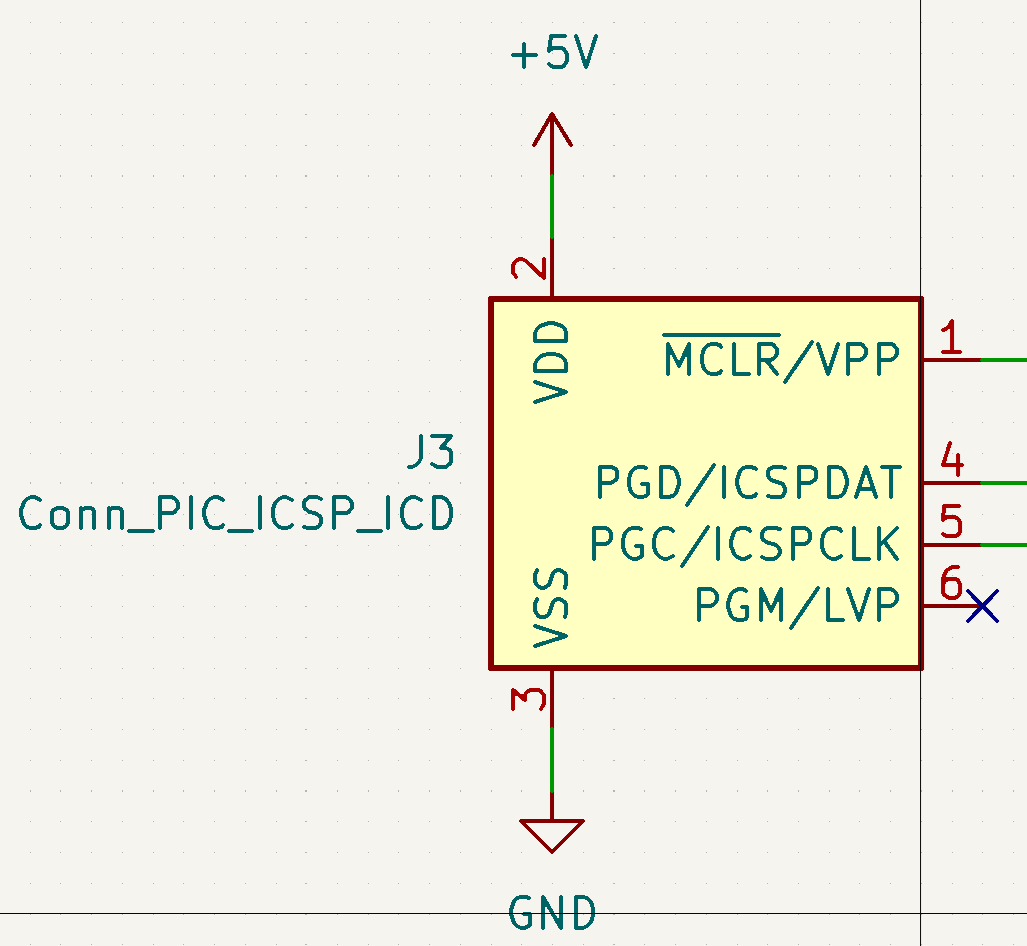
Circuit
![]() Software
Software
 Software
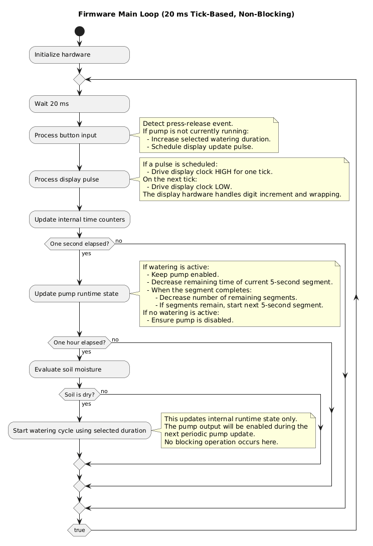
Software is written in PIC-AS assembler dialect.
Flow diagram is shown below.
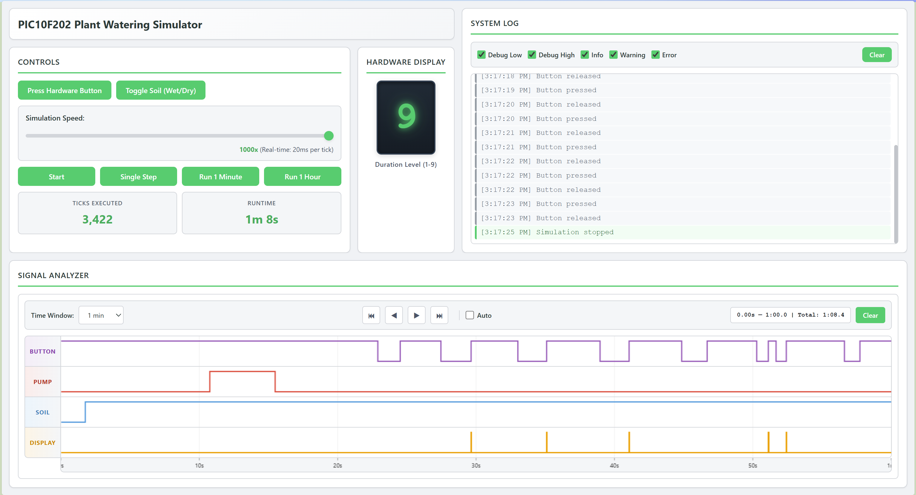
Simulation
The software can be run in a web browser to speed up development (no need to flash the device, soil humidity can be simulated as wanted, etc.).
Mechanic
A chassis to hold all elements together was modeled using OpenSCAD and FreeCAD; more info can be found in this project log entry.

 Colin O'Flynn
 Anders Helgesson
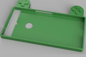
 Maave
Maave
 Tom Meehan