Robert Gawron
-
Mathematically proving code correctness - Formal Verification using Frama-C
03/18/2026 at 18:30 • 0 commentsI've found a really interesting but niche way to validate firmware, which is formal verification.
I think the easiest way to describe it is by comparing it to unit tests (in practice they compliment each other) In unit tests, we call the tested method with a set of inputs (for example, function arguments, values of global variables, etc.) and we verify the correctness of the outputs after the function call.
Code coverage says what percentage of the function lines were executed during those tests; ideally, it should be 100%. If coverage is 100% and all results are OK, then the function is fully tested. The issue is that we tested each branch at least once, but did we test all possible branch patches?
Formal verification, on the other hand, works in a way where we define a set of inputs - each should be unique - and they should cover all possible inputs, and for each, we define the output. But what is cool is that we don't have to (and many times shouldn't) define exactly what the variable value is.
We can just say if it's "bigger than 0," for example, and for all values that could be stored in the variable, the verification software will mathematically/magically check if the expectation is correct. This is stronger than a unit test because we test not only one value but all possible values that meet the criteria. Because we test all possible criteria, we test all possible inputs for the function.
An open-source tool called Frama-C can do that. It also has a GUI for looking at the results (Ivette). I've integrated it all into a Dockerfile, so I don't have to install anything locally (except Docker, but I use it in all my projects anyway). You can take a look here.
Let's now compare a unit test and an equivalent formal validation proof. The proof is in the comments above the function, Frama-C recognizes it and analyzes it.
We have two branches in the code - either the soil is dry or moist - so we have two behaviors, each specifying what its requirements are and what will happen. The two lines at the end specify that for this function, we have covered all possible branches.
/*@
    requires data.pump.configured_duration_level >= WATERING_PUMP_DURATION_LEVEL_MIN;
    requires data.pump.configured_duration_level <= WATERING_PUMP_DURATION_LEVEL_MAX;
    requires GPIObits.GP1 == 0 || GPIObits.GP1 == 1;
    requires data.pump.remaining_cycle_levels > 0
        ==> data.pump.level_remaining_seconds > 0;

    assigns data.pump.remaining_cycle_levels,
        data.pump.level_remaining_seconds;

    ensures data.pump.remaining_cycle_levels > 0
        ==> data.pump.level_remaining_seconds > 0;

    behavior soil_dry:
        assumes GPIObits.GP1 == GPIO_LEVEL_HIGH;
        ensures data.pump.remaining_cycle_levels ==
            data.pump.configured_duration_level;
        ensures data.pump.level_remaining_seconds == WATERING_PUMP_STEP_DURATION_SECONDS;

    behavior soil_moist:
        assumes GPIObits.GP1 == GPIO_LEVEL_LOW;
        assigns \nothing;

    complete behaviors;
    disjoint behaviors;
*/
void watering_handle_sensor_check(void)
{
    if (GPIO_IS_HIGH(GPIO_SOIL_SENSOR_INPUT))
    {
        data.pump.remaining_cycle_levels = data.pump.configured_duration_level;
        data.pump.level_remaining_seconds = WATERING_PUMP_STEP_DURATION_SECONDS;
    }
    else
    {
        WATERING_LOG_DEBUG_HIGH("Soil check OK - moisture sufficient");
    }
}
If you want to look at the equivalent unit test for this function, here is the link.
I've done formal verification of all the business logic in the firmware (or at least that's what I think; this is the first time I've done it). You can find more proofs in the main.c and watering.c files.
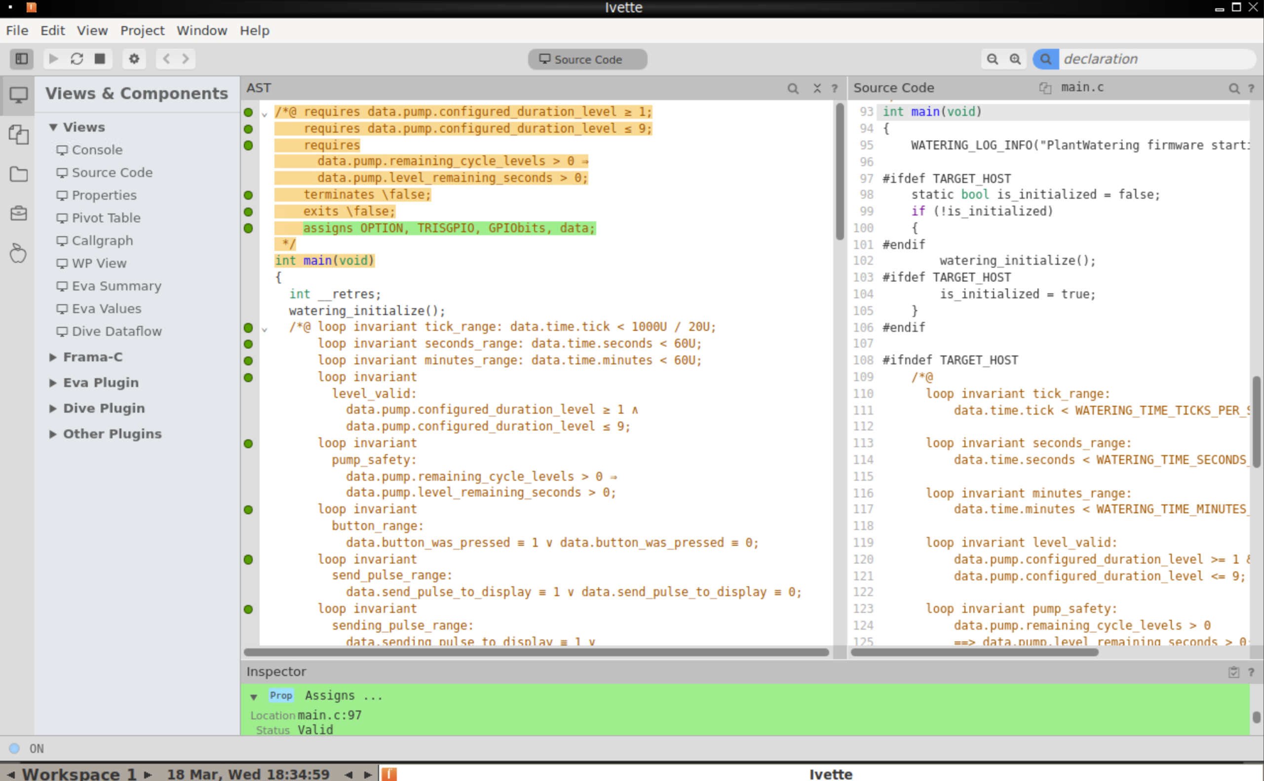
There is also a graphic tool called Ivette to inspect the results. Basically, it works in a way that for each proof, it gives a dot; green means it was verified. For example:
![]()
The idea, although it looks cool, is niche because it's harder to use than unit tests; it's mostly applied in the military, aerospace, or medical sectors.
-
Firmware Emulation in the Browser Using WASM
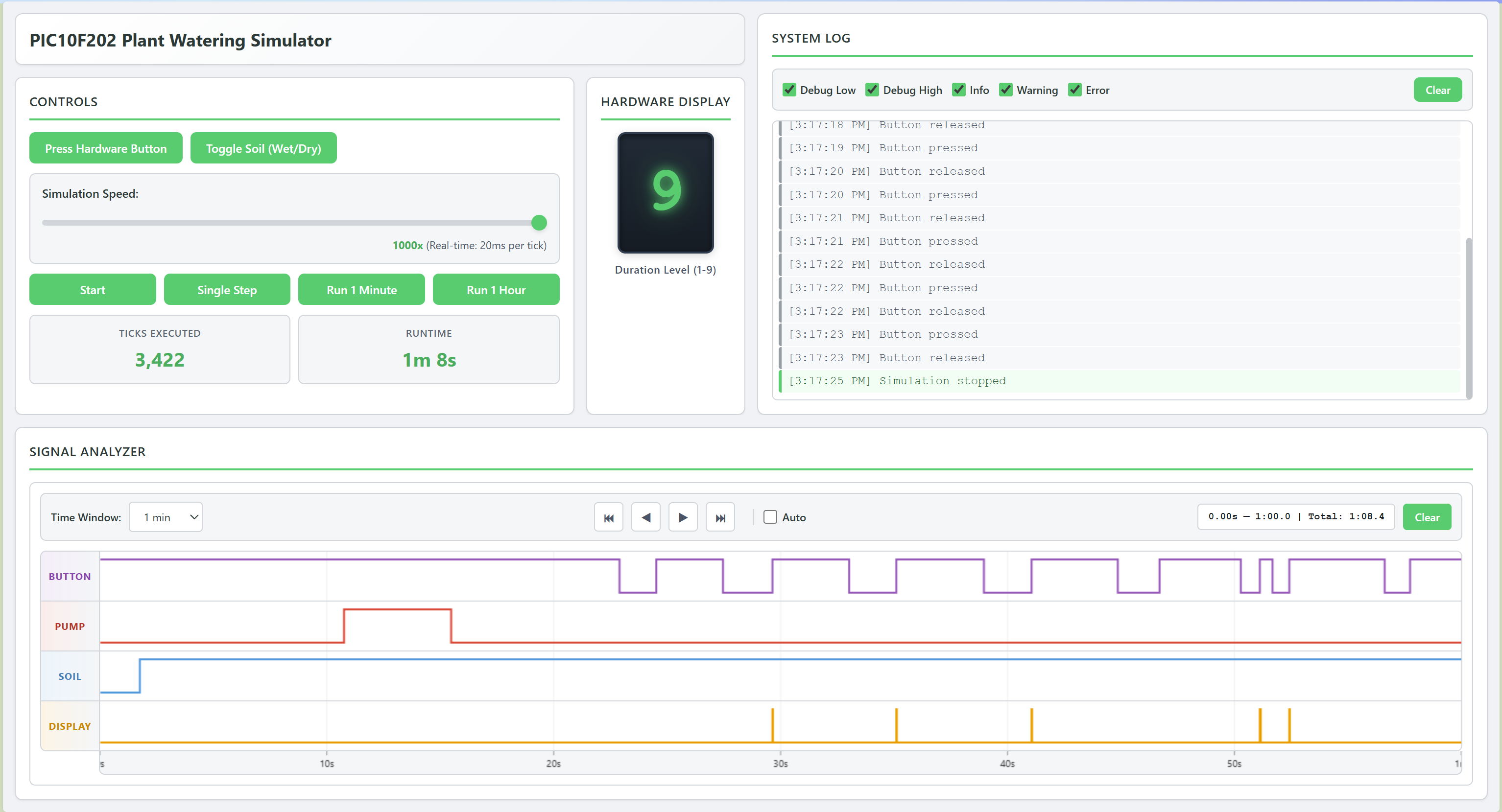
03/08/2026 at 16:13 • 0 commentsI've built a version of my C firmware that runs in the browser. I stubbed the hardware peripherals using JavaScript, I can run, test, and validate high-level logic directly in the browser without needing to flash the real device.
![]()
This approach has several benefits:
- I can simulate soil humidity changes and similar inputs, making firmware validation much easier.
- It allows for logging directly from the firmware (which the hardware build can't do, since the PIC10F202 lacks a UART peripheral).
- Additionally, I have coded a small logic analyzer that displays the state of all the microcontroller's GPIOs and allows me to set input pins, simulating data from push buttons and soil sensors.
The simulation setup includes:
- High-level firmware code: this does not communicate with hardware directly, but instead uses a Hardware Abstraction Layer (HAL).
- Tiny HAL in firmware: when built for hardware, use real peripherals; when built for emulation, use JavaScript hooks.
- WASM Compilation: the firmware is compiled from C to WebAssembly using Emscripten, which also generates the necessary JavaScript glue code. The build process uses Meson (I wanted to try something new, could be cmmake instead), and for easy launching, I use the just tool - it’s excellent for automating one-liners, and I’ll definitely be using it more often!!
- TypeScript application: this orchestrates the firmware via the aforementioned hooks and handles the web page display.
- HTML and CSS: The frontend structure for the web interface.
You can check the source code on project's GitHub.
Ultimately, WASM is quite an interesting technology!
-
Coding in C for the PIC10F202 chip
03/01/2026 at 17:05 • 5 commentsI've rewritten firmware from assembler to C and.. the binary size is actually smaller now :)
Interesting things I've found:
- PIC10F202 doesn't have multiplication, division, or modulo instructions. If they are used in C code, the compiler will generate assembly using what instructions are available - it will emulate the needed instructions. This creates huge code. Long story short: avoid at all cost in implementation. This was quite amusing for me; I didn't expect algorithmic challenges on such a small chip.
- Variables that are bigger than a byte generate huge binary size as well. All variables should be no bigger than a byte.
- MPLAB IDE already has stdint.h and stdbool.h - all types are there like uint8_t and bool. No need to create own types, very nice. Note that PIC chips don't use gcc/clang compiler, so this is not that obvious.
- The chip has a hardware call stack limited to only two levels deep. One has to carefully look at which functions call which ones - if the level is more than two, at runtime the app will crash. One trick to deal with that is to use function-like macros. Another is to set a flag instead of calling a function, and then in the top method call the function.
- A cool trick I've learned people do to save space is to declare all variables in one global structure. Is it God object antipattern? Probably yes :) This way all bool variables can be kept on a single byte, saving space. Bit fields.
- Although the chip doesn't have multiplication or division, the compiler is smart enough to compute things if they are constants, so multiplication is ok to use in #define constants.
- MPLAB IDE has C99 standard for those chips, but they have also implemented _Static_assert - very handy for static assertions.
PS; look on the new code I made while learning all this, would be great to get feedback:
-
HW 1.0 thoughts and plans
02/07/2026 at 10:46 • 0 commentsThis version is a success, but:
- The firmware for PIC10F202 could be written in C instead of Assembler. I will try to rewrite it.
- The whole idea of changing what is shown on the display using a D-type flip-flop + analog multiplexer doesn't work, it's overcomplicated and overpriced. In the future, I will just use two LCD modules. They are cheap.
- It takes time to solder and protect (using hot glue) the connectors for the potentiometer, humidity sensor, and LCD display. Also, hot glue everywhere doesn't look very professional :) I plan to use Micro JST-XH connectors instead. There is also pinces-like tool to form cables for it, I don't know the name.
- The 4017 chip + bargraph works (for showing how much water will be dispensed next time), but I have found a better way. The same can be achieved with a CD4026 + 7-segment display. The CD4026 is nice because it only needs pulses to be driven, so only one GPIO is still needed for it.
- In the meantime, I have found a nice open-source project called Topola - it's a topological router. I will use it in the next design. The PCB is simple, so it's a good sandbox for it.
- I have also found the KiBuzzard add-on for KiCad, which should be great for labeling test points and connector pins.
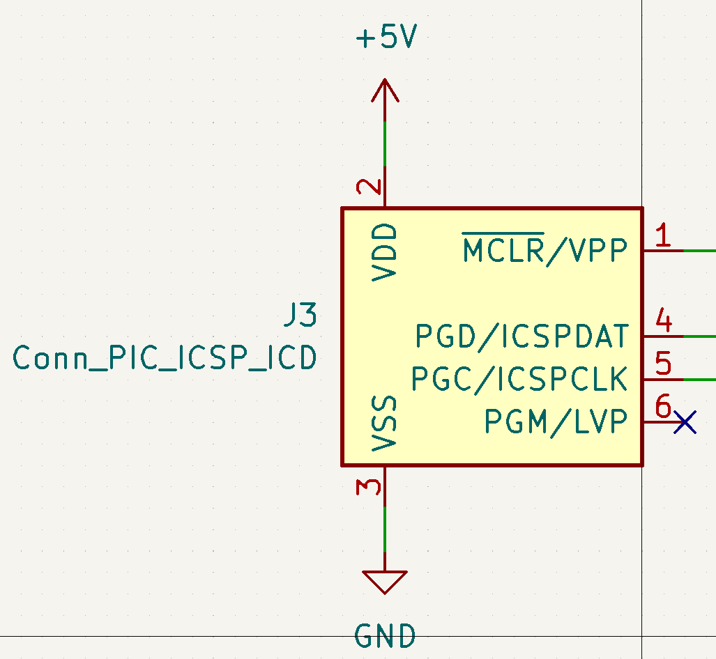
- KiCad has a connector for a PIC ICSP programmer (component name: Conn_PIC_ICSP_ICD). I will use it so that the programmer can be plugged directly into the board—no need for jumper wires, which are error-prone.
![]()
-
First steps with PIC microcontrollers
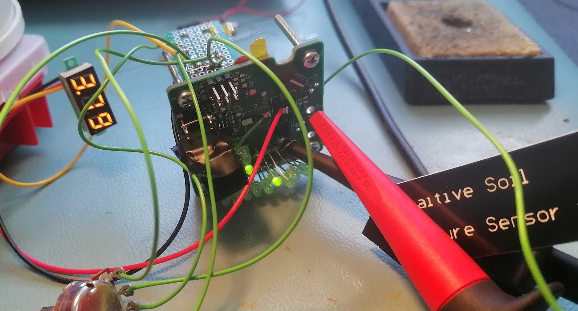
01/27/2026 at 15:51 • 3 commentsI'm soldering/programming this device and things I've learned so far about PIC microcontrollers:
- Those low-end chips can be programmed in many variants of assembler dialect. There is at least MPASM, PIC-AS, GPASM. I've chosen PIC-AS because it's available in MPLAB IDE (environment by Microchip for writing software for PIC microcontrollers) and seems to be more modern. I don't get why they created a new version of assembler dialect, what was wrong with the older MPASM?
- MPLAB IDE has dropped support for AFAIK the most popular hobbyist level programmer - PICKit3. There is some added/kept support for it in MPLAB IPE tool, but for me PICKit3 doesn't enumerate in available devices there.
- There is an open source alternative for flashing those chips (PICkitminus) and it works fine.
- Microchip provides their IDE based on NetBeans (NetBeans=Java=slow), but they also created a bunch of plugins for VS Code. The project needs to be once created in MPLAB IDE and then it can be imported and built in VS Code. Nice.
- The mentioned PICkit tool has a command line version, so I think it's possible to script it from VS Code to flash the chip automatically.
- VS Code AFAIK doesn't have a nice plugin to color PIC-AS dialect of assembler for those chips, the best what I've found is this plugin.
![]()
-
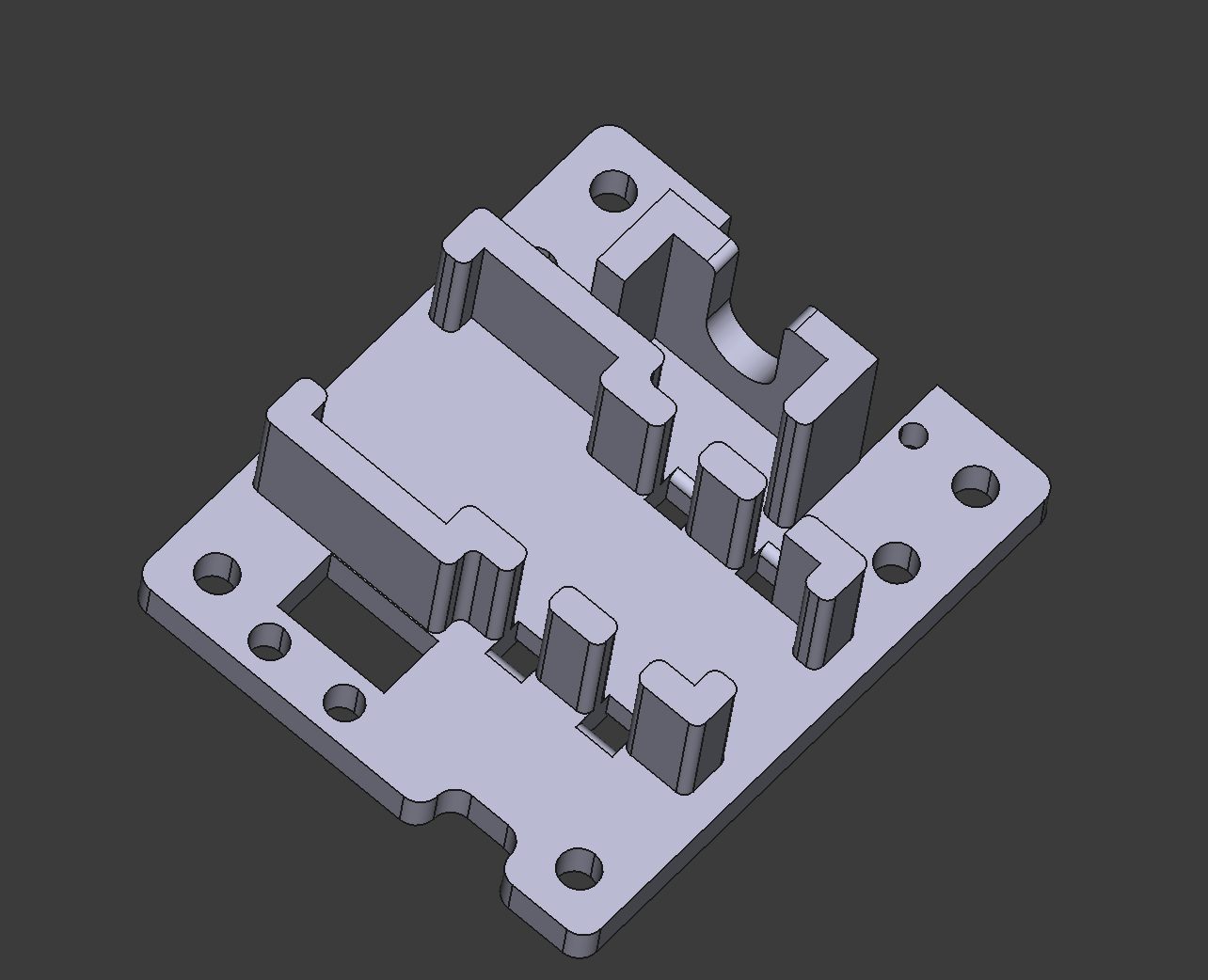
A 3D Model Made Using OpenSCAD for Parametric Design and FreeCAD for Finishing Touches
09/14/2025 at 13:57 • 0 commentsI tried to make a 3D printable holder using only open-source CAD tools: FreeCAD and OpenSCAD. While the model is simple, the tools are not easy to use, but I finally made it, and I think it's quite interesting how to do 3D modeling without needing paid tools. In this post, I will share how to use FreeCAD and OpenSCAD, using their strong sides and avoiding their weak ones.
First, OpenSCAD: it's a programming language to create 3D models. Everything starts from simple 2D shapes like rectangles and circles. They can be added, subtracted, or moved to create more complex shapes. Then, those shapes can be extruded (we give them size in the Z-axis), and the resulting 3D shapes can again be added, subtracted, or moved to create even more complex shapes. Because it's a programming language, it's easy to parametrize the design - like any language, it has variables.
It's a great tool but has its limitations and weird behaviors. By default, if a variable is not initialized, the compiler will try to ignore it and continue, but this leads to incorrect models (if the variable was there, it had some purpose, like shifting the shape a bit in some direction, etc.). Fortunately, this can be changed in the settings.
Another thing I found is that it's easy to make messy models with a lot of duplication - it's a language so it's easy to write bad code. Fortunately, the project can be split into separate files and linked later using the include directive. Also, it's good to use the module directive to split the design into separate parts instead of doing everything directly with built-in primitives like rectangles and circles.
Other limitations is that it's impossible to add dimensions to rendered objects, so it's hard to visually check if everything is modeled correctly. In FreeCAD, it's simple - all you need to do is select an edge, click the dimension tool, and the length is visualized.
Last but very annoying: it's hard to model fillets (rounded corners), while in FreeCAD, again, it's trivial.
My idea was then to make a model in OpenSCAD and import it to FreeCAD, and that's what I did. Why not do everything in FreeCAD? Well, FreeCAD's user interface is horrible. There are so many weird things in it that I could make an entirely new post just about it, but I’ll just mention a bit of what annoys me the most.
FreeCAD’s GUI is bad regarding how it handles parametrization. I will add that the idea of parametrization is that instead of hardcoding dimensions in designs, a parameter can be used - one parameter can be used in many places, making changes easier to make. It’s a great idea but poorly implemented. It’s not possible to add comments explaining what the parameter represents, no option to link to a datasheet where it comes from, etc.
But let's get back, once the model in OpenSCAD is done, even if it renders perfectly in OpenSCAD, it can fail to import into FreeCAD. I found that FreeCAD doesn’t like it when the OpenSCAD "mirror" directive is used on 2D objects. FreeCAD, of course, won’t say where the problem is during the import. Again, horrible software! By the way that also when it's a good to split the OpenSCAD design into separate files/modules, each file split into modules, to be able to temporarily comment out the code and see where the problem is.
The import of the OpenSCAD project has a trap, too. FreeCAD has workbenches (kind of like perspectives in Eclipse), and there is a workbench dedicated to OpenSCAD, but the import fails if an OpenSCAD file includes other OpenSCAD files. However, it works when importing by File -> Import. No need for OpenSCAD workbench.
Then, the fillets. Some are impossible because FreeCAD will crash :) But most are possible. Fillets can be added either in the "Part" or "Part Design" workbenches. The "Part Design" workbench can’t directly work with imported OpenSCAD projects, so the fillets don’t work (at least not easily). Fortunately, the "Part" workbench works. Also, the "Part" workbench has a dimension tool to measure edge lengths, although I wasn’t able to measure hole radii.
So that’s it: we have a project done in OpenSCAD and then imported into FreeCAD to add fillets and check dimensions. It should be good. If the OpenSCAD project is modified, it needs to be reimported into FreeCAD, and the fillets need to be reapplied, but I found it can be done quickly (at least for a simple project).
I finally made my design and learned a lot. It’s my first one, so probably not the best, but I’m happy.
What are your experiences with OpenSCAD and FreeCAD?
![]()
Home Plant Watering System Based on the PIC10F202
A home plant watering device based on a simple 8-pin PIC microcontroller and 74HC chips.