 Ioan Larionov
A compact switching power supply designed for test automation and HIL setups.
-
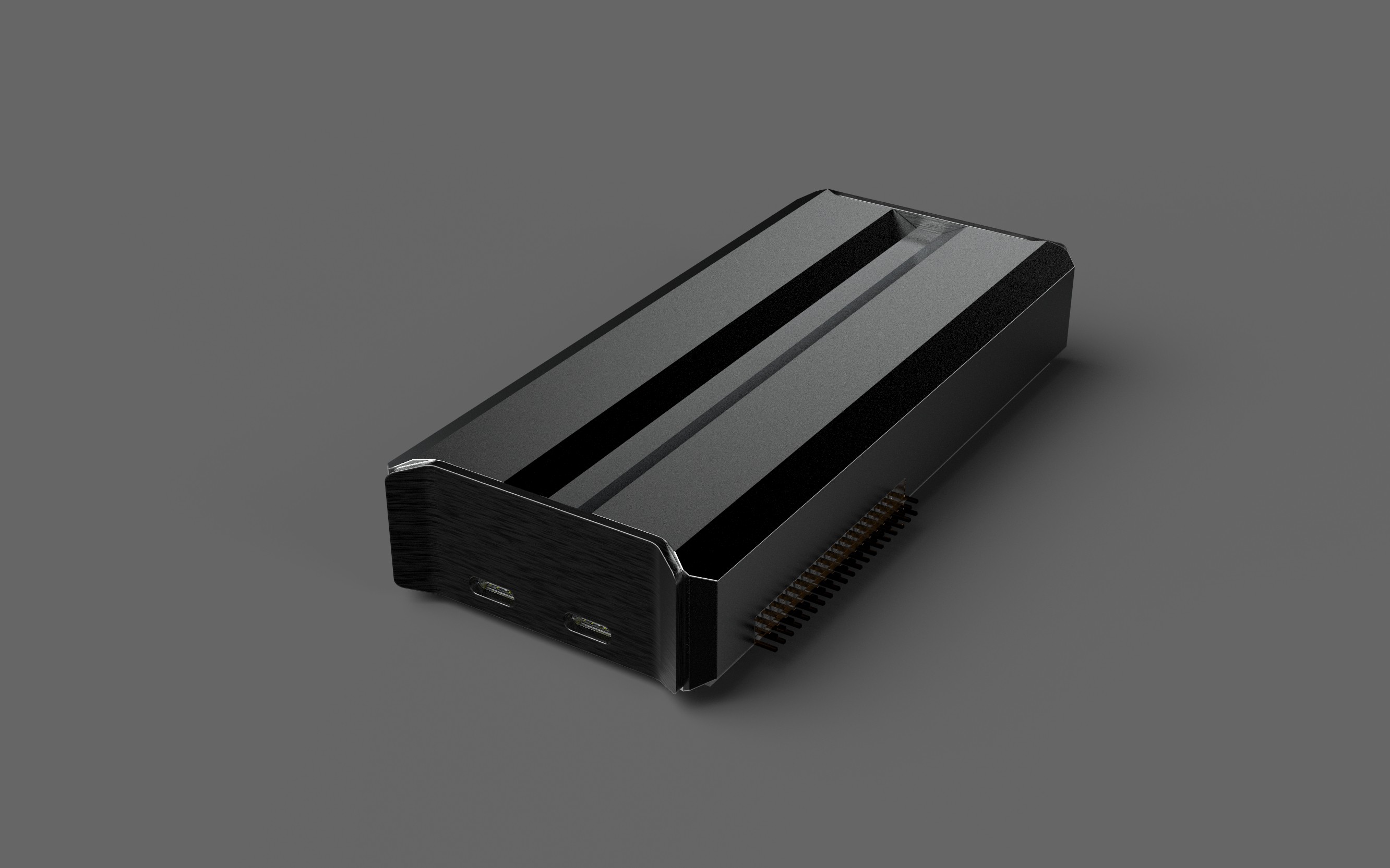
Powered from USB-C PD (100 W)
-
Controlled via USB with a clean Python library
-
Built with Open Source Hardware & Software principles
Our goal is to create a new category of instruments: affordable, open, and designed specifically for testing.
Features
-
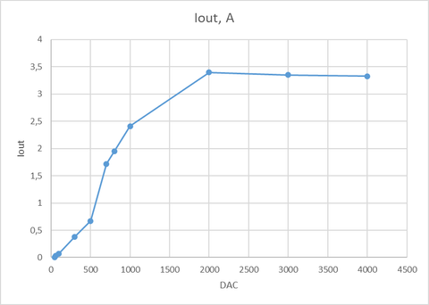
Output: 0–32 V / up to 3 A (96 W max)
-
Ripple: < 30 mVpp, < 2 mA RMS
-
Protections: OVP, OCP, OPP, OTP
-
Measurement resolution: 10 mV / 1 mA
-
Control: USB-B (SCPI, custom firmware mods), PLD connector for extensions
-
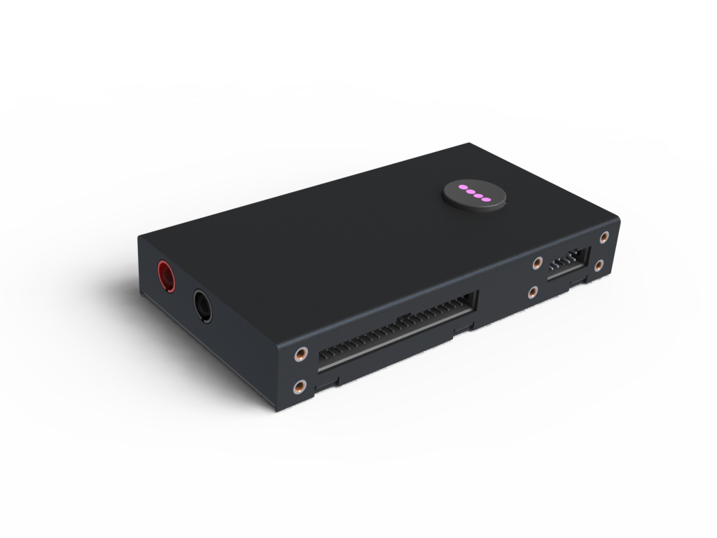
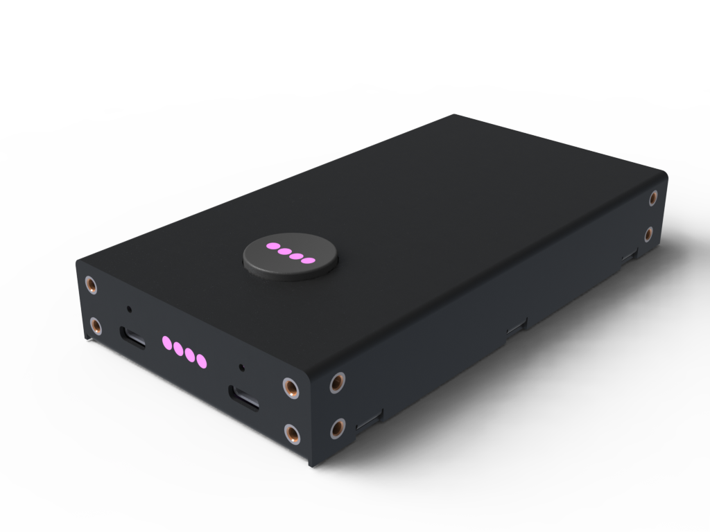
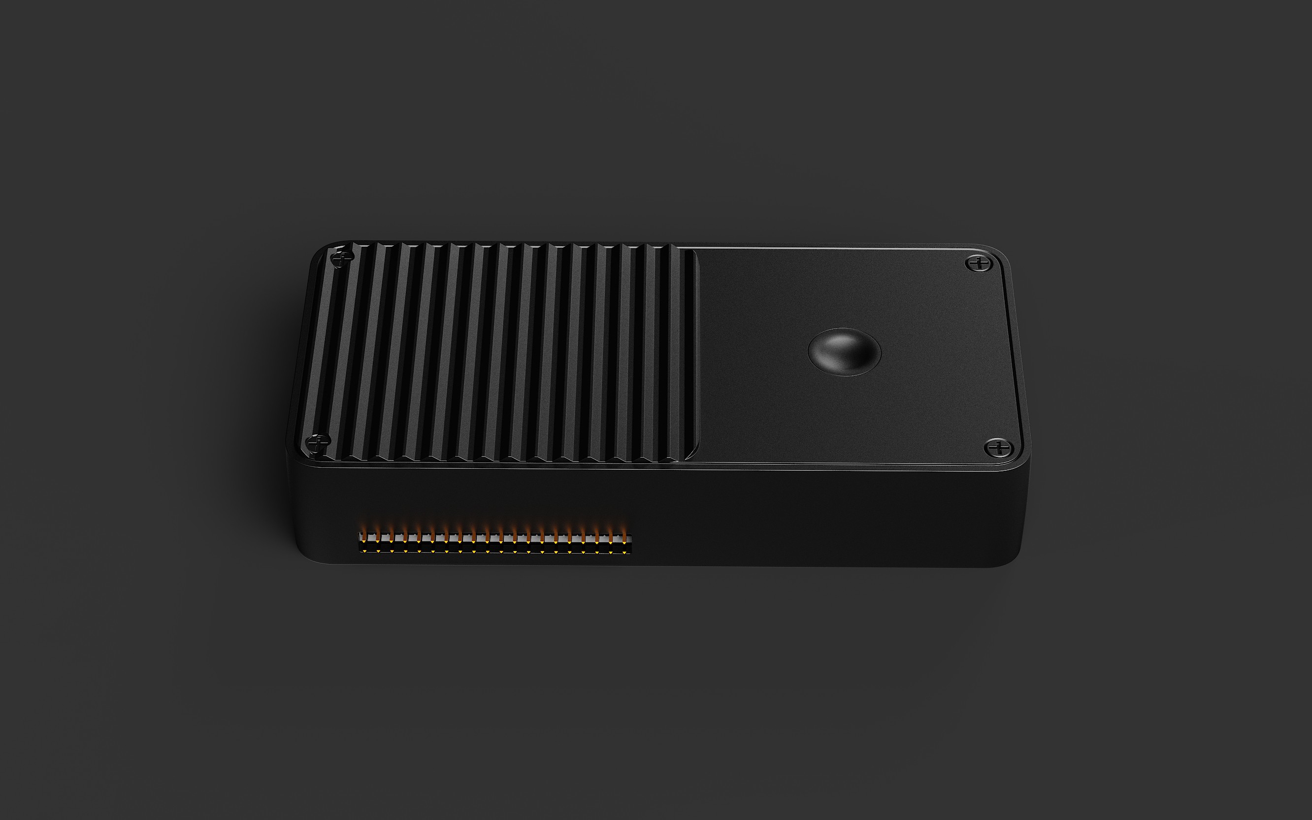
Expandability: LEDs for status, button for manual toggle, optional module with screen/knobs
Technical Specs
Electrical Parameters
| № | Parameter | Value |
|---|---|---|
| 1 | Input | USB Type-C Power Delivery 100W |
| 2 | Output | Not galvanically isolated |
| 3 | Number of channels | 1 |
| 4 | Max output power | 96 W |
| 5 | Output voltage | 0–32 V |
| 6 | Output current | 3 A max |
| 9 | Voltage ripple | < 30 mVpp |
| 10 | Current ripple | < 2 mA RMS |
| 11 | Load regulation (10–90%) | ±0.1% + 20 mV / ±0.1% + 5 mA |
| 14 | Load recovery time | < 200 µs |
| 15 | Line regulation (±10%) | ±0.1% + 20 mV / ±0.1% + 5 mA |
| 18 | Voltage overshoot (turn-off) | < 100 mV |
| 20 | Setpoint resolution | 10 mV / 1 mA |
| 23 | Setpoint accuracy | ±0.1% + 30 mV / ±0.1% + 5 mA |
Measurements
-
Quantities: Voltage, Current, Power
-
Accuracy: ±0.1% + 30 mV / ±0.1% + 5 mA
-
Resolution: 10 mV / 1 mA
Protections
-
Overvoltage (OVP) — configurable
-
Overcurrent (OCP) — configurable, trip < 10 ms at 2× load
-
Overpower (OPP) — configurable
-
Overtemperature (OTP)
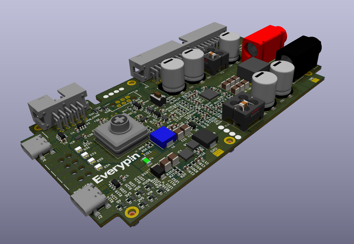
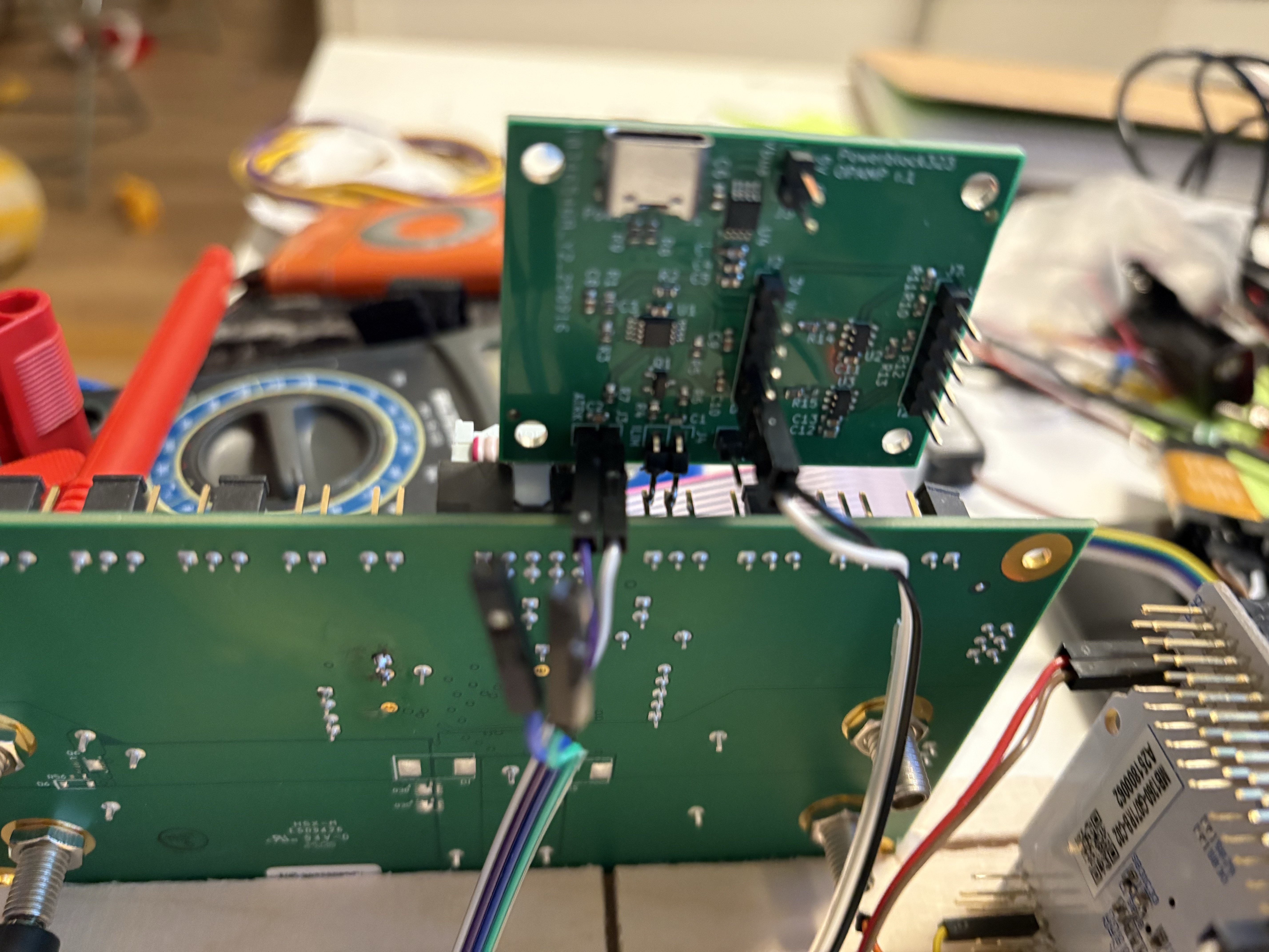
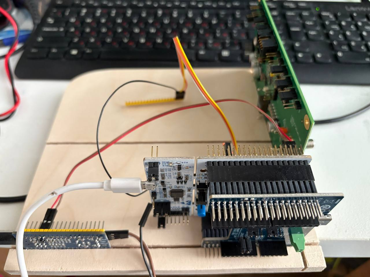
Structure
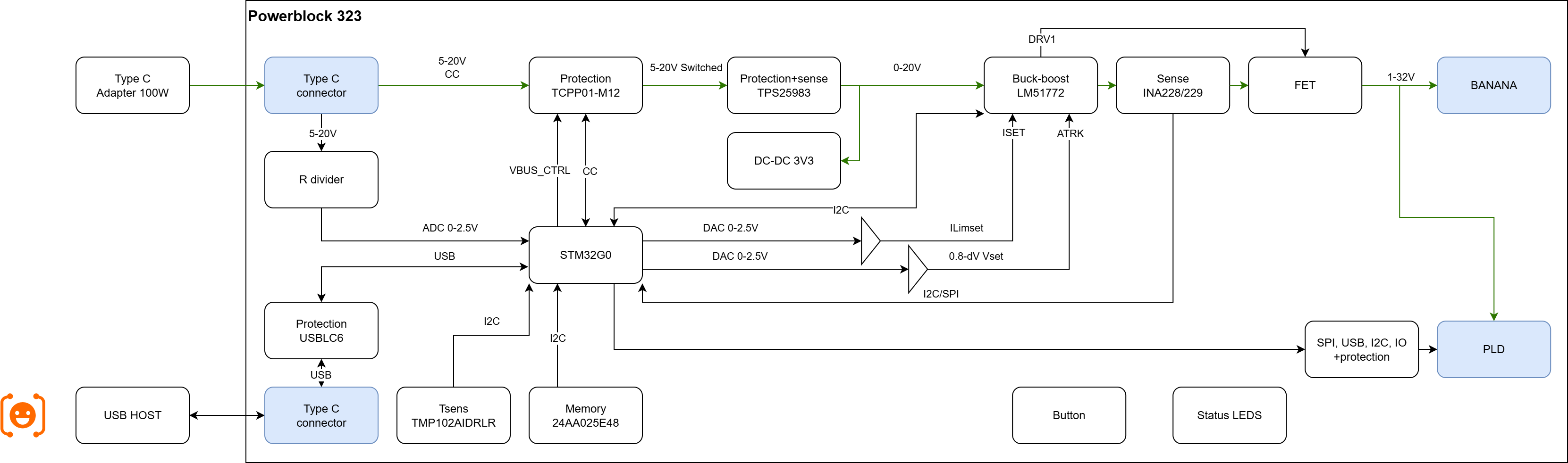
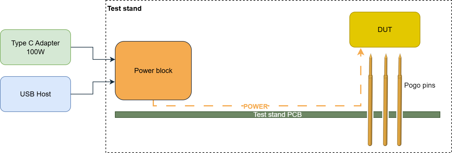
- USB Host - control device (PC, single-board computer, laptop, etc.),
- DUT - load, device under test
- Type C Adapter - any USB-C power source, e.g., mains, power bank, laptop, phone.
- The MCU controls all parts of the unit. This makes it possible not only to control the source from a PC, but also to load presets according to a predefined algorithm and link the power supply to external events.
- PLD connector - a universal connector that provides input and output power, USB control, microcontroller interfaces, and logic power.
Of course, this is a specialized power supply, and we do not intend to replace laboratory power supplies. Let's talk more about the application options.
Use Cases
In Test Stands
-
Automated cycling, no manual knobs or displays
-
Board-to-board or internal wiring power delivery
-
Multiple modules for multi-voltage DUTs
-
PC inside the fixture, USB control via PLD
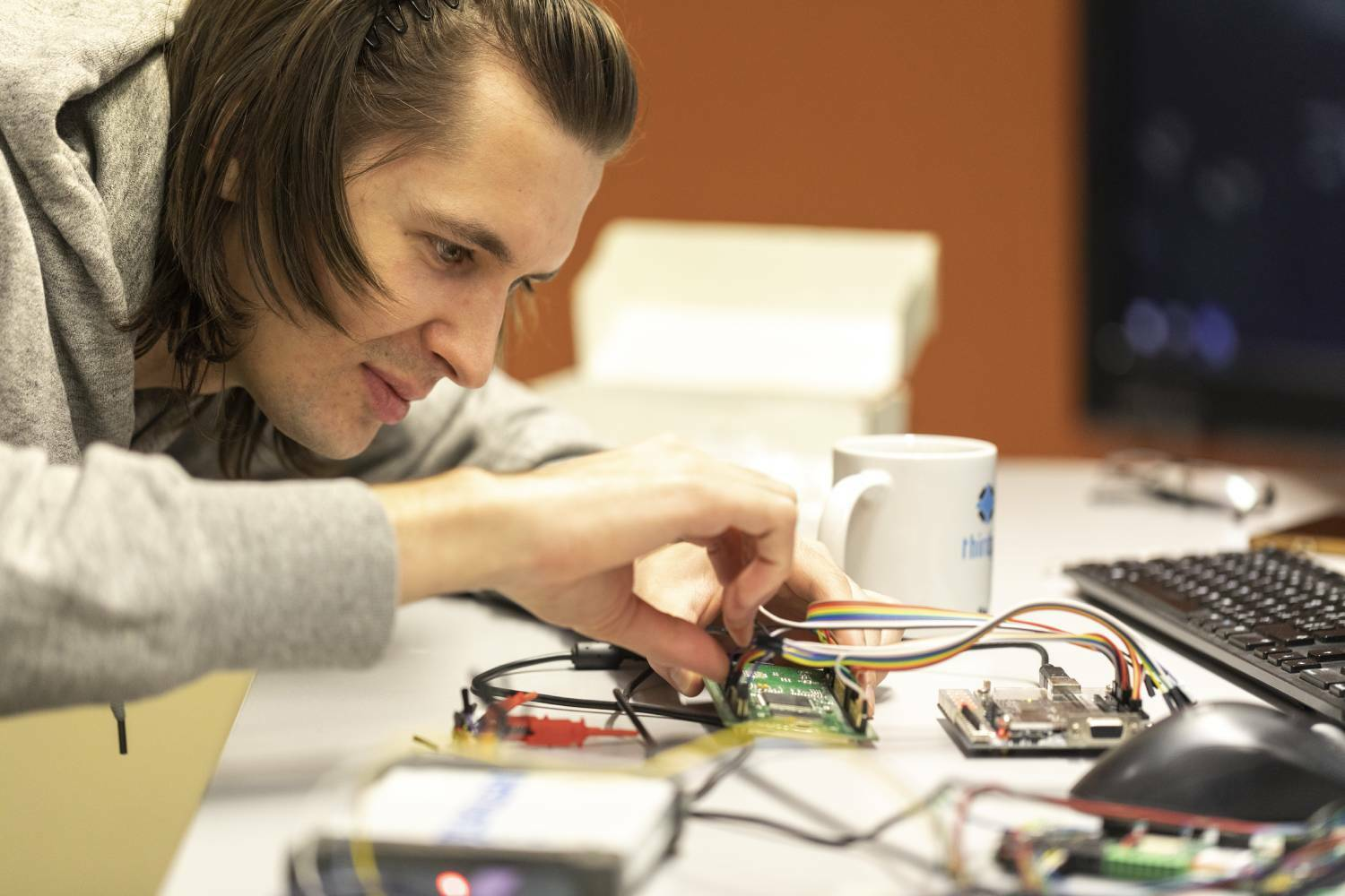
On the Desk
-
Simple power setup for developers
-
Configured via console, Jupyter, or SmuView
-
One button, LED indicators, optional expansion with knobs & screen
Roadmap
- Collect feedback from the community
- Build and test prototypes
- Crowdfunding launch on CrowdSupply
...
N. Series of compact open tools: USB HUB, multimeter, production programmer, signal MUX, logic analyzer, DAQ...


 Arshmah Shahkar
 mircemk
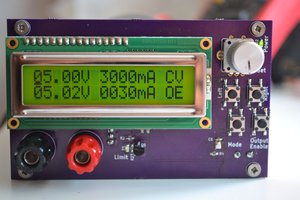
 Elia
Elia
 Sagar 001
Interesting idea! Do you have any BOM cost goals or thoughts yet?