 Joseph Eoff
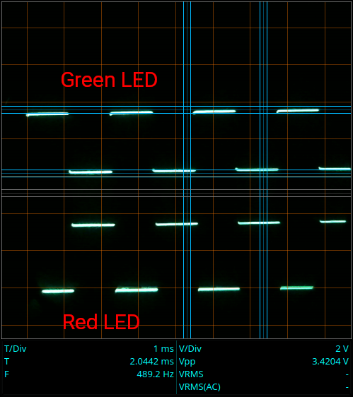
Since I had the prototype and the oscilloscope both at hand to check the oscillator signal, I went ahead and checked the LED signals.
The 7473 does a pretty decent job of squaring up the funky edges of the LM3909 signal. The outputs are nice, neat square waves.
Each alone wouldn't do you much good. The trick is when you connect the LEDs anti-parallel with the diode under test in series with them.
There is effectively an AC signal across the LEDs. Putting a diode in series cuts off one half of the AC cycle, leaving only one half to drive the LEDs pair. Which ever LED "points" in the same direction as the diode under test lights up.
As the 7473 datasheet shows, the Q and /Q outputs of the 7473 are each effectively half an H-bridge, with the /Q driven by the inverse of the Q output:
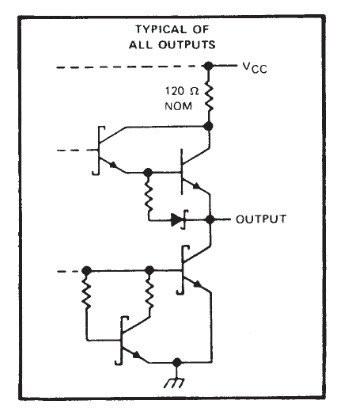
Two half H-bridges and an inverter make a full H-bridge. If there were a (very) low powered motor in there, it would reverse direction on each pulse of the clock. Instead, there are two diodes in anti-parallel in there. They light up alternately as the clock pulses.
If you slow down the clock, you can see the LEDs light up one at a time. With the fast clock I've used, they alternate faster than the eye can see - they appear to be both on all the time when the diode under test is shorted.
Discussions
Become a Hackaday.io Member
Create an account to leave a comment. Already have an account? Log In.