 Joseph Eoff
After showing how abusive this circuit is, it is now time to explain how it survives and functions despite the abuses.
1. Powered by a 9V transistor radio battery with no regulator. The 7473 receives 9V from the battery (the absolute maximum for the 7473 is 5.5V)
There are two things that go into making this work:
- The note by the battery "9V carbon zinc"
- Robustness of the IC
Carbon zinc 9V batteries have a fairly high internal resistance. The output voltage of the battery drops when loaded. If the IC tries to draw a current that could damage it, the battery simply drops the voltage. During my experiments, the voltage from the battery dropped to around 7V. That is still high, but then the robustness of the IC comes into play
The IC is rated for 5V, but there's nothing inside it really requires exactly 5V. All of the transistors will have a VCE of more than 5V. How much more, no one can say without destructive testing. More than 5V, certainly. More than 7V? Obviously, because it ran with that voltage on my workbench. More than 12V? Try it and see.
2. The LM3909 LED blinker IC has no LED to blink.
The LM3909 datasheet (https://cdn.hackaday.io/files/291791248394336/LM3909%20Datasheet%202.pdf) shows the internal circuit of the IC.
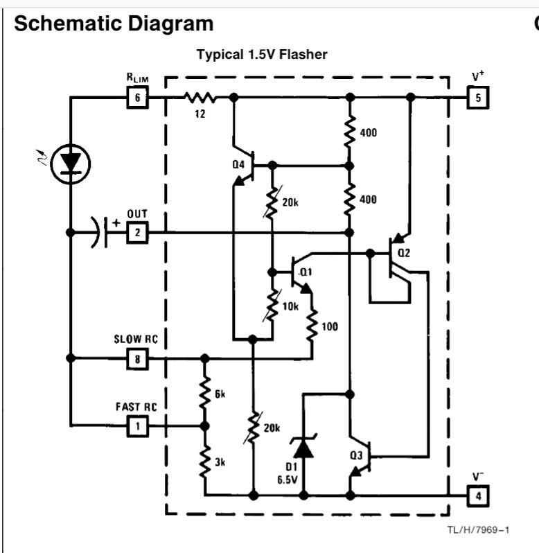
The LED plays no part in the oscillator. It runs just fine without the LED.
3. The LM3909 is powered by the leakage current from the 7473 clock input. The datasheet says it needs a minimum of 1.15V to operate. It is operating here on something less than 1V.
This is down to design specifications. The 3909 is guaranteed to operate down to 1.15V. What is does below that is not specified. If it works, cool. If not, the manufacturer just says "Oh, well. Tough. The 3909 isn't specified for that." Practically, the LM3909 blinkers were used with a single 1.5V cell, and ran to exhaustion. If it ran with a battery discharged below 1.15V, fine. So much the better. It just wasn't guaranteed.
As for just where the power comes from, that is given by the design on the inputs on the 7473:
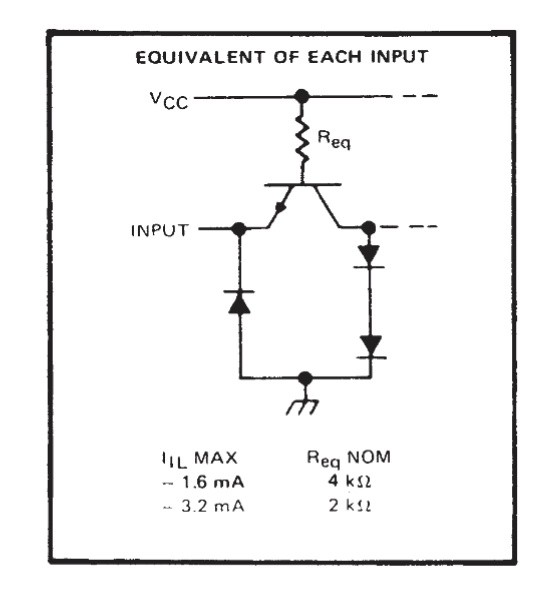
The clock input is the emitter of an NPN transistor. Current flows from VCC, through Req, through the base of the transistor, and out of the clock input. Depending on the exact value of Req, you get anywhere from 1.6mA to 3.2mA out of the input. The LM3909 datasheet says it draws a maximum of 0.75mA. That load pulls the voltage down considerably, but still leaves enough voltage for the 3909 to operate (though far outside of its specifications.)
4. The clock signal to the 7473 is a 0.7V peak to peak signal. By the datasheet, a low is maximum 0.8V and a high is minimum 2V. Somehow, 0.7V is enough to trigger the clock.
I strongly suspect that the 0.7V does not oscillate between 0 and 0.7V, but rather that it bounces between something just over 0.8V and something somewhat below 0.8V. I needed to check the offset on the clock signal, but didn't do it. I won't be able to get to my workbench to check this before the contest deadline, so this will have to remain speculation for now.
5. There's no decoupling capacitor for the 7473.
For TTL circuits, it is recommended to have a 100nF capacitor across the power leads of each IC. In this case, it isn't needed. The decoupling capacitor is there to prevent power rail glitches from a fast switching IC from disturbing other ICs. There are no other TTL ICs in this circuit, and no fast signals at all. We can safely leave out the decoupling capacitor.
6. The 7473 is driving the LEDs directly, with no current limiting resistor. This exceeds the output current limit for the 7473.
7. The LEDs are driven directly from the 7473 with no current limiting. This exceeds the LED current limits.
These two have a common cause: The output circuit of the 7473:
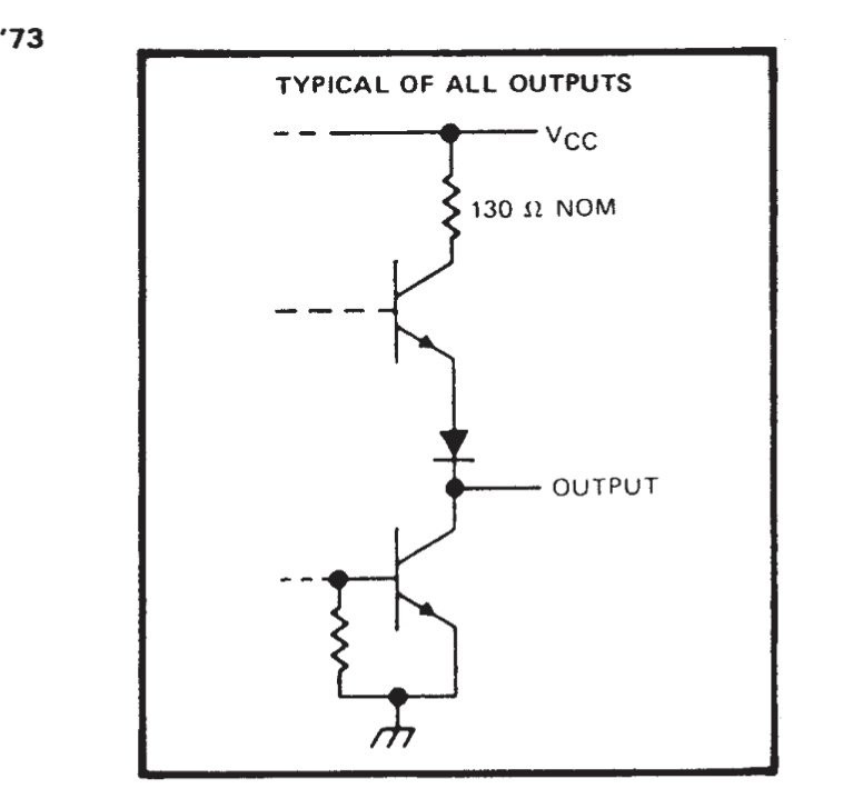
That resistor up there is what allows the output and the LEDs to survive. That, and the forward voltage of the LEDs.
The LEDs have a forward voltage of about 2V. Taking the 7V battery voltage, subtracting the foward voltage of 2V, Ohm's law says there'll be 38 milliamperes through the 130 ohm resistor in the IC.
The datasheet further notes that a "high" output will usually be lower than the supply voltage of the IC. That, of course, reduces the output current.
The LEDs get a final bit of help in that they are pulsed. They light up in alternation, each one only lit for half of the time. They have less time to heat up, so are less likely to fail - even in the unlikely case that they do get a really high current.
Discussions
Become a Hackaday.io Member
Create an account to leave a comment. Already have an account? Log In.