 Akshay Jain
How Does a PIR Sensor Work?
A PIR sensor detects the infrared radiation (heat energy) emitted by objects in its surroundings. It doesn’t emit any radiation of its own; instead, it senses variations in IR levels.
Since every object above absolute zero (-273°C) emits infrared radiation, the human body also radiates heat, which the PIR sensor can detect. By measuring these variations, the sensor determines whether motion is present.
Key Components of a PIR Sensor
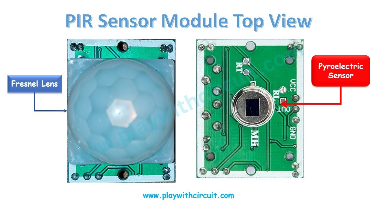
1. Pyroelectric Sensor
At the core of a PIR sensor is the pyroelectric material (such as a crystal) that responds to changes in infrared radiation.
-
When a person or object moves, the change in IR levels causes the material to generate a small electric charge.
-
The sensor converts this into a voltage signal that can trigger an alarm or output.
The pyroelectric element has two sensing slots. Each slot detects IR independently — one gives a positive output and the other a negative output. Under stable conditions, the slots detect equal IR levels, and the output remains zero.
When motion occurs (e.g., a human passes by), one slot receives more IR than the other. This differential change generates a detectable voltage signal, indicating motion.
2. Fresnel Lens
The Fresnel lens is a lightweight optical lens made of concentric grooves. It focuses infrared radiation onto the pyroelectric sensor, extending the detection range and creating a wider field of view.
This design makes the HC-SR501 capable of detecting motion across a broad area rather than just directly in front of it.
HC-SR501 PIR Sensor Module Pinout
The HC-SR501 PIR motion sensor has three pins:
VCC – Power supply (4.5V to 12V, typically connected to 5V).
GND – Ground (0V reference).
OUT – Digital output pin. This pin goes HIGH (3.3V/5V) when motion is detected and remains LOW (0V) when no motion is present.
Arduino Code
/*
How to Interface HC-SR501 PIR Sensor with Arduino
by www.playwithcircuit.com
*/
#include <LiquidCrystal.h> // We are using JHD 16x2 alphanumeric LCD using HD44780 controller for its controller
LiquidCrystal lcd(12, 11, 6,7,8,9);
int sensorInput = 2;   // Output for PIR sensor input for controller
int sersorReturn=0;
void setup() {
  pinMode(sensorInput, INPUT);   // declare sensor pin as input pin
  // set up the LCD's number of columns and rows:
  lcd.begin(16, 2);
  // set the cursor to (column = 0,row = 0)
  lcd.setCursor(0, 0);
  lcd.print("PIR Sensor Says:");
  // set the cursor to (column = 0,row = 1)
  lcd.setCursor(0, 1);
}
void loop() {
  sersorReturn = digitalRead(sensorInput);  // read input value

  if(sersorReturn == HIGH)
  {
    // set the cursor to (column = 0,row = 1)
    lcd.setCursor(0, 1);
    lcd.print("Motion Occurs");
  }
  else
  {
    // set the cursor to (column = 0,row = 1)
    lcd.setCursor(0, 1);
    lcd.print("Motion Stops ");
  }
}
Project Video
To learn more checkout: How HC-SR501 PIR Sensor Works & How to Interface it with Arduino
 Lithium ION
 hIOTron
 Tony Kambourakis