-
Testing
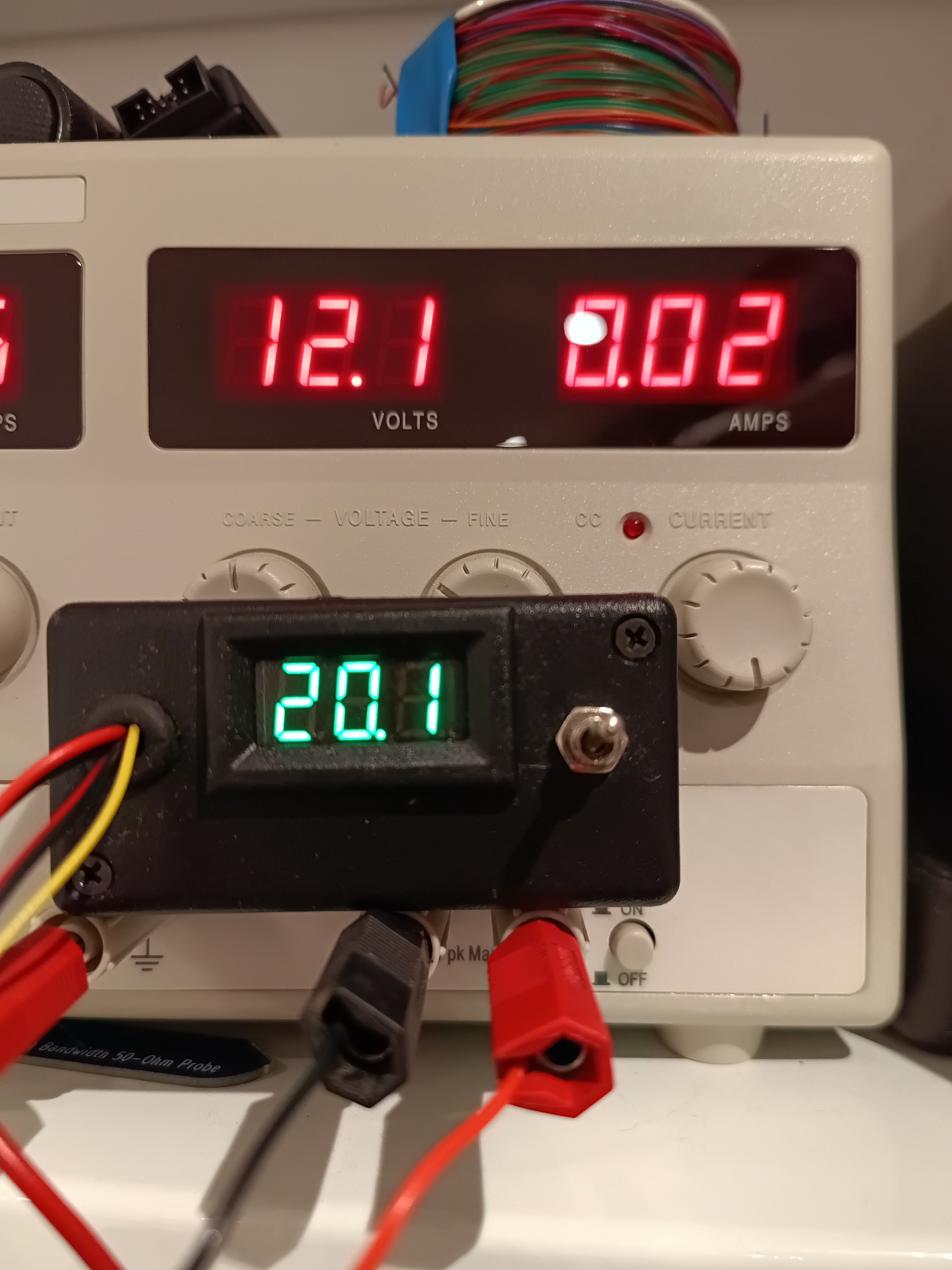
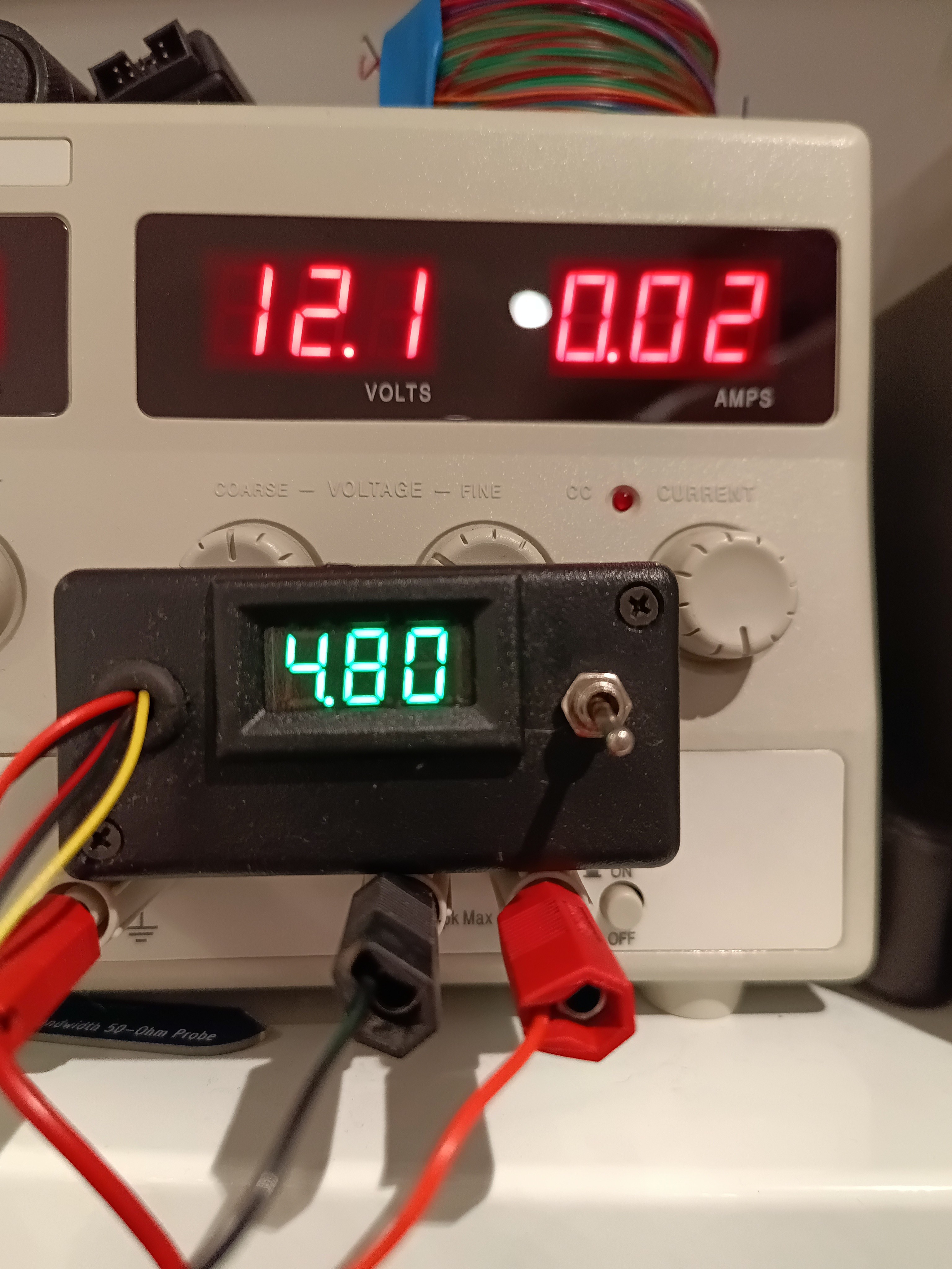
09/21/2025 at 13:30 • 0 commentsI've installed the DCDC in a plastic box with a little voltmeter that can be switched from -5V to 0V and -5V to +15V so if all is good it shows either around 5V or 20V.
![]()
![]()
I've put a 560R resistor from -5V to +15V. The meter now reads 14.5V so output power is around 0.38W but input is 0.73W so it's only 52% efficient. Not going to win any prizes I'm afraid.
![]()
-
Circuit details
09/21/2025 at 13:17 • 0 commentsThe inspiration for the project was partially from a frustration at having to purchase pricey Recom or Murata power supplies for gate driver power supplies and being given a Fair-Rite HF Mini Power kit with 80 material cores in it. 80 Material ferrite is usable up to a few MHz so I thought that this was an opportunity to make my own high frequency supply.
The design is fairly simple. There's a 1MHz oscillator that is fed directly into a dual gate driver which has inverting and non inverting outputs. The gate driver is being used as an H-bridge. The transformer is directly across the outputs with a DC blocking capacitor to prevent flux walk saturating the transformer.
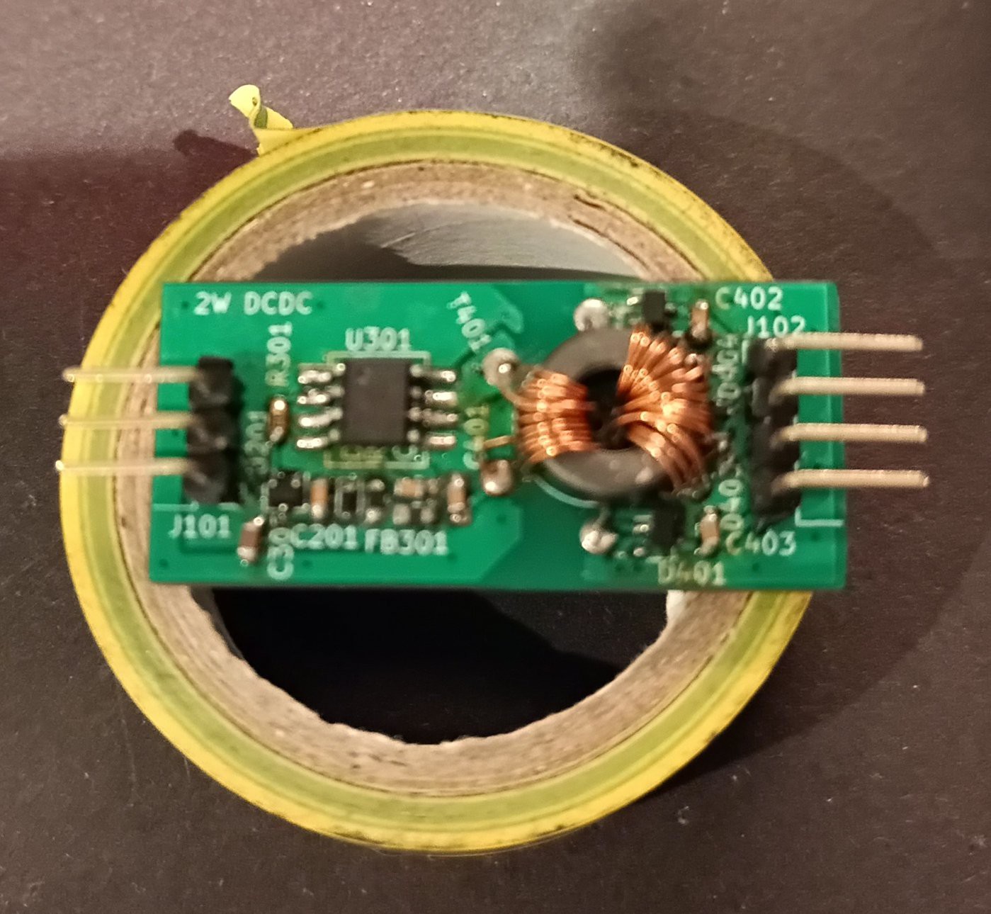
My camera isn't good enough to give a good photo but the transformer has well separated input and output windings to minimize capacitance between input and output. There's around 12 windings on the primary and 16 and 6 on the secondary to give around 15V and -5V from a 12V input.
[dcdc mounted on a roll of electrical tape for scale]
![]()
The output rectifiers are just BAT54S as the current isn't high but low reverse recovery and forward voltage is necessary. There are zener diodes to limit the output voltage. Output voltage can easily be changed by changing the windings on the output and the zener diodes.
It only gives around 0.4W which is sufficient for a low of applications but it's a bit below my target.My Peak LCR45 (after probe compensation) measures approximately 3pF input to output so the low capacitance target has been met. I was hoping for <10pF.
Isolated Gate driver supply
Design and build of a low capacitance isolated gate driver supply for SiC FETs.