Close
0%
0%

BeanBoard

QWERkY Keyboard and simple LCD display for BeanZee Z80 CPU board

Similar projects worth following
QWERTY Keyboard, simple LCD display and GPIO for BeanZee Z80 development board - the two boards together from a simple 8-bit computer for experimentation.

Keyboard

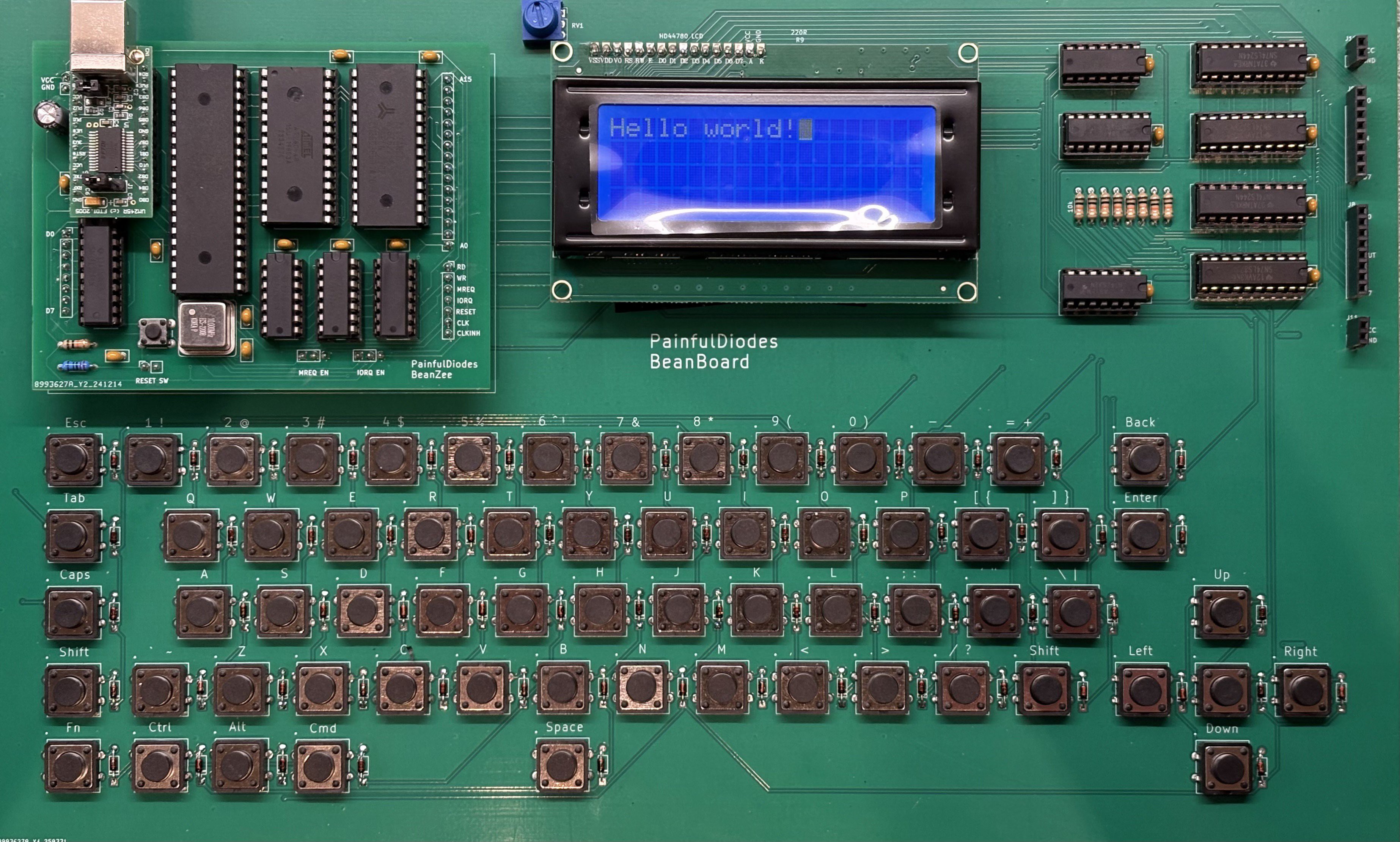
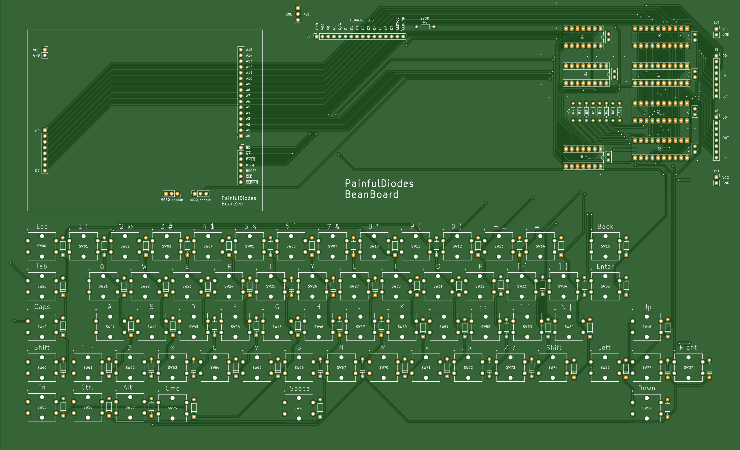
Aiming for the simplest possible design, using a matrix of switches.

Diodes are used with each switch to prevent ghosting.

The circuit expects the CPU to send a "strobe" to a keyboard output port. A latch is used to capture the strobe - so that the state persists after the CPU has stopped outputting to the port. This strobe should have only one bit set high. This is the "live" row.

Then the CPU will read from a keyboard input port to sense which columns are high - columns will be activated by switches being pressed. A buffer is used to gate the columns onto the data bus.

The CPU will loop back and successively set each strobe bit high. Having gone through each bit and then read back the columns, we will have 64 bits of data (8x8) representing which keys are being pressed.

The 8 electronic rows are arranged as 4 physical rows, pairing electronic rows consecutively: 0+1, 2+3, 4+5, 6+7
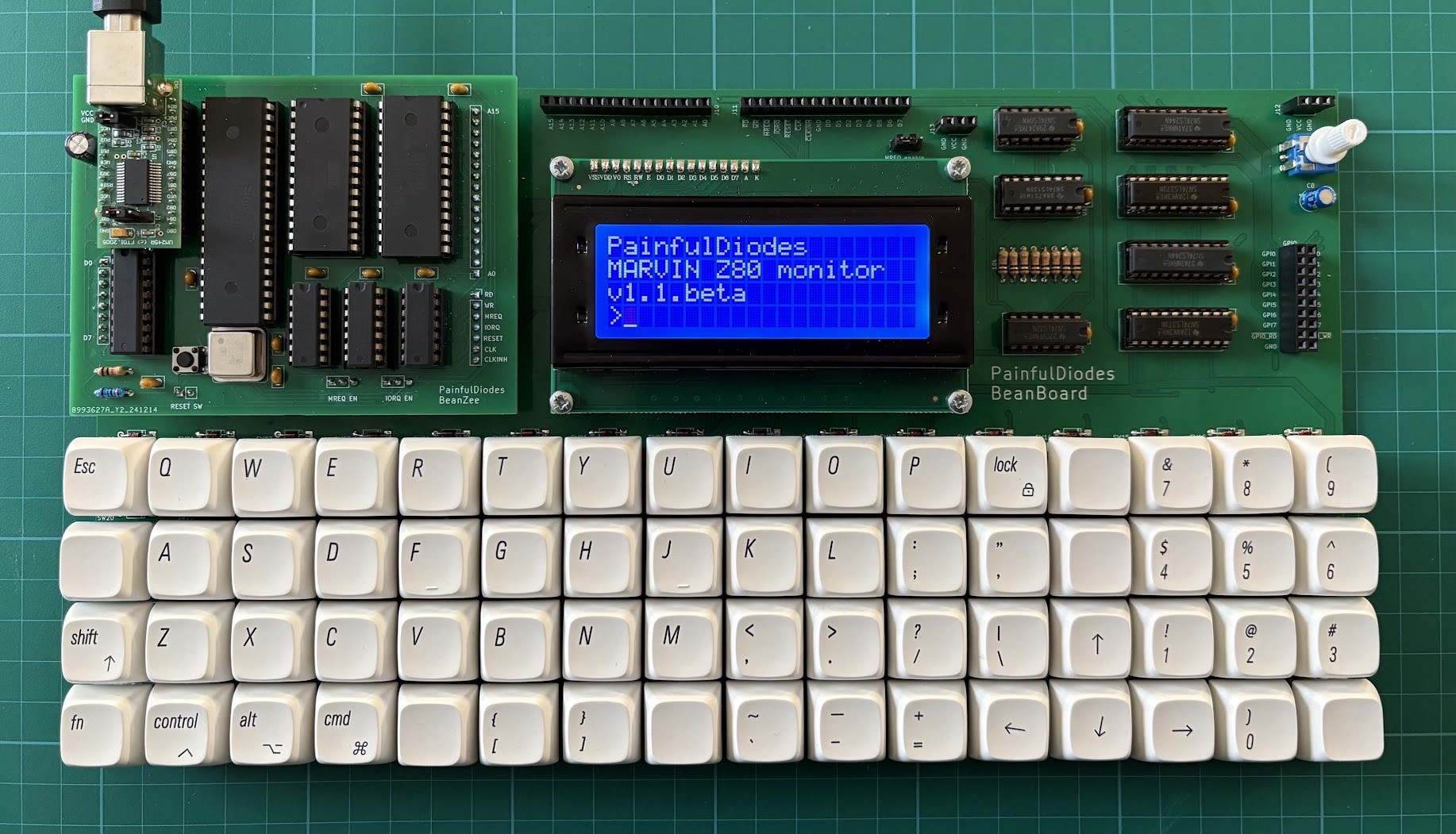
LCD

The Hitachi HD44780 LCD controller has been around since the 1980's and is still popular to control character-based LCD displays:

A parallel interface makes it CPU bus friendly - with 8 data bits, enable, R/W and register select inputs.

GPIO

Repeating the keyboard logic allows for 8 general purpose binary outputs and inputs which can be used for experimentation.

Port address decoding

A 3 to 8 decoder has been used to select pairs of ports. A0 is then used to chose between ports in a pair. The BeanZee board has the logic to separate ports based on A0, and there's a similar arrangement here for LCD. The keyboard ignores A0.

KBD_PORT equ 2 ; or 3
LCD_CTRL equ 4 ; LCD control port
LCD_DATA equ 5 ; LCD data port
GPIO equ 6 ; or 7

Z80 bus

The BeanZee Z80 bus is extended on a BeanBoard connector to allow for expansion. Note that the MREQ_enable jumper is also extended to allow the memory select logic to be changed.

  • TFT panel for Z80 homebrew via bit-banged SPI

    Stephen Willcock10/24/2025 at 12:35 0 comments

    This took a bit of effort but was very worthwhile! While pondering designing a VGA add-on for my BeanBoard I stumbled over parallel-RGB interfaces for TFT panels, and found Adafruit have a nice little controller board with an SPI interface. As I already have a GPIO on my board, I just had to figure out how to bit-bang SPI and then interact with the RA8875 chip

    More details here: https://painfuldiodes.wordpress.com/2025/10/24/tft-display-for-z80-homebrew/

  • Monitor program BeanBoard update

    Stephen Willcock09/26/2025 at 18:22 0 comments

    I’ve put some time into getting my BeanZee monitor program (Marvin) to use the BeanBoard keyboard and LCD as a console device. It is working well!

    https://github.com/PainfulDiodes/marvin/releases/tag/v1.2.1a

  • BeanBoard v1

    Stephen Willcock09/26/2025 at 17:58 0 comments

    Having spent a little time playing with the BeanBoard prototype, I have now produced a new version to fix most of the the things that were bothering me. Although I was toying with the idea of shrinking the board as small as possible, using tactile switches, in the end I couldn't resist a mechanical keyboard. The layout is a bit quirky, but I like it.

    The PCB is more compact than the prototype and I also added a bus connector for further expansion.

    More details on GitHub:

    https://github.com/PainfulDiodes/BeanBoard

    (6th June 2025)

  • Prototype

    Stephen Willcock09/26/2025 at 17:50 0 comments

    I’ve now assembled the BeanBoard prototype. I’m generally happy - managed to load and run some test programs showing things are working as expected. However there are some significant issues… on reflection the buttons need to either be small tactile or Cherry-MX-syle keyboard switches, the large tactile buttons seem just wrong, the board is way too large. 

    I do need to shrink the whole thing, and maybe move the logic underneath the BeanZee piggyback board, and also decide whether to have a proper MX keyboard, or a tiny "single finger typing" board. The LCD may need to be angled to read easily, but this too may be solved just by making the board smaller. But the biggest problem was that I bungled the switches on the layout. On the schematic I used a generic switch and then later added a specific button footprint. Problem was I should have replaced the switches on the schematic, which would have made the pinouts explicit. As it was, all the switches were shorted because the pin designations were wrong. Removing the diodes and patching with links to correct the wiring works, but is a real pain. Lesson learned.

    (8th April 2025)

  • PCB design

    Stephen Willcock09/25/2025 at 07:45 0 comments

    Having proven the LCD display and QWERTY keyboard design on breadboard, I have designed a PCB in KiCAD and have now sent off an order to JLCPCB. As planned, the BeanZee Z80 homebrew, and an LCD module will plug into this new PCB, forming a small self-contained computer.

    I have some misgivings about the choice of buttons. Originally I was looking at using small tactile buttons, but was worried they would be too fiddly for my large digits.

    I've gone for larger tactile buttons, which has made the PCB quite large (327 mm x 199 mm). Given the size of the PCB, I could switched to Cherry MX keyboard buttons, but these would have pushed the overall price up. I have compromised and stuck with the tactile buttons. We shall see!

    (29 March 2025)

View all 5 project logs

Enjoy this project?

Share

Discussions

Does this project spark your interest?

Become a member to follow this project and never miss any updates