I am currently working toward my airframe & powerplant certification, and as such, I wanted to make a useful project that would improve my airframe skills, improve my ability to produce airworthy rivets, all while making an end product that was both useful and visually appealing.
I decided on making a simple toolbox. Using 0.040" 2024 T3 Alclad alumminum plate and AN470 2117 T3 solid universal head rivets, some basic hardware store grade catches and a handle, I produced the simple aluminum toolbox.

Now, of course, I didn't just grab some metal, makes some bends and start throwing the toolbox together.
The Design Phase - The Math
I started off with some very rough design parameters. The toolbox was to be approximately 18" wide, 7" deep and 6" tall. These are known as the mold lines of the project, from which I found my setbacks, bend allowances and leg lengths.
To calculate the layout, I started with the mold dimensions, which are the exterior dimension of the toolbox, or really any project you wish to layout.
I then calculated my setback and bend allowances, which are as follows.
For 90 degree bends
Setback is calculated using the formula
SB=T+R
SB = K(T+R) where K is your K-factor, T is the thickness of your material and R is the radius of your bend, which is also the radius of your brake. Because the K-Factor for a 90 degree bend is 1, we can simply the formula to be SB=T+R,
Bend allowance is calculated using the formula
BA =(2π (R + 1/2 T)) /4
BA =(2π (R + 1/2 T)) /4 where T is the thickness of your material and R is the radius of your bend, which is also the radius of your brake.
Once you know the setbacks and bend allowances, you can calculate your leg distances for layout.
On a piece of sheetmetal that you are making a single 90 degree bend, you would calculate the distance of the legs by taking the first leg of the bend and subtracting a setback, then measure your bend allowance distance and then add the second leg distance minus another setback.
For bends other than 90 degrees
To calculate bends which are other than 90 degrees, you need to know the K-Factor. You can either calculate the K-Factor or you can use a K-Factor Chart
Once you know the K-Factor, you can calculate your setbacks and bend allowances. It is important to remember that you need to calculate setback and bend allowance for EVERY angle you bend and to make sure to use the correct values for the correct angles when doing your layout.
To calculate setback for bends other than 90 degrees
SB=K(T+R)
SB = K(T+R) where K is your K-factor, T is the thickness of your material and R is the radius of your bend, which is also the radius of your brake.
To calculate bend allowance for bends other than 90 degrees
BA = (0.01743R + 0.0078T)N
Bend allowance = (0.01743R + 0.0078T)N where R is the radius of the bend, T is the thickness of the metal and N is the number of degrees in the bend which you wish to make.
On a piece of sheetmetal that you are making a single bend, you would calculate the distance of the legs by taking the first leg of the bend and subtracting a setback, then measure your bend allowance distance and then add the second leg distance minus another setback.
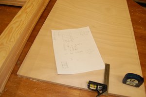
Once you have your layout, much like you see here. For reference, the toolbox's mold lines are 18" x 7" with a 4" front and a 5" back. Using a 1/8" radius brake, my bend allowance for .040" alclad is 0.2280"
Now the easiest thing to do is take a micrometer and a sharpie and begin laying out everything on a piece of sheetmetal. Make all of your cuts and relief holes first and then you are ready to start bending everything up.
To layout your bends as they will be positioned in the brake, measure the distance of the radius of the bend, in my case, 1/8" or 0.125" from the intersection of the leg line / bend allowance line which is sitting under the brake. This measurement is your sight line, which you will align to the front of the brake edge. You should just see your sight line and it should...
Read more » BreeStephany


 Geoff Nicholson

 Bharbour
 David Matthew Mooney
Nice Job!