 Jithin Sanal
Introduction
In this tutorial, we’ll build a home-automation controller using a Raspberry Pi Zero W, two MOSFET switches, and a minimal Flask web console.
By the end, you’ll be able to toggle devices ON/OFF from your phone or laptop over Wi-Fi. We’ll keep the circuit clean, the power safe, and the code simple so you can customize it later.
Components You’ll Need
- Raspberry Pi Zero W (40-pin header soldered)
- 12 V DC adapter for your loads
- 2 × logic-level N-MOSFETs (e.g., AO3400A, IRLZ44N, FQP30N06L)
- 2 × flyback diodes (1N4007/SS14) for inductive loads (relays, solenoids, motors)
- Gate resistors: 100–330 Ω (one per MOSFET)
- Gate pulldowns: 100 kΩ (one per MOSFET)
- 5 V supply for the Pi: USB 5 V or TSR 1-2450 switching regulator (drop-in 7805 replacement)
- Wires, screw terminals, your 12 V devices (lamp, pump, lock, fan, etc.)
Why Raspberry Pi Zero W
- Tiny, affordable, and has built-in Wi-Fi
- Runs Python + Flask easily for a web UI
- Perfect for small automations without cloud complexity
Video Tutorial
Want a fully functional smart home system without the high cost? This is the ultimate DIY Home Automation project using the tiny, ultra-cheap Raspberry Pi Zero W!
Circuit
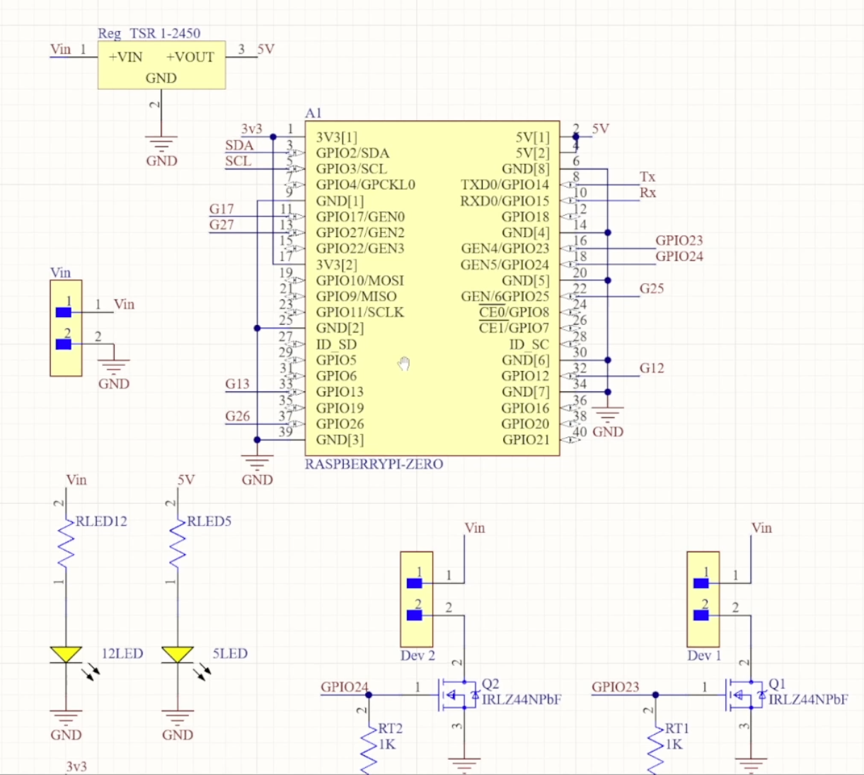
Circuit – Full Explanation
The circuit is simple and reliable. We use two low-side N-MOSFET switches controlled by the Pi’s GPIO pins.
- Each device connects from +12 V → Device → MOSFET Drain.
- The MOSFET Source goes to Ground.
- The MOSFET Gate is driven by a Pi GPIO pin through a 100–330 Ω resistor.
- A 100 kΩ pulldown from Gate to Ground keeps the MOSFET OFF at boot.
- For inductive loads (relay/solenoid/motor), add a flyback diode across the device: cathode to +12 V, anode to the device/MOSFET side.
- Common ground is mandatory: connect Pi GND to the 12 V supply negative so the gate signal has the right reference.
When the gate goes LOW, the device turns OFF.
Pin Map (BCM → Physical Header Pin)
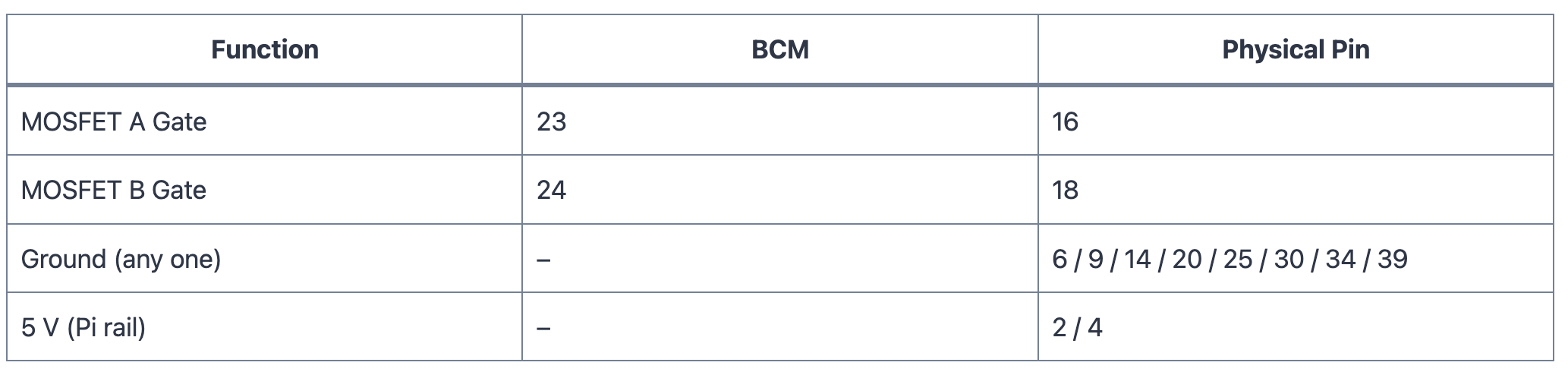
We use BCM numbering in the code. The physical positions help if you wire from a loose Pi.
Power
We have two rails:
- 12 V for the devices
- 5 V for the Raspberry Pi
- A good 5 V USB supply into the Pi, or
- A switching regulator like TSR 1-2450 stepping 12 V down to 5 V.
If you might use USB and the 5 V regulator at the same time, isolate them—add a series Schottky diode from the regulator to the Pi 5 V rail (or use an ideal-diode/power-mux IC) to prevent back-feeding.
Voltage Regulator
The TSR 1-2450 is a drop-in switching replacement for 7805. It delivers a cool, efficient 5 V up to 1 A from 9–12 V input.
Place a 10–22 µF capacitor near VIN and a 22–47 µF capacitor near the 5 V output for stability during Wi-Fi spikes.
If you plan heavy 5 V USB devices, consider a 1.5–2 A regulator.
GPIO Voltage
Pi GPIO is 3.3 V logic. Pick MOSFETs that turn fully ON at Vgs ≈ 3.3 V with low Rds(on) (e.g., AO3400A, IRLZ44N, FQP30N06L).
Always include the gate series resistor and the 100 kΩ pulldown for clean, predictable switching.
Advantage of Using a PCB
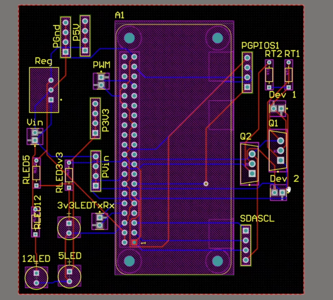
A PCB gives you:
- Neat screw terminals and proper footprints
- Clean labeling and consistent wiring
- Space for fuses/TVS/protection
- A robust build that fits in an enclosure
Prototype on a breadboard first, then move the same netlist to PCB for reliability.
Setting up the Pi
- Flash Raspberry Pi OS (Bookworm), boot, connect Wi-Fi
- Enable SSH if needed
- For a full imaging/first-boot guide, see my earlier video where everything is shown step-by-step
Initial Testing of GPIO Pins (Simple Code)
Before the web UI, test that GPIO 23 and 24 switch correctly
File: simple_on_off_test.py
# simple_on_off_test.py
import time
import RPi.GPIO as GPIO

GPIO.setmode(GPIO.BCM)
GPIO.setup(23, GPIO.OUT, initial=GPIO.LOW)
GPIO.setup(24, GPIO.OUT, initial=GPIO.LOW)

# Turn ON GPIO 23 for 2s
GPIO.output(23, GPIO.HIGH)
time.sleep(2)
GPIO.output(23,...
Read more »
 lalalandrus
 Arkadi
 joshua.vader
 Filip Mulier