Hello everyone! Welcome to the first proper hardware log for the `stray` project.
My goal here is to walk you through the v1 prototype hardware: why we chose certain parts, how it's all connected, and (most importantly) all the "features" and quirks you'll find if you dig into the design files.
Design Philosophy
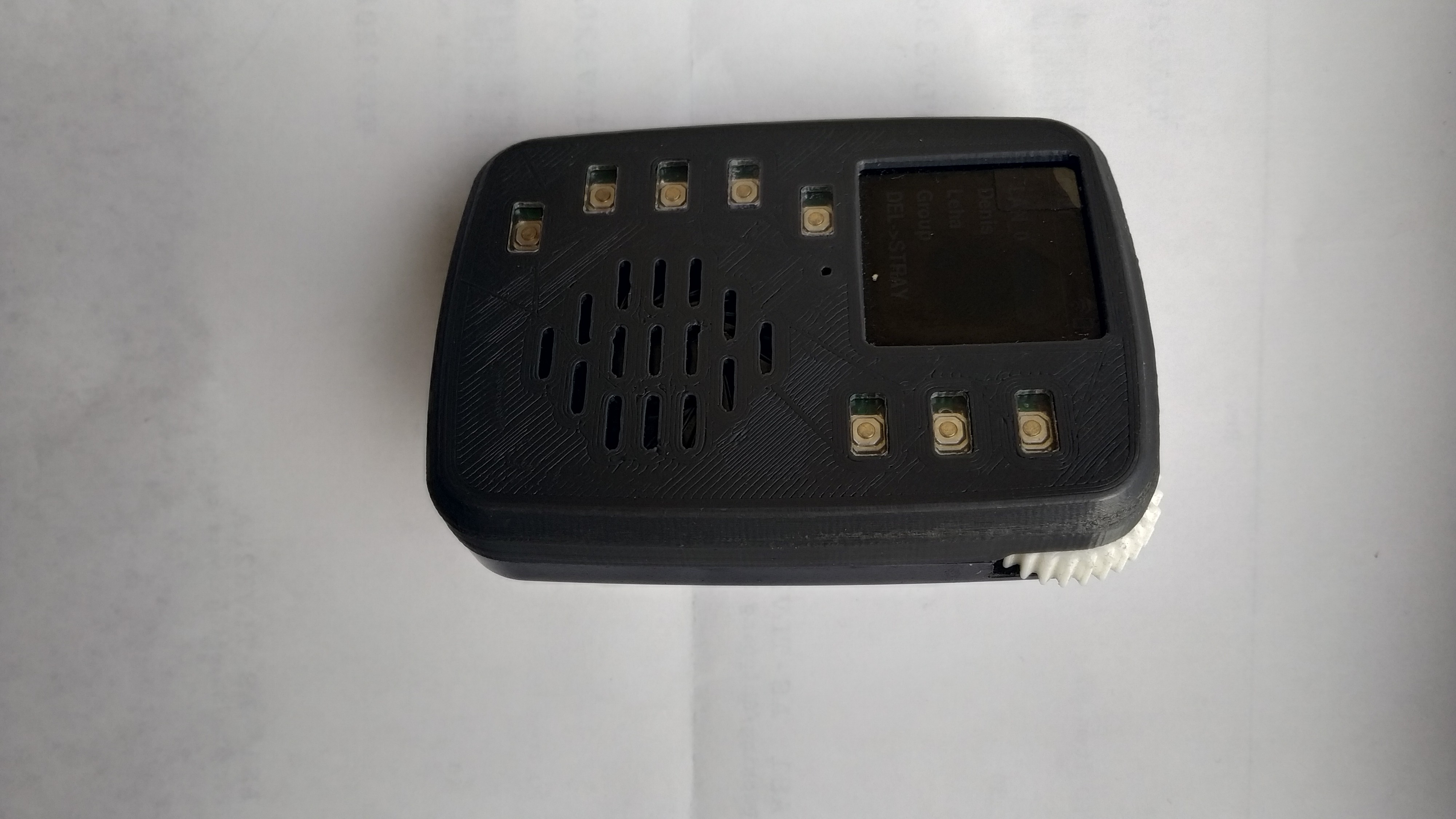
The main driver for this design was ergonomics. We wanted a device that felt comfortable to hold, with all the main functions "at your fingertips." This led to some... interesting design choices.
Core Components
Here’s a quick rundown of what's on the board:
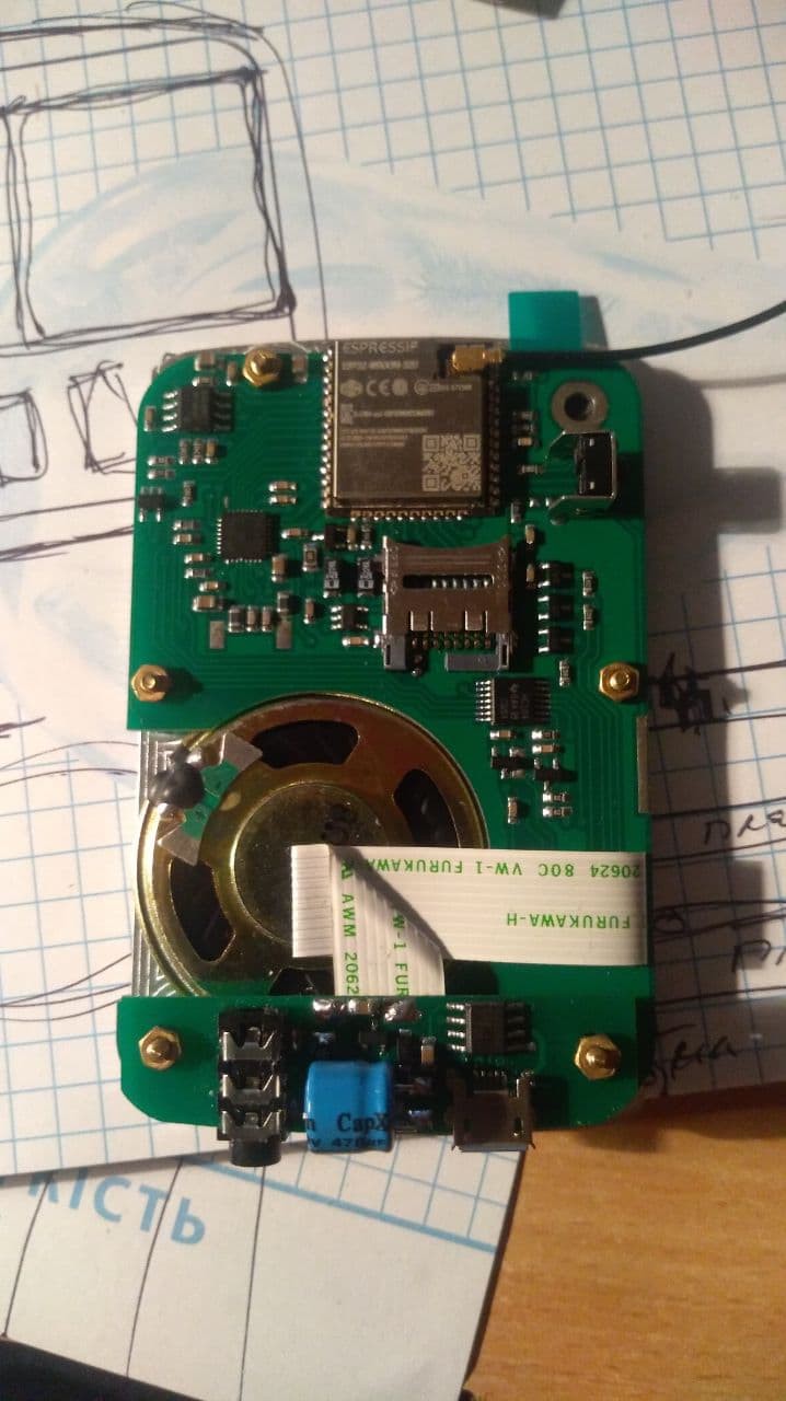
- MCU: An ESP32-WROOM module, using an external IPX connector for the antenna.
- Encoder: An AS5601 magnetic encoder. It’s super smooth. We're currently using I2C to read its position, but the A/B pins are also routed if you prefer that approach.
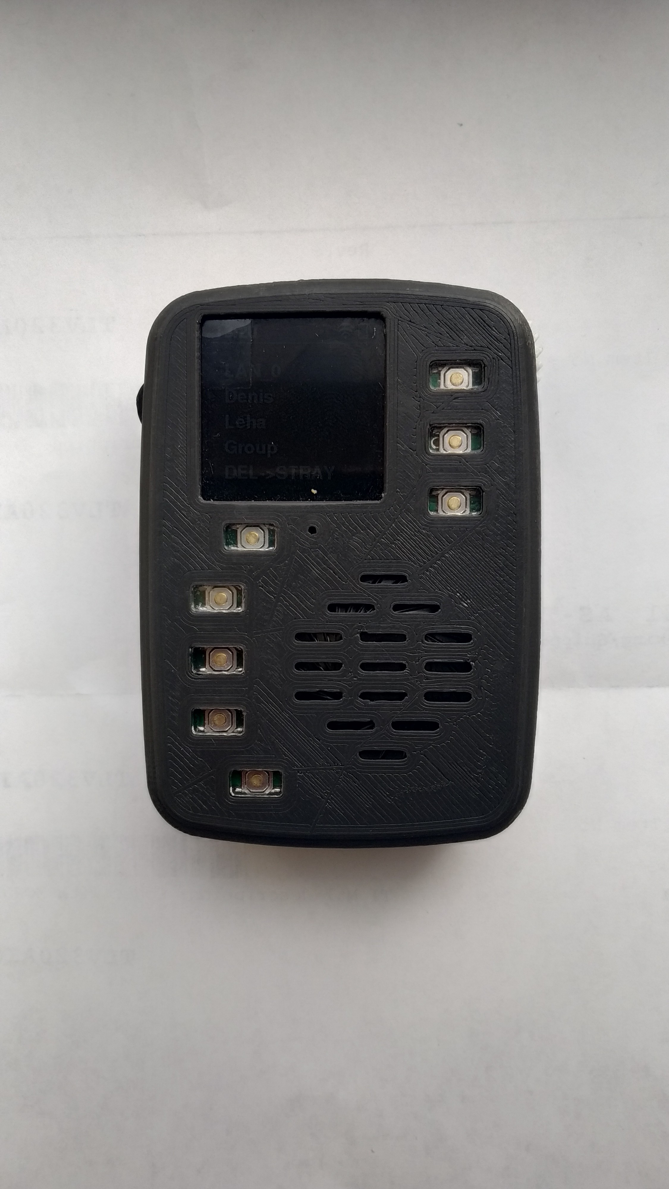
- Display: A 1.54" 240x240 LCD** based on the ST7789 driver. It's connected via SPI, with a PWM pin for backlight control.
- Audio Codec: This is the big one. We're using a TLV320AIC3120IRHBR Low-Power Mono Codec. It has an embedded miniDSP and a Class-D speaker amp. It's total overkill, but it was part of the original design.
- It's controlled via I2C and streams audio data via I2S.
- It's connected to a POM-3046P-R microphone and a small speaker.
- Buttons (Simple): There are two dedicated buttons: a side-mounted PTT and a bottom-mounted Power button.
- Buttons (Complex): We have dedicated PTT button on the sidde and a PWR button, last in row (bottom left)
- The other 7 buttons are all connected to a **74HC164PW 8-bit shift register**. By clocking a single pin, we get a key code back at the input. This scheme is... a bit convoluted. It's not great at detecting multiple key presses, so I simply avoid those scenarios in the software.
- Charging: A MAX1811 chip handles the Li-Ion battery charging.
- Battery: We managed to fit a 4000mAh battery, which was the limit for the case. We haven't done formal battery life tests, but it doesn't give you that "must always be charging" feeling.
- Unused Parts: There's an audio jack wired to the codec, but I just never got around to implementing it in the software. And a microSD card holder which, I was told wouldn't work, so I didn't bother to even try to start.
---
Here's how it looks inside
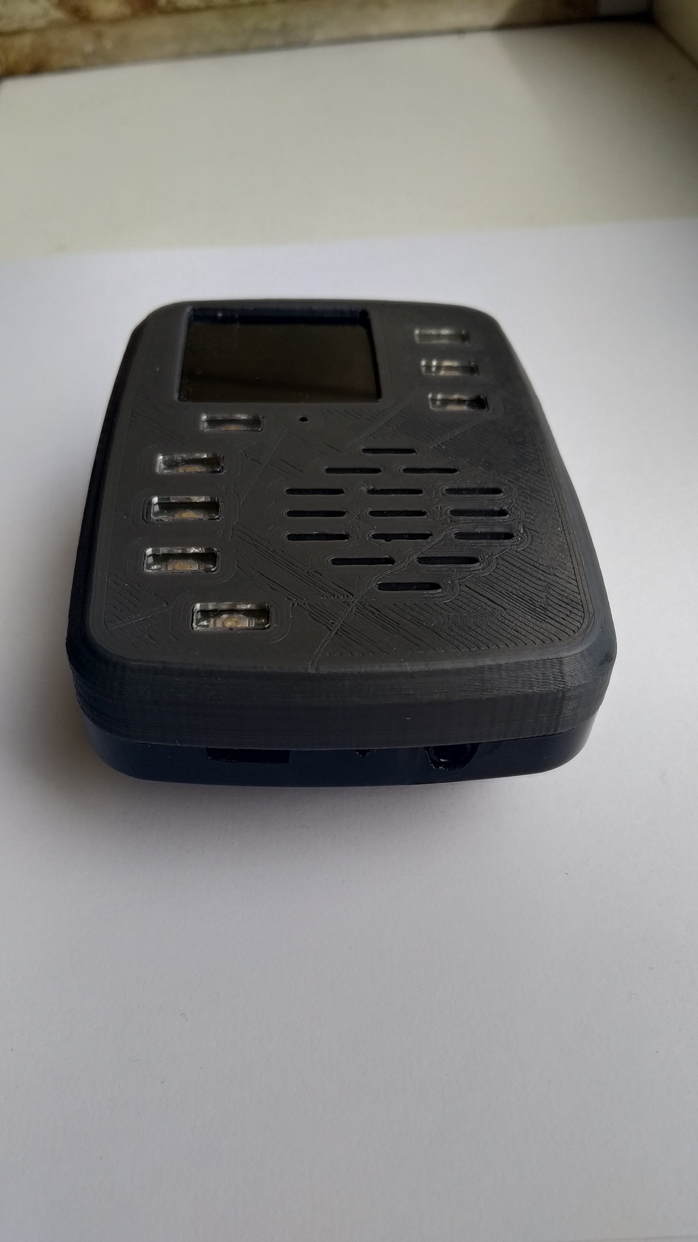
The Enclosure (A "Hybrid" Approach)
The case is a 2-part custom assembly:
- The back panel is a heavily modified ("filed-down") off-the-shelf plastic enclosure.
- The front panel is 3D printed, and we also had a variant with a laser-cut metal plate.
- The PTT button-lever and the encoder wheel are also 3D printed, but I'm afraid the STL files for these small parts have been lost to time.
- Inside, the (two) boards are stacked and mounted using standoffs.
---
"Features, Not Bugs" (The Quirks)
This is the fun part. This board has character.
- Quirk #1: Flashing is... special. The microUSB port is for charging and flashing firmware if you manage to make custom cable connecting external USB-to-UART converters Tx/Rx with microUSB's D+/D-.
- Quirk #2: Boot Mode.** To put the ESP32 into bootloader mode, you have to **hold one of the 7 keypad buttons** *while* pressing the Power button. I don't remember the exact schematic magic, but it's tied to the boot pin.
- Quirk #3: Battery "Monitoring". It's primitive. We just do a direct ADC read on the battery voltage. The "percentage" you see in the UI is more of a guess than a precise measurement.
- Quirk #4: The Dead SD Card Slot.** Yes, there's an SD card slot on the board. No, it doesn't work. We messed up the pins. :)
- The BIG One (My "Favorite" Bug): The output from the 7-button shift register is wired to IO_0. If you know the ESP32, you might know that the standard I2S driver *also* tries to claim IO_0 for its use by default (even though it doesn't strictly need it).
- This led to a *maddening* bug where the keyboard worked perfectly... right up until the codec initialized, at which point the keyboard would go completely dead.
- Honestly, this bug is what pushed me to rewrite the entire codebase from scratch. I'm actually happy about it now, because the new architecture is so much better.
---
Hardware <-> Software Integration (The BSP Layer)
To make this (and any future) hardware manageable, I created a Board Support Package (BSP) layer. The idea is to separate the physical pinouts from the main application logic.
All the init code, pin definitions, and low-level hardware functions are in one place. If we (or you) make a `rev2` board, you'd just create a `bsp_rev2.c` file with the new pin map, and the main code wouldn't have to change.
These are the key functions the main app uses from the BSP:
- `bsp_rev1_init()`: Initializes all hardware.
- `bsp_rev1_power_latch_off()`: Turns the device off.
- `bsp_rev1_get_display_config()`: Returns the SPI config struct for the display.
- `bsp_rev1_get_i2c_config()`: Returns the I2C config struct.
- `bsp_rev1_get_i2s_config()`: Returns the I2S config struct.
- `bsp_rev1_PTT_status()`: Polls the PTT button state.
- `bsp_rev1_POWER_status()`: Polls the Power button state.
- `bsp_rev1_keyboard_scan()`: Polls the shift-register keypad.
- `battery_monitor_get_voltage_mv()`: Reads the battery ADC.
Source Files & Final Notes
The PCB source files were created in DipTrace. It's a free-for-small-projects tool, but it's not very common, so you'll have to download it if you want to poke around.
Honest admission: The Bill of Materials (BOM) in the design file is probably incomplete. I don't have the mental energy to go back and fix that old design, just like I didn't want to maintain the old code. *However*, if you are serious about building this exact version, reach out, and I'll do my best to help.
All design files are now available on my GitHub.
I think that's everything! My next log post will dive into the software architecture.
I'd be happy to hear any feedback. See you in the next post!
Discussions
Become a Hackaday.io Member
Create an account to leave a comment. Already have an account? Log In.