 Mario Ninic
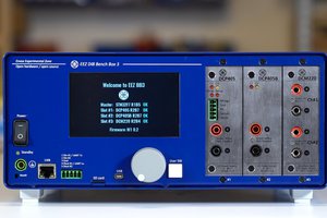
I purchased this power supply from Amazon and decided to take a look inside to see if it could be controlled by a computer. To my surprise, I found a serial port. After connecting a serial-to-TTL interface, I received a response. It took a bit of experimentation to determine that the communication protocol used was MODBUS over a serial bus.
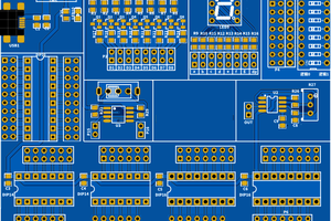
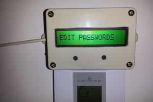
The device consists of two main modules: a power converter board and a processor board with an LCD display. These are connected via a small 8-pin header (only four pins are used), which also communicates via the MODBUS protocol.
The manufacturer appears to be Wuzhi:
http://qingdaowuzhi.com/
I attempted to contact them for register and bus protocol details without success. However, I later found a manual for another Wuzhi product — the ZK-10022C — that included a complete register description, which turned out to be almost fully compatible.
To connect to the power board, I used a USB-to-RS232 converter along with an RS232-to-TTL interface. The wiring connections are as follows:
GND  -----------  GND of RS232 module
TXD  -----------  RXD of RS232 module
RXD  -----------  TXD of RS232 module
+5V  -----------  VCC of RS232 module
The manufacturer’s manual also references a PC software tool called “Upper Computer”, which was helpful for debugging. It can be downloaded from the Wuzhi website as:
Wuzhi_Link_V1.0.11.exe
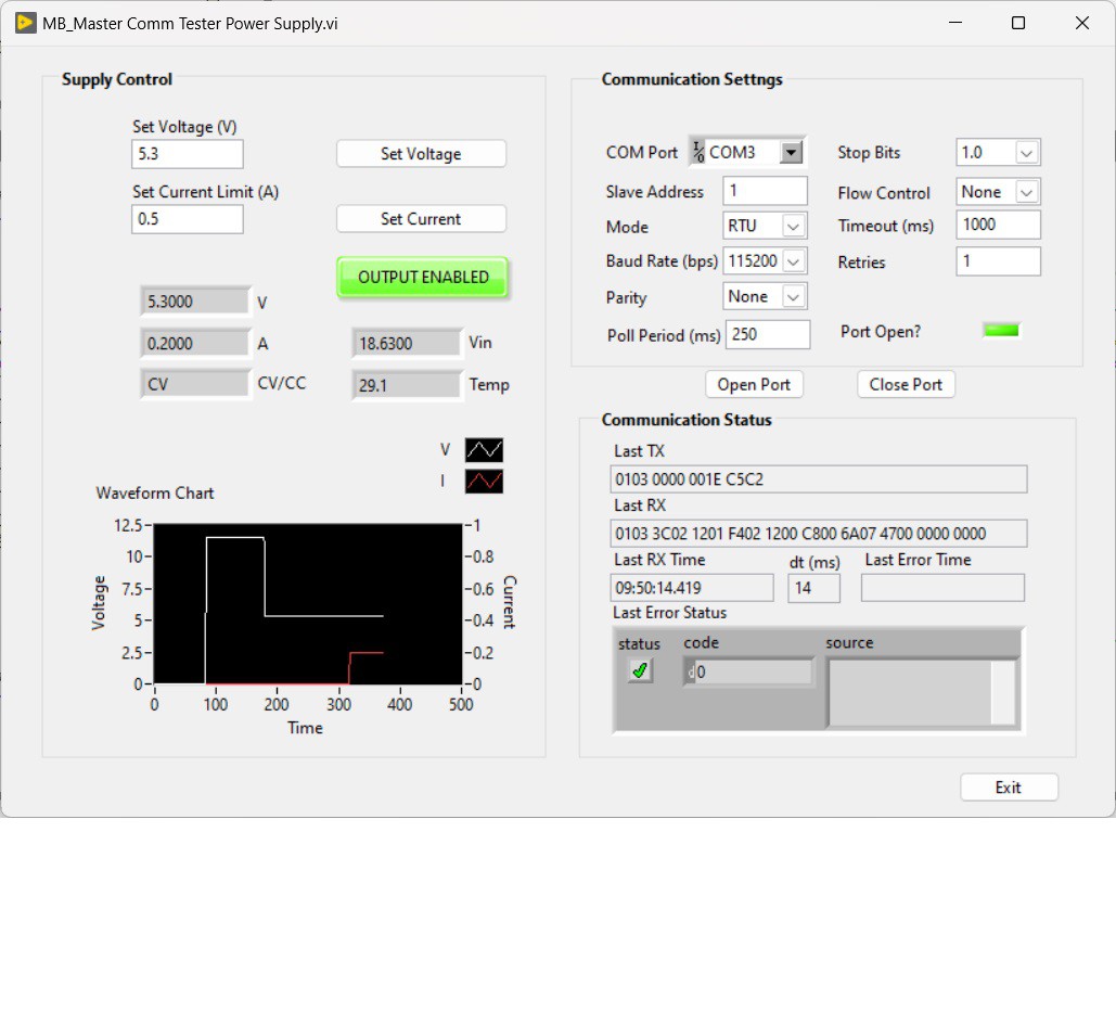
For my own testing, I used the LabVIEW MODBUS toolkit available on GitHub, created by Ryan Porter:
https://github.com/rfporter/Modbus-Master.git
I started with the MB_Master Comm Tester.vi example and modified it to suit my needs.
This module can be useful in projects that require computer-controlled voltage sources. My plan is to use it as part of a tube tester, in combination with a voltage booster described in Elektor magazine:
https://www.elektormagazine.com/magazine/elektor-201503/27579
 Denis
Denis
 Luke
Luke