Close
0%
0%

Fully Transparent Folded Cube Badge

ESC{21} conference badge made with clear PET and loaded with LEDs

Similar projects worth following
This is a fully transparent - except for the copper! - conference Badge designed for the Italian End Summer Camp con. It runs WLED with SoundReactive and a few more usermods on the ESP32-C3. Coming at 30x30x30 mm, it's really compact, and can easily fit on anyone's cluttered desk.

Please find all details inside the original GitHub repo.

Special thanks to Kezi, Kowalski, K3lite & Baobots for the efforts spent into debugging & flashing all the units during Camp.

And for going the extra mile and designing a custom case that solves many assembly issues, a very felt thank to k0bld.

The badge is higly experimental, it was designed as a very high risk blind shot at transparent flexible PCBs with dual-side assembly.

It turned out ok, but we did have some production issues, where the manufacturer baked a couple of panels too much, ending up all wrinkled - but still we managed to flash and use them!

Component Abuse Challenge 2025 entry summary:

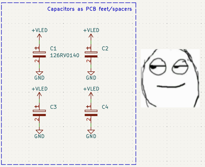
  • Capacitors used as feet, while still decoupling the LEDs

  • Resistors used as thickener for the Type-C connector

  • i2s line shared with MCU bootstrapping pins

The badge has:

  • An ESP32-C3 chip, the cheapest and smallest ESP with embedded flash.
  • The TDK ICS-43432 i2s digital microphone, as it was the only one available for assembly at the time, works great!
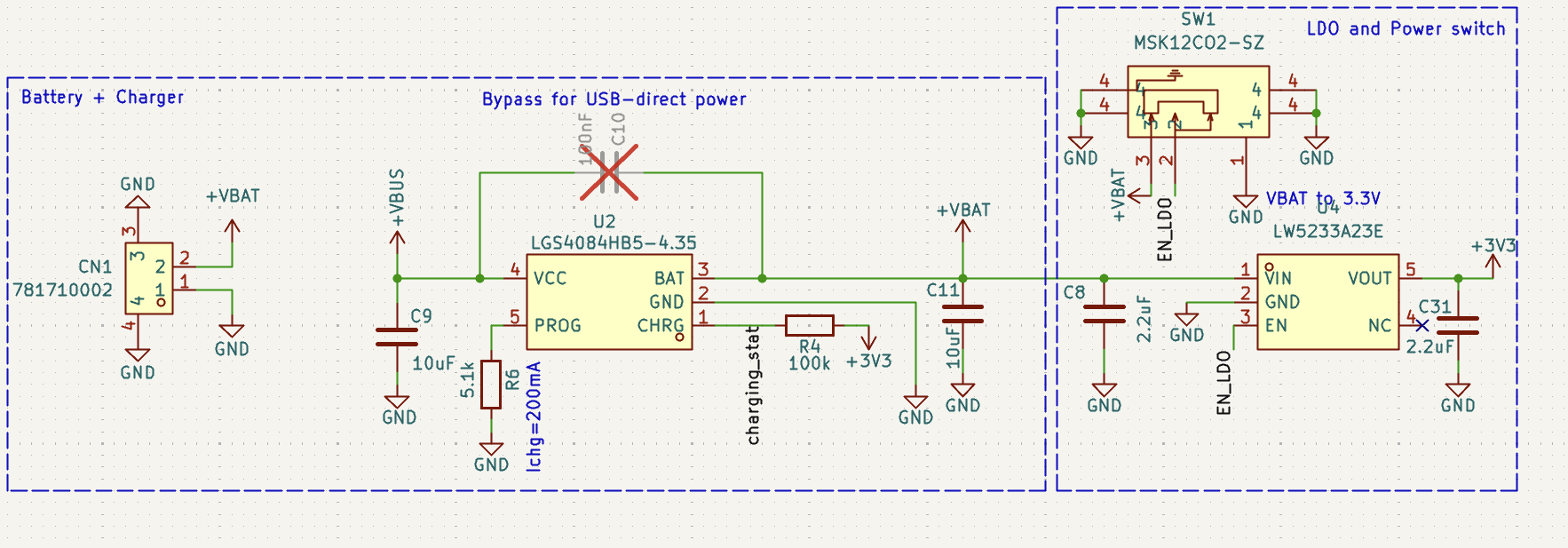
  • A 4.35V li-ion battery charger.
  • A custom made 4.35V, 500mAh battery with a Molex MXL connector, extremely energy dense 5.5(thick)x26x26mm shape.
  • 4 hours of battery life with SoundReactive effects.
  • Foldable, reversible, transparent, cool AF, flimsy USB Type-C flap acting as a male end.
  • 42(!!) addressable 1x1mm super tiny WS2812 LEDs. Actually there are 43, but one is wired in parallel as we used it to test dual side assembly for tiny pads.
  • The LEDs are powered straight from the battery, through an 87mOhm MOSFET, doubling efficiency compared to powering through the onboard LDO.
  • Tiny (I'm not joking) chip antenna blasting 50 meters of Bluetooth. Luckily were we live we don't have the FCC.
  • Battery voltage sensing that is enabled only when the LEDs are to avoid having any idle current discharging the battery on its own.

I've done some, somewhat clever trickery since I was out of gpios. As you can see, the strapping GPIO9 and the UART out GPIO20 are both connected to the i2s microphone. We were fairly sure this would work after looking at how i2s starts transactions. And in fact it did. 

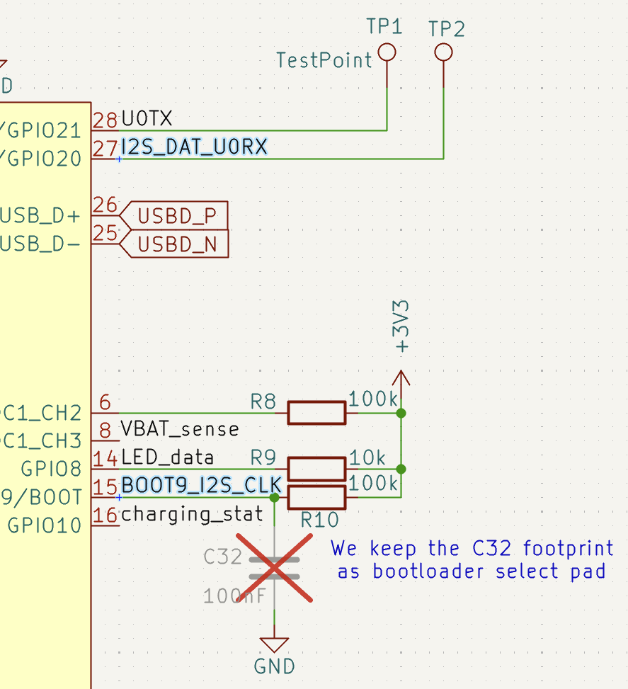
Can you tell I've had some fun designing the power path? You can see by yourself what it generally does, but essentially:

  • I didn't want the battery to wear down while charging, so it's limited to 200mA (0.4C).
  • I wanted the battery to be as isolated as possible once the power switch is flicked.
  • I wanted to be able to bypass the battery in case someone was looking to power it over USB only as desktop lamp. Why the hell would you have a desk lamp with an embedded battery?

I was trying to have dinner when something flashed in my brain. Capacitors. Are. Feet.


badge_short_video.mp4

Short video demonstrating the sound-related effects.

MPEG-4 Video - 13.11 MB - 10/28/2025 at 12:58

Download

  • 1 × Flexible PCB
  • 1 × Components
  • 1 × 500 mAh 4.35V Battery
  • 1 × UV-Glue

  • Escape the Shape

    jacopops10/28/2025 at 13:58 0 comments

    I started by designing the 3D shape of the iconinc "esc" keycap - from which the End Summer Camp borrows its logo.

    Then I went onto the metal sheets plugin on Fusion 360, allowing almost to "overmold" the initial shape.

    Finally, by "unwrapping" the sheet design you get the 2D dxf. 

    Once imported into Kicad, it looked liked this. I had to clean it here and there for some minor vectors, but had no major troubles with Kicad.

View project log

  • 1
    Initial Positioning

    Folding Instructions for the BadgESC{21} Badge

    These are the instructions for folding the BadgESC{21} Badge into its final cube shape. Use a plastic card or another thin, flat object to achieve tight bends on the PET plastic substrate. It may also be possible to mold the shape by gently warming the material, although this method has not been tested.

    To secure the folded parts, use UV glue, superglue, or another strong adhesive.

    Step 1: Initial Positioning

    1. Place the badge on a flat surface with the components facing up.
    2. Bend the USB connector flap by aligning its edge with the solid white line located near the set of small resistors, not the large ones.
    3. The large resistors are not connected to any circuit. They are present only to provide structural thickness for engaging the USB Type-C connector’s locking mechanism.


  • 2
    Power Switch and Battery Test
    1. Ensure the power slide switch lever is positioned outside the white silkscreen, which indicates the badge is powered off.
    2. Insert the battery and briefly test the badge by toggling the power switch

  • 3
    Preparing for Folding
    1. Remove the battery before proceeding.
    2. Begin folding the badge along the solid silkscreen lines using a flat, thin piece of plastic to help create sharp bends.

View all 6 instructions

Enjoy this project?

Share

Discussions

Similar Projects

Does this project spark your interest?

Become a member to follow this project and never miss any updates