 Arnov Sharma
-
1PCB ASSEMBLY PROCESS
![]()
![]()
![]()
![]()
![]()
![]()
![]()
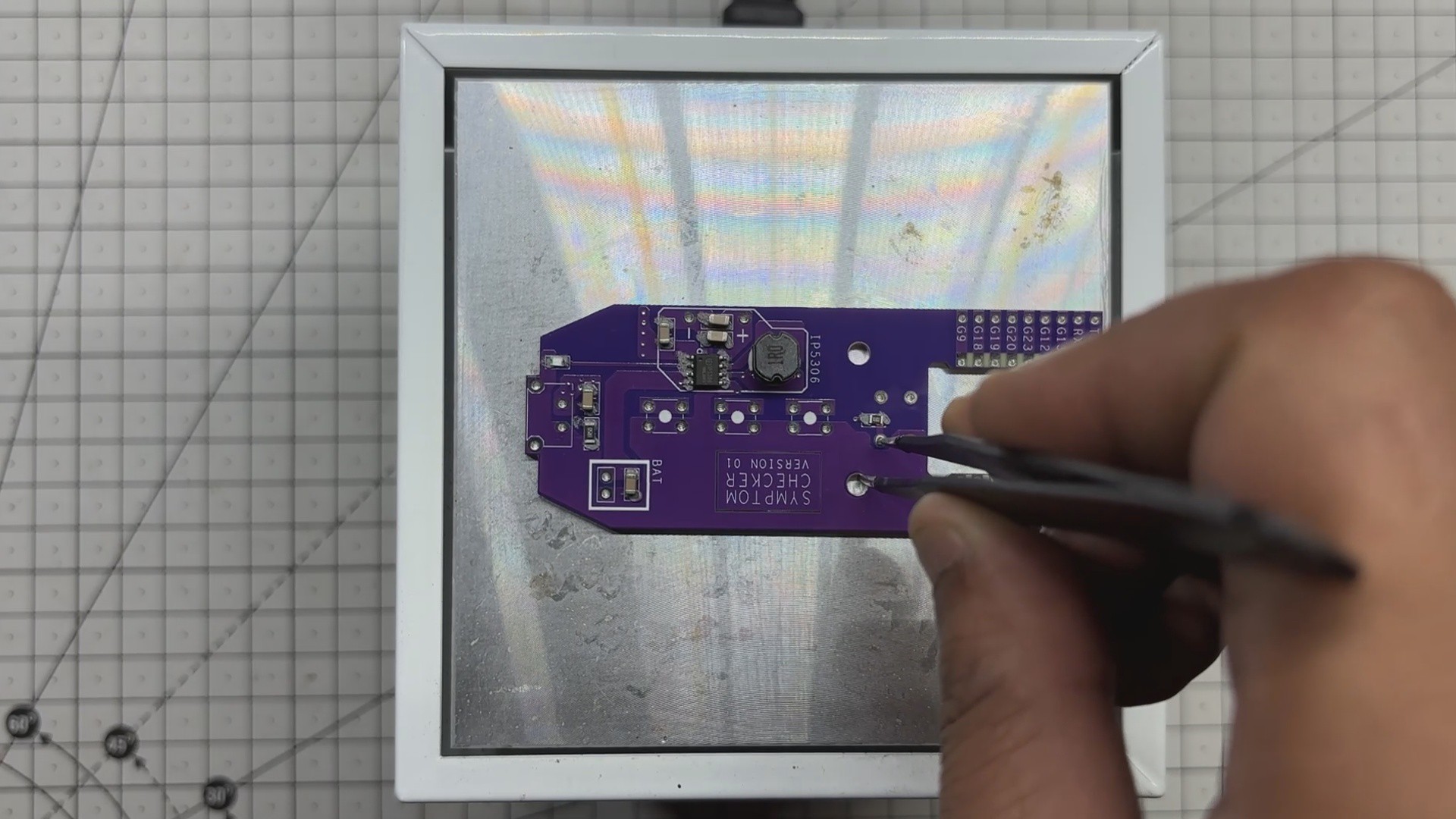
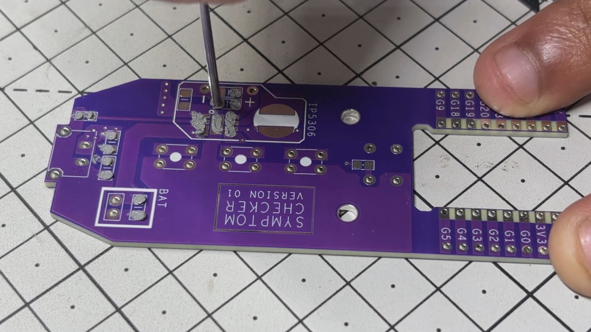
- We start the PCB assembly process by applying solder paste to each SMD component pad using a solder paste syringe. We’re using 63-37 SnPb paste, which has a melting temperature of 200°C.
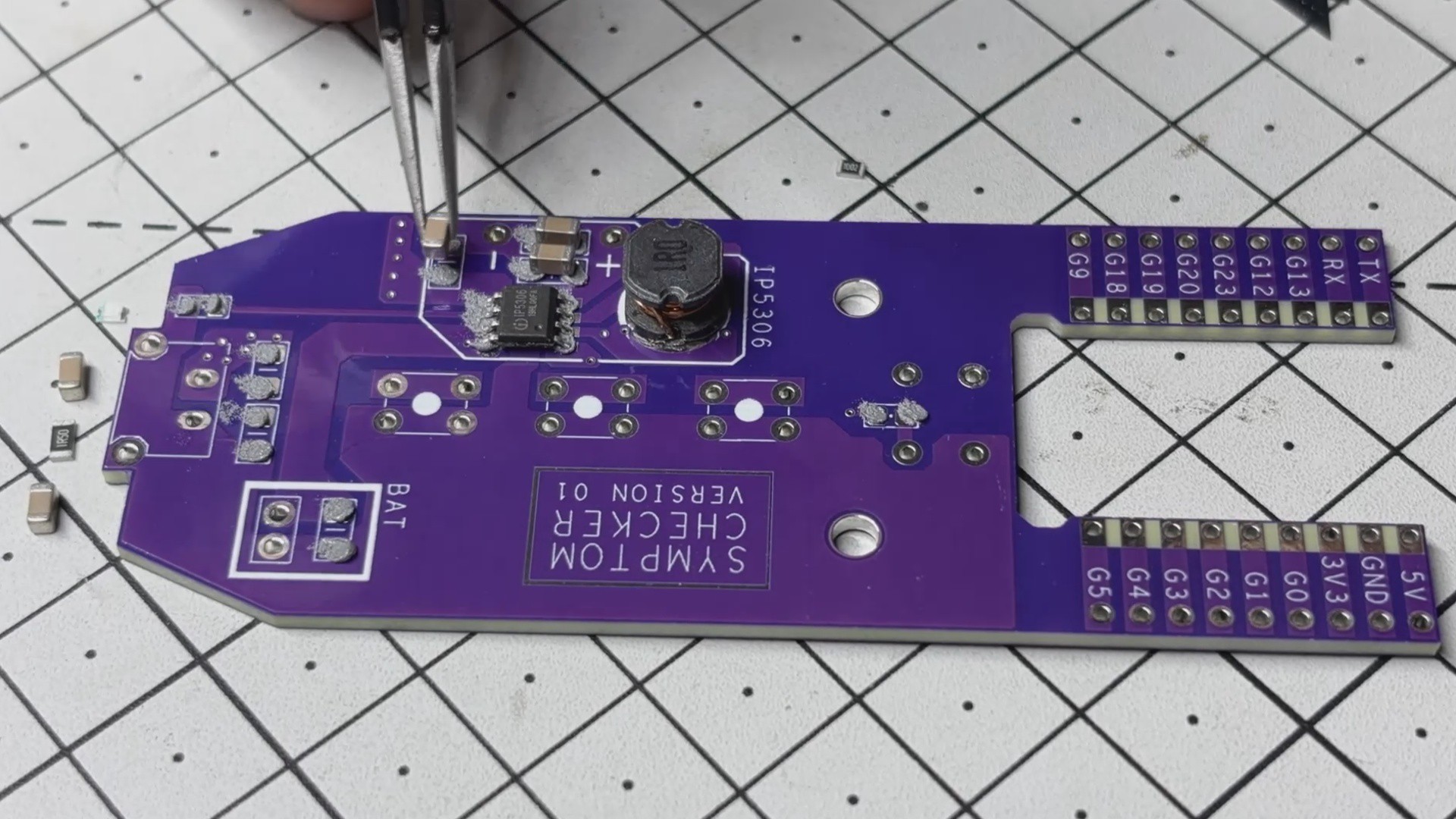
- Next, we begin the pick-and-place process, which involves picking up SMD components using ESD tweezers and placing them in their designated locations.
- Once placed, we lift the circuit and set it on our SMD reflow hotplate. The hotplate heats the PCB from below until it reaches the solder paste’s melting temperature. As soon as the PCB hits 200°C, the solder paste melts and secures the components to the board.
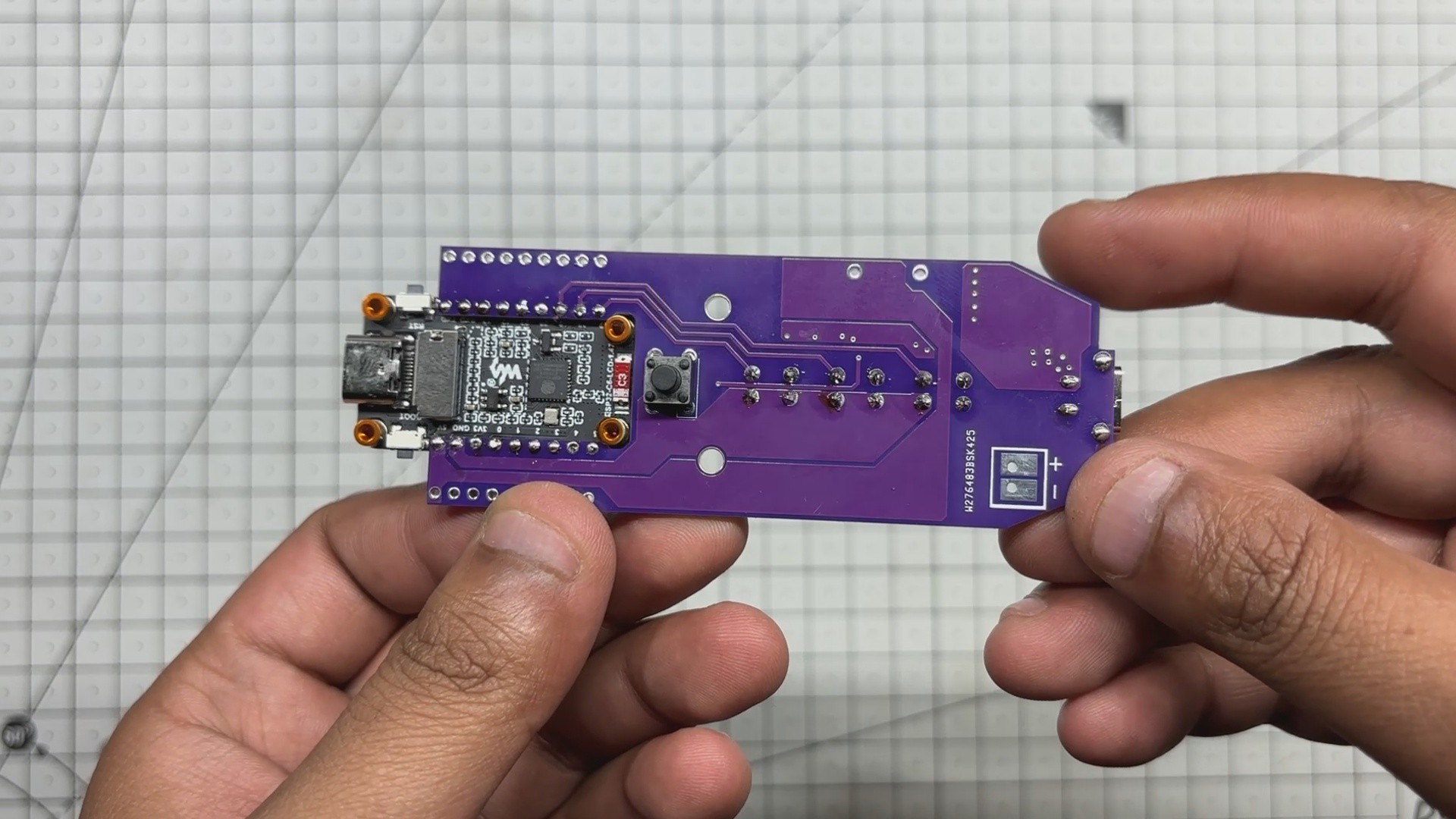
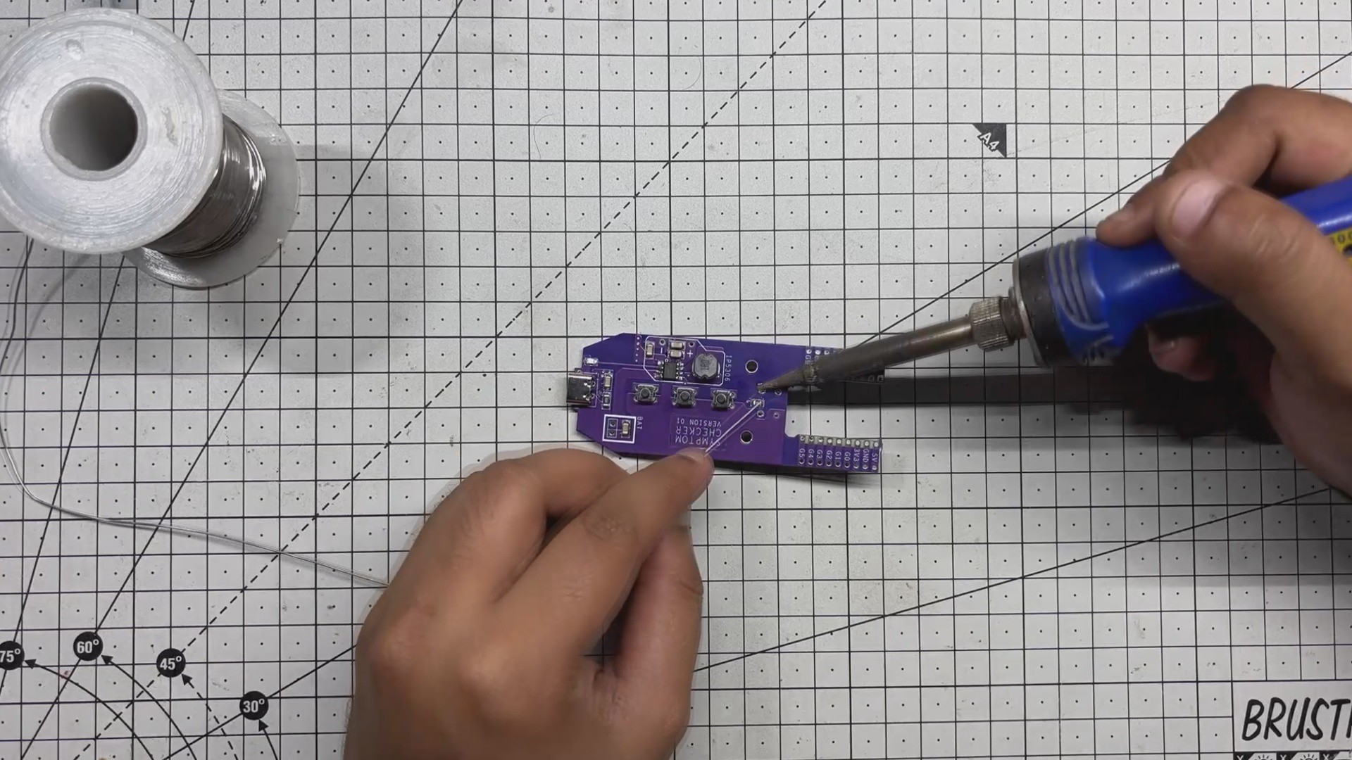
- After that, we place a 6×6 tactile switch on the bottom side of the PCB and solder it in place using a soldering iron.
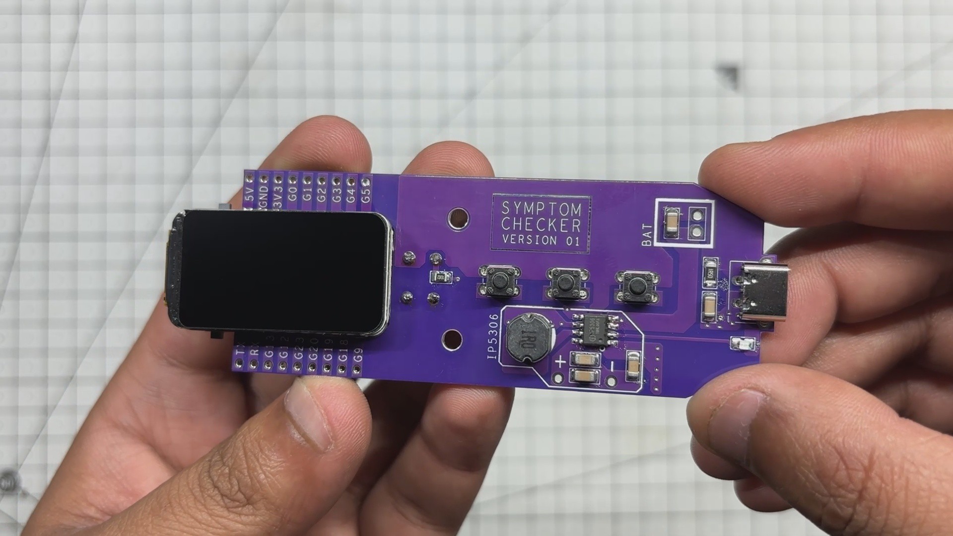
- The rest of the through-hole components are added from the top side, including three 4×4 tactile switches and one Type-C port.
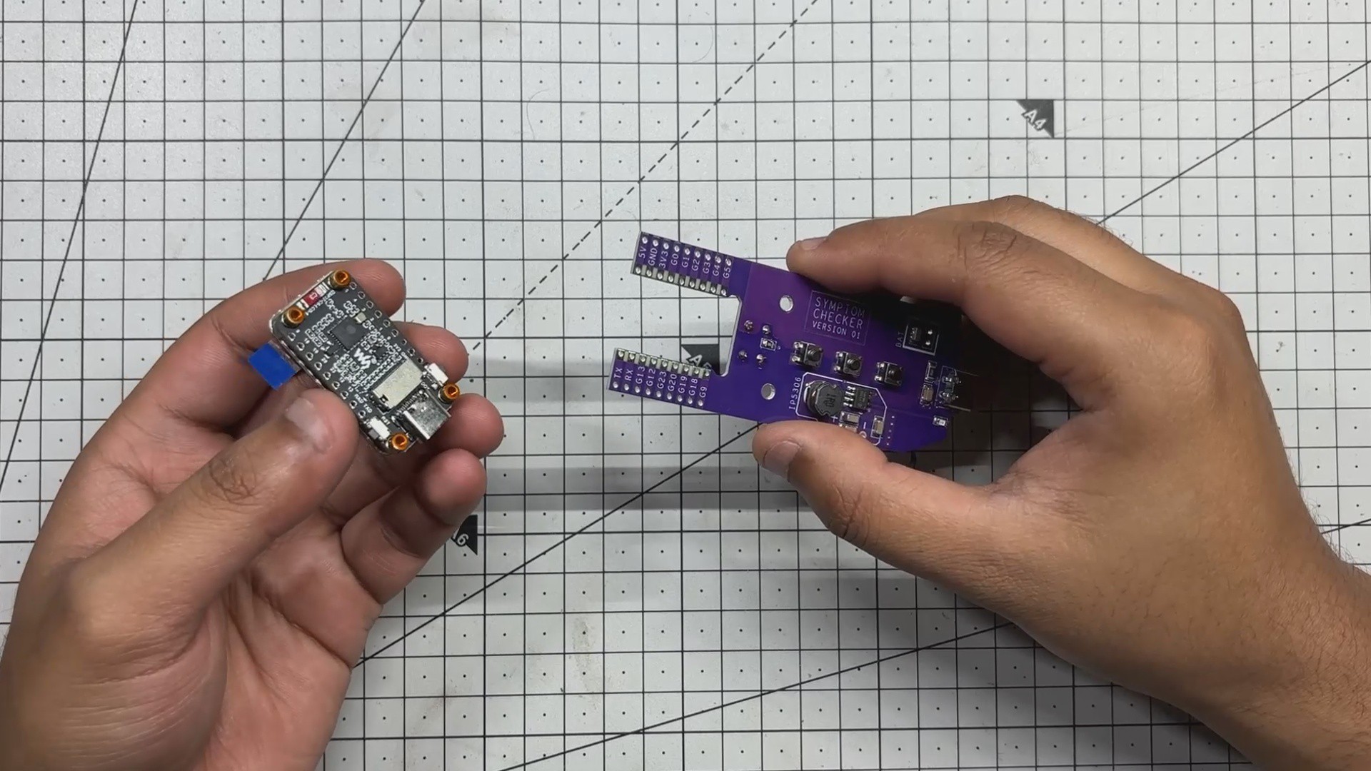
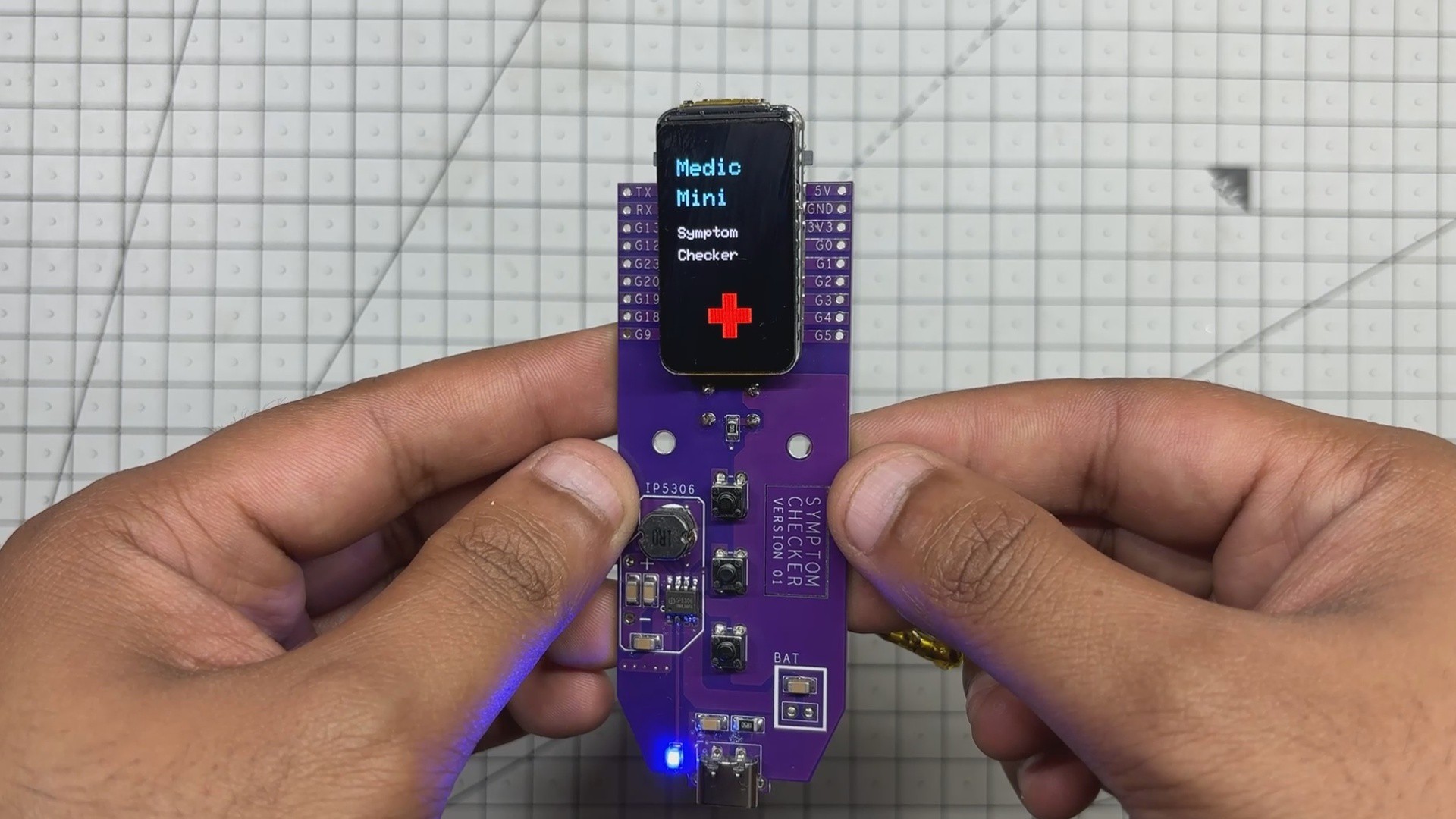
- Finally, we place the Waveshare ESP32 board in its position and solder it using a soldering iron. We simply align it over the mounting pads and use excess solder on each pad to join the ESP32 board to the PCB.
-
2POWER SOURCE
![]()
![]()
![]()
![]()
![]()
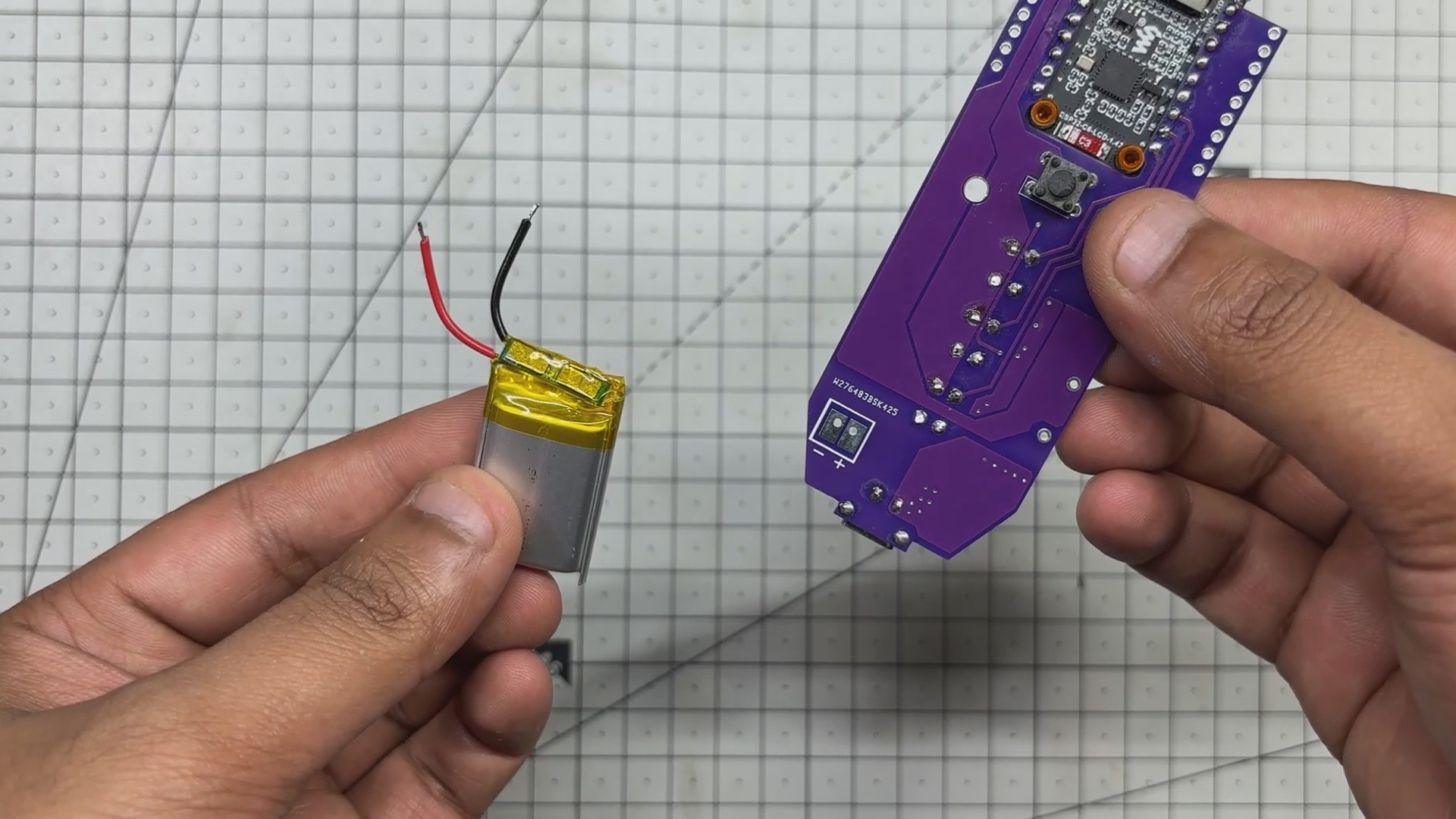
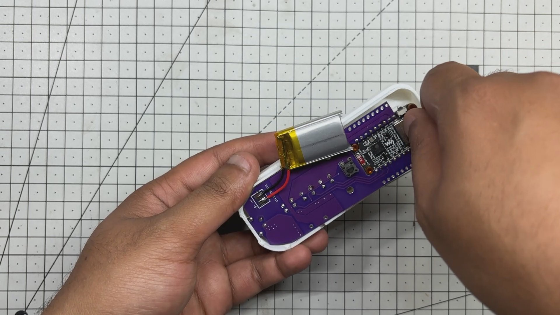
For the power source of this project, we are utilizing a 3.7V 600mAh Li-Po cell, which can provide a total runtime of more than 10 hours, which is pretty decent, considering we won’t be using it continuously. After diagnosing, we can turn the device OFF, which gives us a backup of 2–3 days depending on usage.
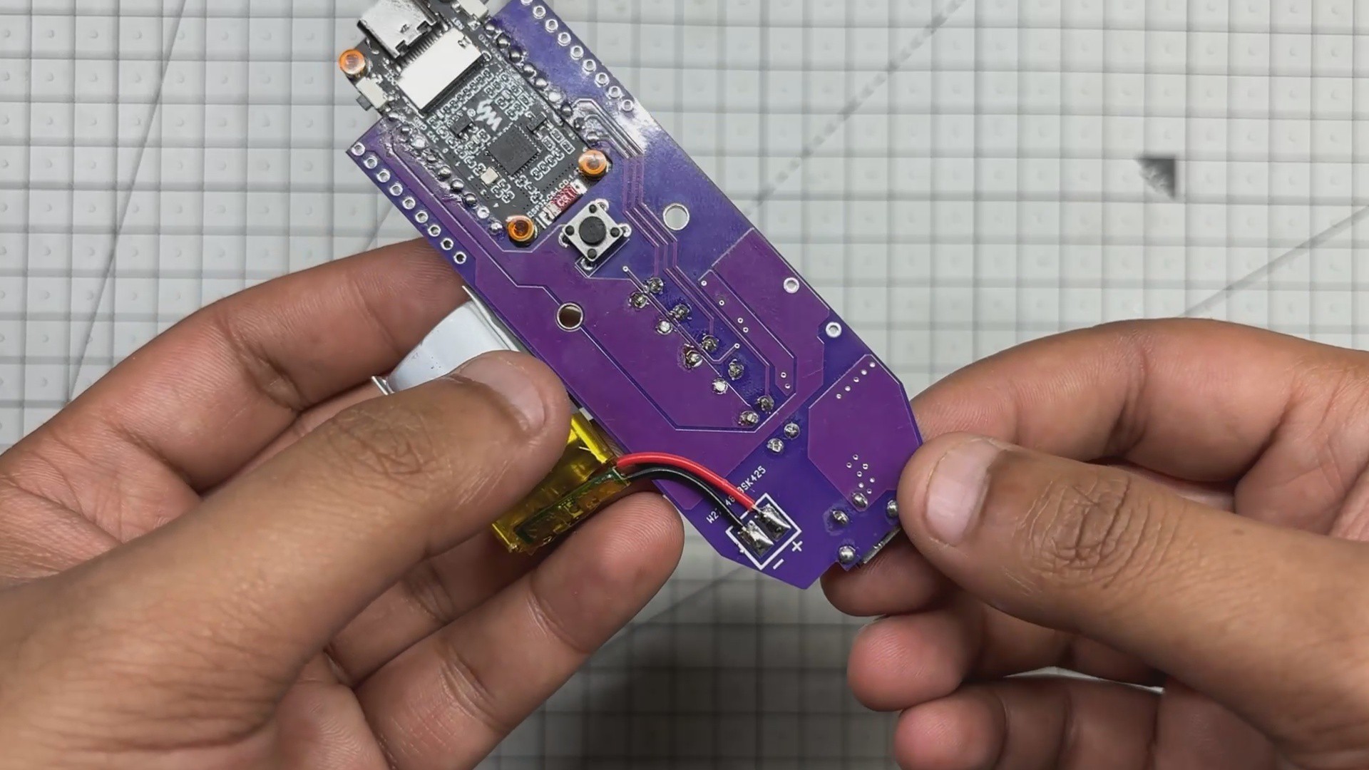
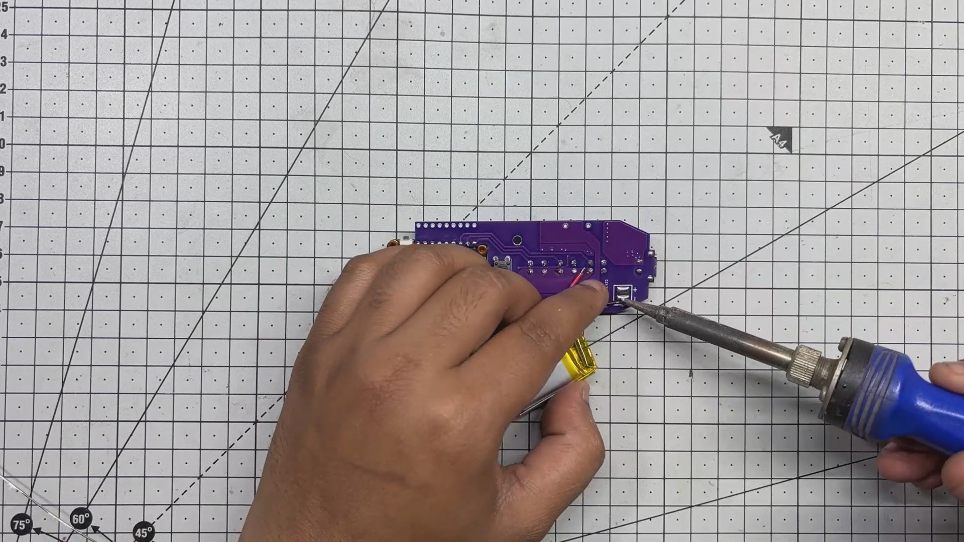
We solder the positive and negative terminals of the lithium cell to the battery connectors provided on the circuit.
By pressing the 6×6 tactile switch added on the backside of the circuit, the device turns ON. Double-tapping the switch turns the device OFF.
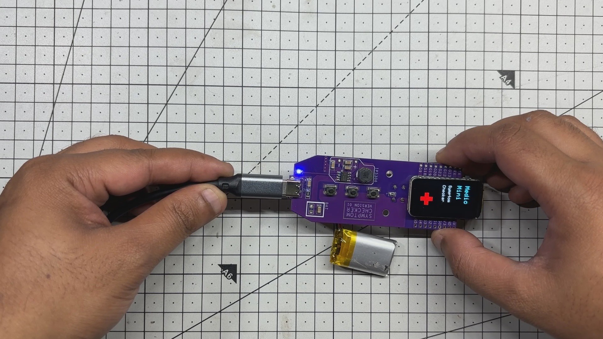
We can also charge this setup by plugging in a 5V supply via the provided Type-C port. During charging, the indicator LED will blink, and it turns stable once the lithium cell is fully charged.
-
3CODE for Waveshare ESP32 C6 1.47 Display
This is the finalized code running on the Medic Mini device. It differs slightly from our earlier demo sketch due to changes in the display and I/O configuration. The demo version used an ILI9341 display with the ESP32-C6 DevKit, which required a different set of GPIO assignments and library setup.
In contrast, the final build uses the Waveshare ESP32-C6 1.47" display module.
The below Breakdown highlights all the key differences introduced in this updated sketch.
#include

// LCD pin map for ESP32-C6
#define LCD_MOSI 6
#define LCD_SCLK 7
#define LCD_CS   14
#define LCD_DC   15
#define LCD_RST  21
#define LCD_BL   22
// Button pins
#define BTN_YES     9
#define BTN_NO      18
#define BTN_UNSURE  19
const char* symptoms[] = {
"Headache",
"Fever",
"Cough",
"Fatigue",
"Nausea"
};
const int symptomCount = sizeof(symptoms) / sizeof(symptoms[0]);
int responses[symptomCount]; // -1 = not answered, 0 = No, 1 = Yes, 2 = Not Sure
int currentSymptom = -1;
bool symptomDrawn = false;
enum ScreenState {
SCREEN_STARTUP,
SCREEN_SYMPTOM,
SCREEN_RESULT
};
ScreenState currentScreen = SCREEN_STARTUP;
ScreenState lastScreen = SCREEN_STARTUP;
// Button states
bool lastYes = false;
bool lastNo = false;
bool lastUnsure = false;
unsigned long lastInputTime = 0;
const unsigned long inputLockout = 300;
Arduino_DataBus *bus = new Arduino_ESP32SPI(
LCD_DC, LCD_CS, LCD_SCLK, LCD_MOSI, GFX_NOT_DEFINED
);
Arduino_GFX *gfx = new Arduino_ST7789(
bus,
LCD_RST,
2,
true,
172,
320,
34, 0,
34, 0
);
// Stable press detection
bool isStablePress(int pin, bool& lastState) {
bool current = digitalRead(pin) == LOW;
bool pressed = current && !lastState;
lastState = current;
return pressed;
}
void drawStartup() {
gfx->fillScreen(BLACK);
// Title split: Medic / Mini
gfx->setTextSize(3);
gfx->setTextColor(CYAN);
gfx->setCursor(20, 40);
gfx->println("Medic");
gfx->setCursor(20, 80);
gfx->println("Mini");
// Subtitle split: Symptom / Checker
gfx->setTextSize(2);
gfx->setTextColor(WHITE);
gfx->setCursor(20, 130);
gfx->println("Symptom");
gfx->setCursor(20, 160);
gfx->println("Checker");
// Red medical plus sign
gfx->fillRect(80, 220, 20, 60, RED);  // vertical bar
gfx->fillRect(60, 240, 60, 20, RED);  // horizontal bar
}
void drawSymptomPrompt(const char* symptom, int response) {
gfx->fillScreen(BLACK);
gfx->setTextSize(2);
gfx->setTextColor(WHITE);
gfx->setCursor(10, 80);
gfx->println("Do you have");
gfx->setCursor(10, 110);
gfx->print(symptom);
gfx->println("?");
// Centered response label
gfx->setTextSize(3);
int centerX = 86;
if (response == 1) {
gfx->setTextColor(GREEN);
gfx->setCursor(centerX - 30, 180);
gfx->println("Yes");
} else if (response == 0) {
gfx->setTextColor(RED);
gfx->setCursor(centerX - 30, 180);
gfx->println("No");
} else if (response == 2) {
gfx->setTextColor(YELLOW);
gfx->setCursor(centerX - 70, 180);
gfx->println("Not Sure");
}
}
void drawResult() {
gfx->fillScreen(BLACK);
gfx->setCursor(10, 60);
gfx->setTextSize(2);
gfx->setTextColor(GREEN);
gfx->println("Processing...");
delay(1000);
int yesCount = 0;
for (int i = 0; i < symptomCount; i++) {
if (responses[i] == 1) yesCount++;
}
gfx->fillScreen(BLACK);
gfx->setTextSize(2);
gfx->setTextColor(WHITE);
if (yesCount >= 3) {
gfx->setCursor(10, 100);
gfx->println("Possible");
gfx->setCursor(10, 170);
gfx->println("match:");
gfx->setCursor(10, 210);
gfx->setTextColor(YELLOW);
gfx->println("Flu or Viral");
} else if (yesCount == 2) {
gfx->setCursor(10, 100);
gfx->println("Mild symptoms");
gfx->setCursor(10, 140);
gfx->println("Monitor &");
gfx->setCursor(10, 170);
gfx->println("rest");
} else {
gfx->setCursor(10, 100);
gfx->println("No major");
gfx->setCursor(10, 140);
gfx->println("match found");
}
gfx->setCursor(10, 200);
gfx->setTextSize(1);
gfx->setTextColor(CYAN);
gfx->println("Press YES to restart");
}
void setup() {
pinMode(LCD_BL, OUTPUT);
digitalWrite(LCD_BL, HIGH);
pinMode(BTN_YES, INPUT_PULLUP);
pinMode(BTN_NO, INPUT_PULLUP);
pinMode(BTN_UNSURE, INPUT_PULLUP);
for (int i = 0; i < symptomCount; i++) {
responses[i] = -1;
}
gfx->begin();
drawStartup();
}
void loop() {
unsigned long now = millis();
if (currentScreen != lastScreen) {
if (currentScreen == SCREEN_STARTUP) {
drawStartup();
} else if (currentScreen == SCREEN_RESULT) {
drawResult();
}
lastScreen = currentScreen;
}
if (currentScreen == SCREEN_SYMPTOM &&
currentSymptom < symptomCount &&
!symptomDrawn) {
drawSymptomPrompt(symptoms[currentSymptom], responses[currentSymptom]);
symptomDrawn = true;
}
if (currentScreen == SCREEN_STARTUP &&
(isStablePress(BTN_YES, lastYes) || isStablePress(BTN_NO, lastNo) || isStablePress(BTN_UNSURE, lastUnsure))) {
currentSymptom = 0;
currentScreen = SCREEN_SYMPTOM;
symptomDrawn = false;
delay(300);
}
if (currentScreen == SCREEN_SYMPTOM && currentSymptom < symptomCount) {
if (now - lastInputTime > inputLockout) {
if (isStablePress(BTN_YES, lastYes)) {
responses[currentSymptom] = 1;
drawSymptomPrompt(symptoms[currentSymptom], 1);
delay(500);
currentSymptom++;
symptomDrawn = false;
lastInputTime = now;
} else if (isStablePress(BTN_NO, lastNo)) {
responses[currentSymptom] = 0;
drawSymptomPrompt(symptoms[currentSymptom], 0);
delay(500);
currentSymptom++;
symptomDrawn = false;
lastInputTime = now;
} else if (isStablePress(BTN_UNSURE, lastUnsure)) {
responses[currentSymptom] = 2;
drawSymptomPrompt(symptoms[currentSymptom], 2);
delay(500);
currentSymptom++;
symptomDrawn = false;
lastInputTime = now;
}
if (currentSymptom >= symptomCount) {
currentScreen = SCREEN_RESULT;
}
}
}
if (currentScreen == SCREEN_RESULT && isStablePress(BTN_YES, lastYes)) {
for (int i = 0; i < symptomCount; i++) {
responses[i] = -1;
}
currentSymptom = 0;
currentScreen = SCREEN_SYMPTOM;
symptomDrawn = false;
delay(300);
}
}
In our main sketch, we use the Arduino GFX Library to drive the ST7789 display.
The following configuration sets up the screen dimensions, rotation, and offset parameters tailored to the Waveshare ESP32-C6 1.47" module.
Arduino_GFX *gfx = new Arduino_ST7789(bus,LCD_RST,2, // rotationtrue, // IPS172, // width320, // height34, 0, // X offset34, 0 // Y offset);
We configured the pin mapping to match the default wiring of the Waveshare ESP32-C6 1.47" display. These assignments were based on the official Waveshare Wiki documentation.
#define LCD_MOSI 6#define LCD_SCLK 7#define LCD_CS 14#define LCD_DC 15#define LCD_RST 21#define LCD_BL 22
Next comes the button input.
#define BTN_YES 9#define BTN_NO 18#define BTN_UNSURE 19
The rest of the code logic remains unchanged from the previous demo sketch. The only modifications made here are the updated display configuration and revised input button mappings to match the final hardware.
We uploaded the code into our ESP32 board and moved onto the next step, which was the enclosure assembly. From next, we cannot upload code into ESP32 because its USB will be inaccessible.
-
4ENCLOSURE ASSEMBLY
![]()
![]()
![]()
![]()
![]()
![]()
![]()
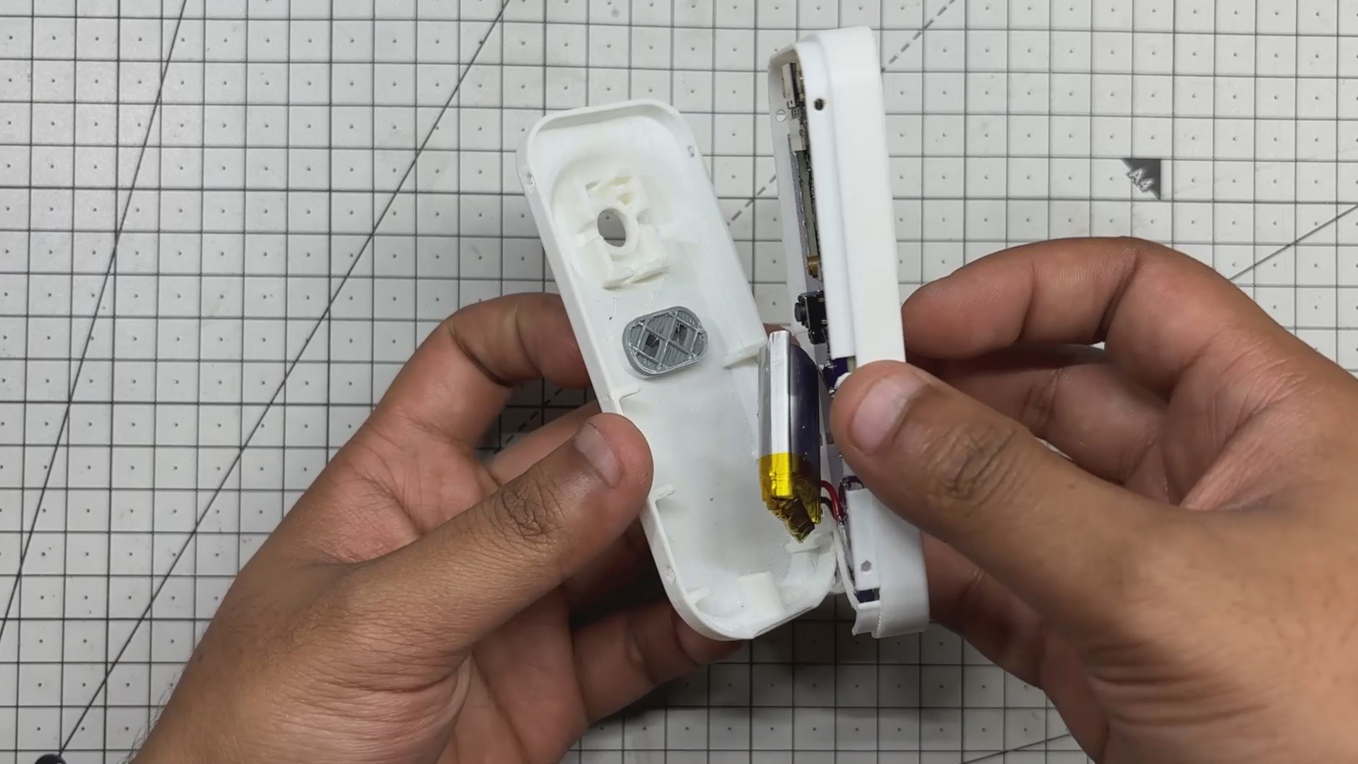
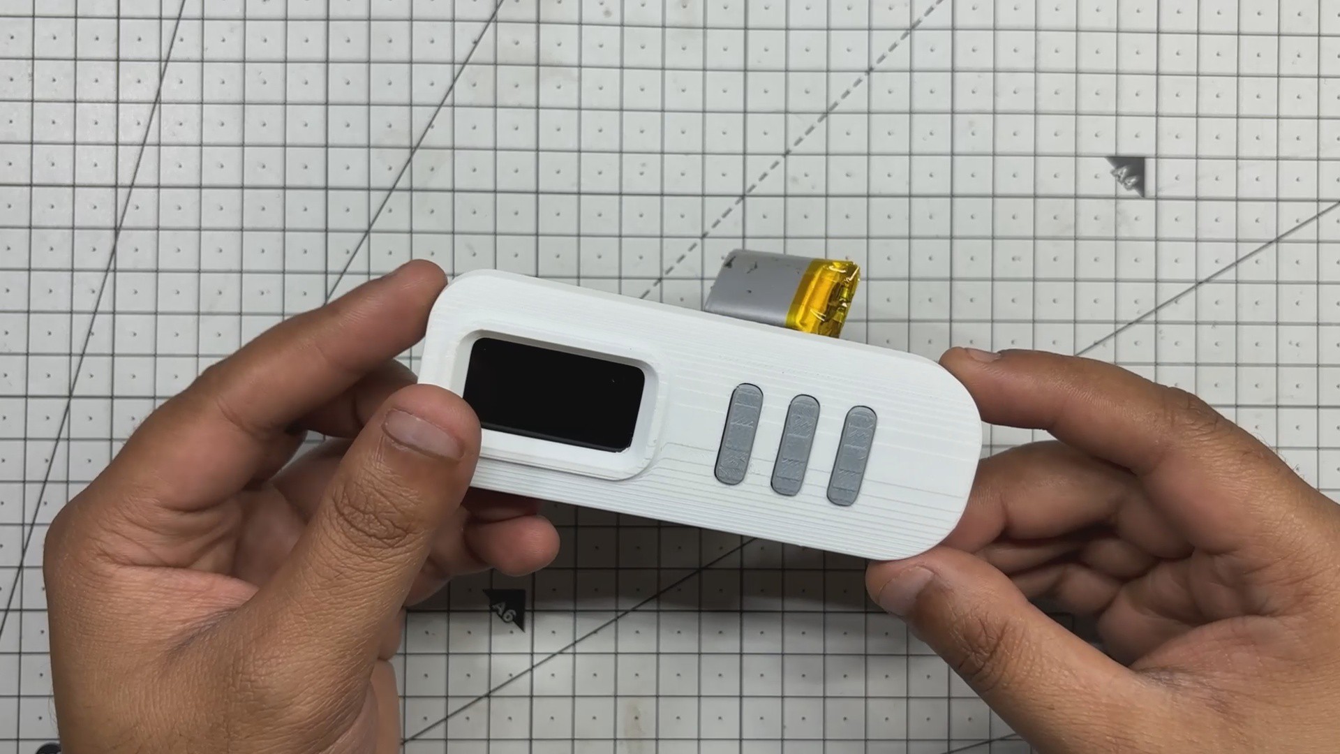
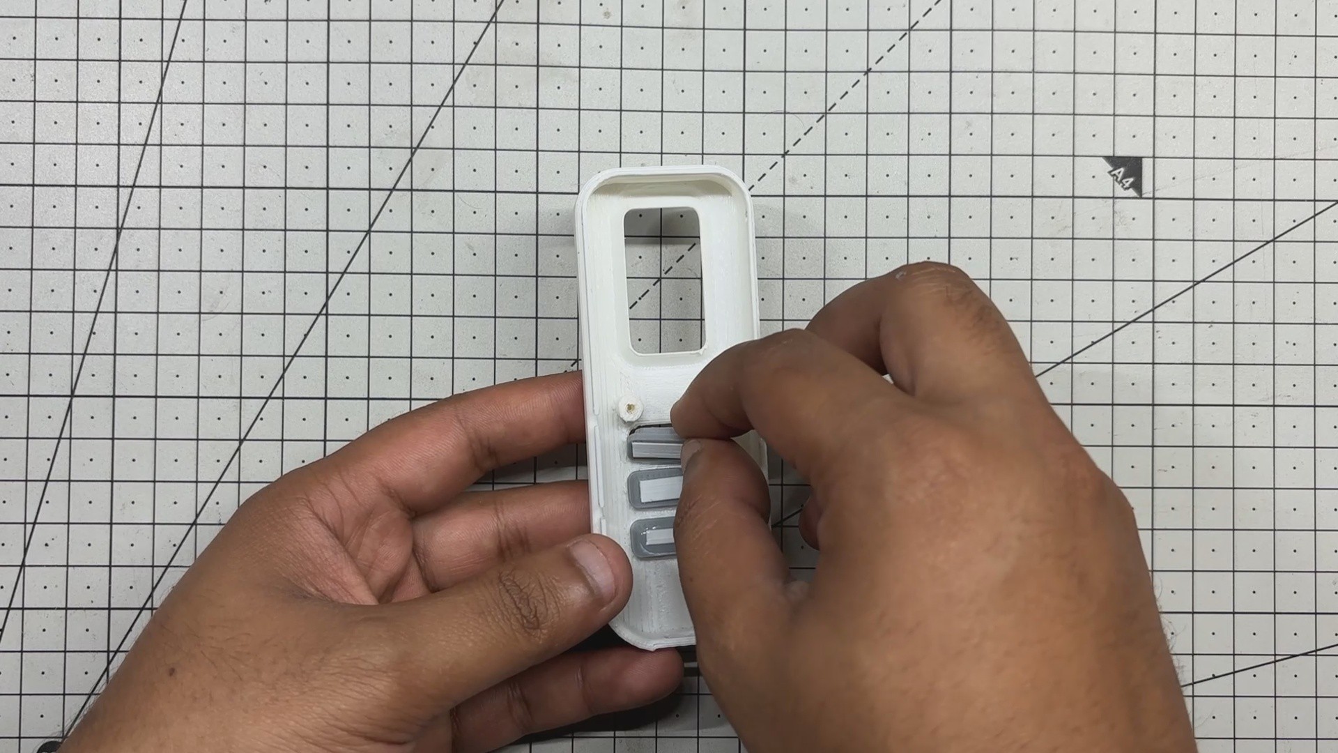
- The enclosure assembly begins by placing the switch actuators into the front half of the body. Next, we position the circuit board over the screw bosses and secure it using two M2 screws.
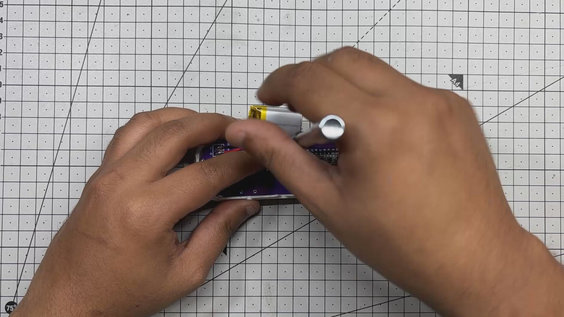
- A strip of double-sided tape is applied to the back of the LiPo cell, which is then pressed firmly onto the circuit to hold it in place.
- After that, we align the back half of the enclosure with the front and fasten them together using four M2 screws, completing the full assembly of the device.
-
5RESULT
![]()
![]()
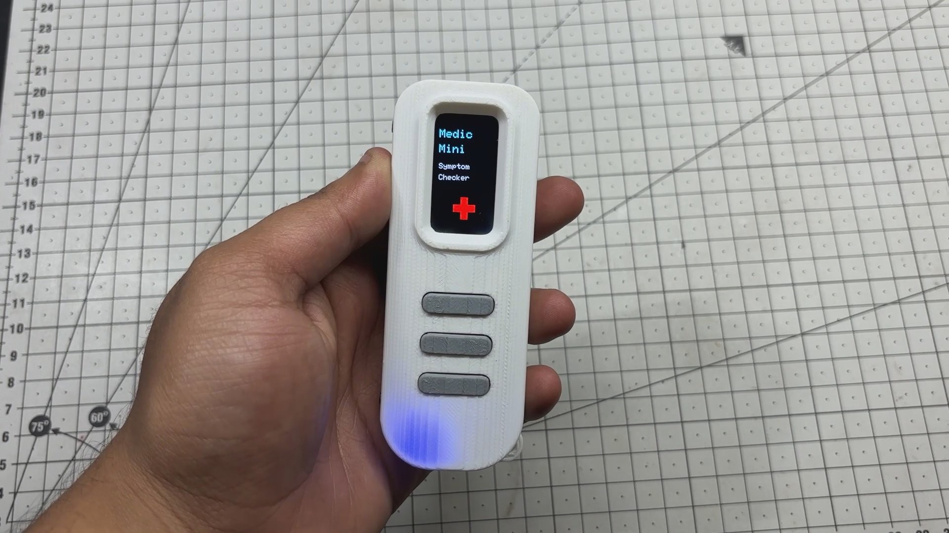
After completing the build, I tested Medic Mini by running through the symptom checker and sure enough, I was greeted with a “Fever” message based on my inputs.
The logic works as intended, and the device responds quickly and accurately to button presses. It’s a solid proof of concept for a portable, interactive diagnostic tool.
That said, this is just the beginning. To truly elevate Medic Mini to a practical, real-world level, we’ll need to consult with medical professionals and gather validated symptom data. This will help refine the logic and ensure the device aligns with actual diagnostic standards.
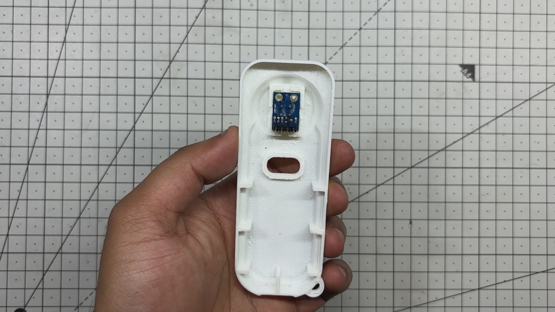
Looking ahead, I plan to expand the project by integrating additional medical sensors in future revisions, starting with an infrared temperature sensor (MLX90614) and eventually adding support for heart rate, SpO₂, and other vitals. The goal is to turn Medic Mini into a compact, multi-sensor health assistant that’s both accessible and reliable.
-
6VERSION 2
![]()
For version 2 of this project, I’m planning to integrate sensors to collect real-time health data. The first upgrade will be the MLX90614 infrared temperature sensor, which will let us measure body temperature without contact. That data can then be fed directly into the symptom checker logic.
Overall, this setup was finished, and I would like to make revisions to this project in the future to further add sensors, helping expand Medic Mini’s diagnostic capabilities beyond just button-based input.
Thanks for reaching this far, and I will be back with a new project pretty soon.
Peace.
MEDIC Mini
Medic Mini is a handheld ESP32-C6 device that checks symptoms using simple button inputs.



Discussions
Become a Hackaday.io Member
Create an account to leave a comment. Already have an account? Log In.