Close
0%
0%

Relay as a magnetic guitar pickup

Hexaphonic guitar puckup built from 6 unmodified relays and amplifiers

Similar projects worth following
A typical magnetic guitar pickup senses vibrating magnetized strings with a big coil, which has lots of windings of very thin wire.

You know what component also has a coil with lots of windings of very thin wire? Well, a lot of them, actually, but among others relay usually has a pretty similar coil construction. Sure, the coil of a relay is there to produce magnetic field (to move contacts to connect them), not to be influenced by an external field, but, you know, every electric motor is a generator if you're brave enough, or whatever they say.

I've made a guitar pickup out of 6 relays, each sensing one string. It can be a totally normal pickup (just built from weird components), but it can also do something, regular pickups can not. I've made a board that mixes 6 channels into 2 for using same guitar with 2 different effect chains. It can be potentially used for easier polyphonic MIDI tracking, which is hard with monophonic pickups.

I always kinda wanted a guitar pickup that selectively picks vibrations of every string individually, having 6 separate independent outputs. Wanted not badly enough to justify buying one of commercial units, which exist and are not that expensive, or building my own.

After winding my own one-string guitar pickup for a one-string guitar (that was a separate project) I thought, maybe I will give it a go, it's not that hard after all. I've also seen one DIY attempt on the internet of building such a pickup using tape heads, which are basically also coils, just with fancy magnetic circuit around.

Later when reading about the component abuse challenge on Hackaday something clicked in my brain. In the description an ignition coil was mentioned and I thought "hey, every coil is a pickup coil if you're brave enough". Not just tape heads, but electric motors, magnetic valves, ignition coils, wireless charging modules, lots of stuff has coils inside, which could pick some of the magnetic field of a vibrating magnetized string.

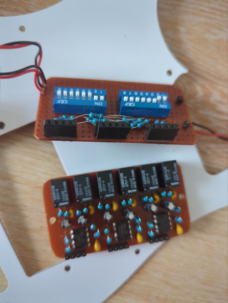
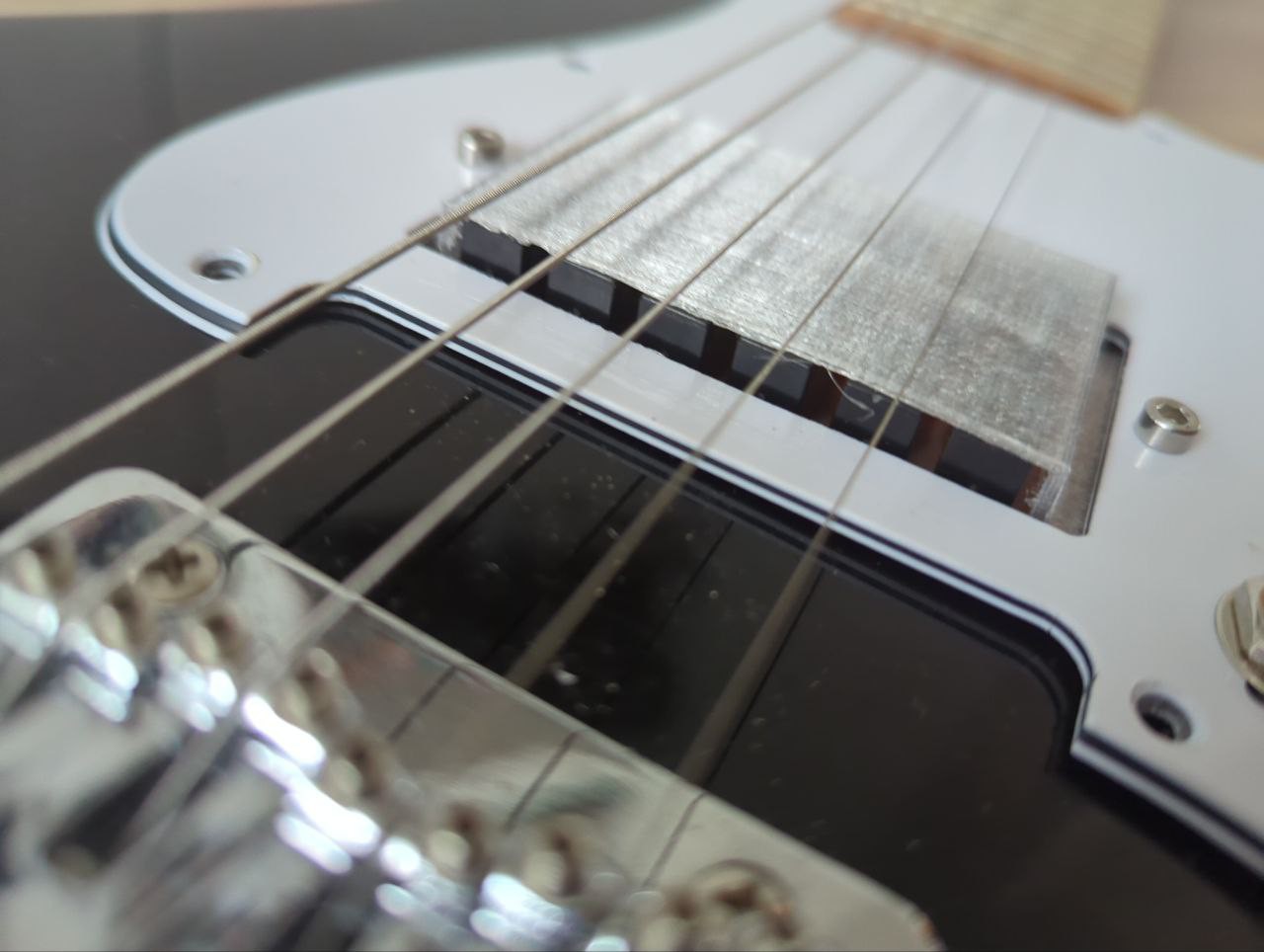
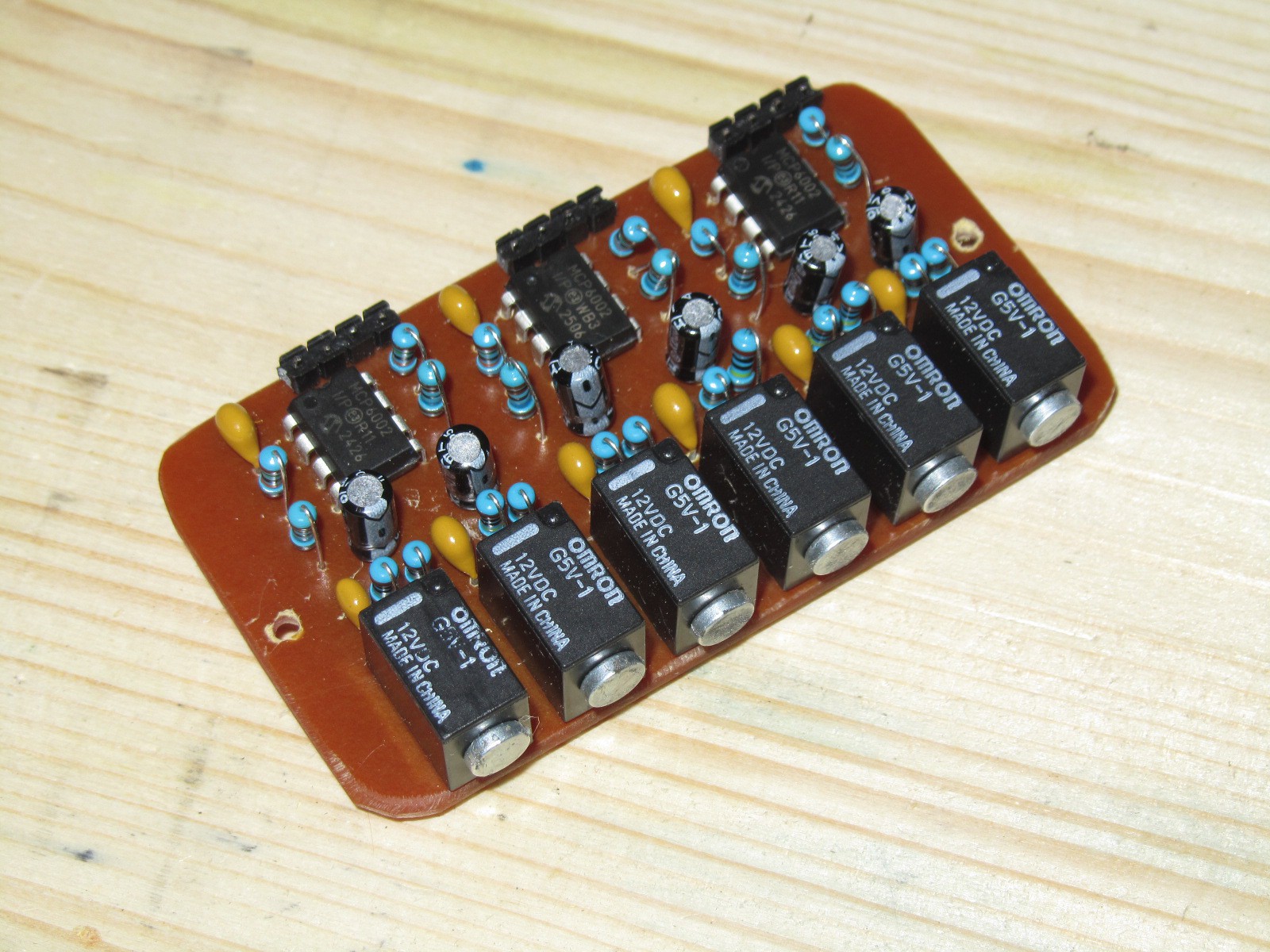
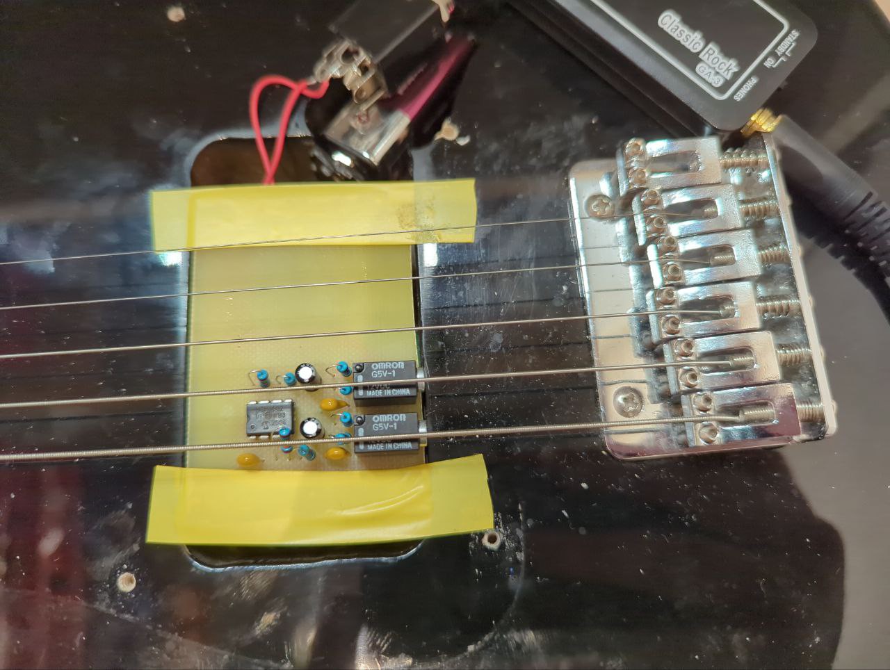
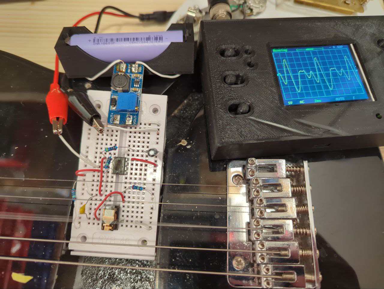
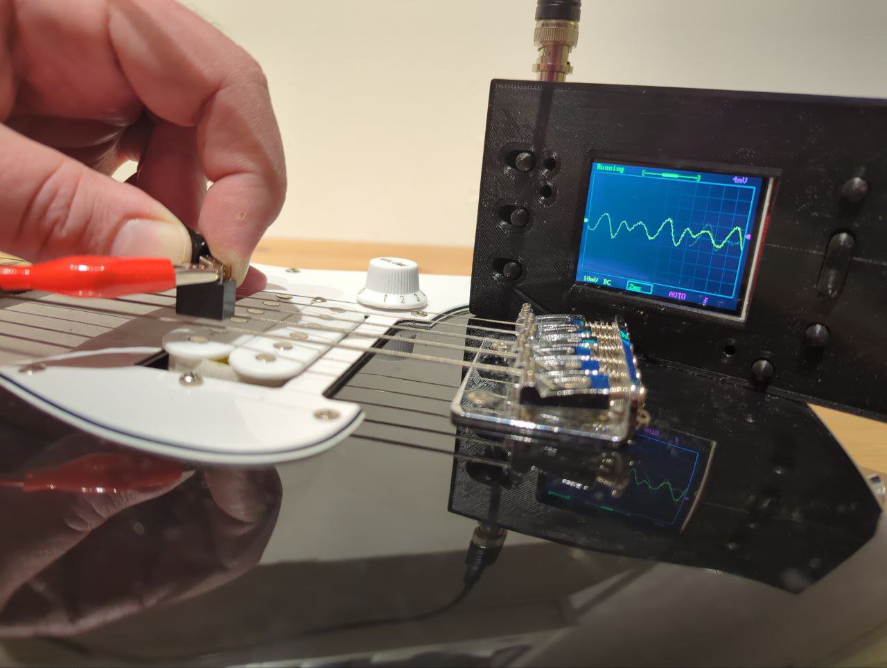
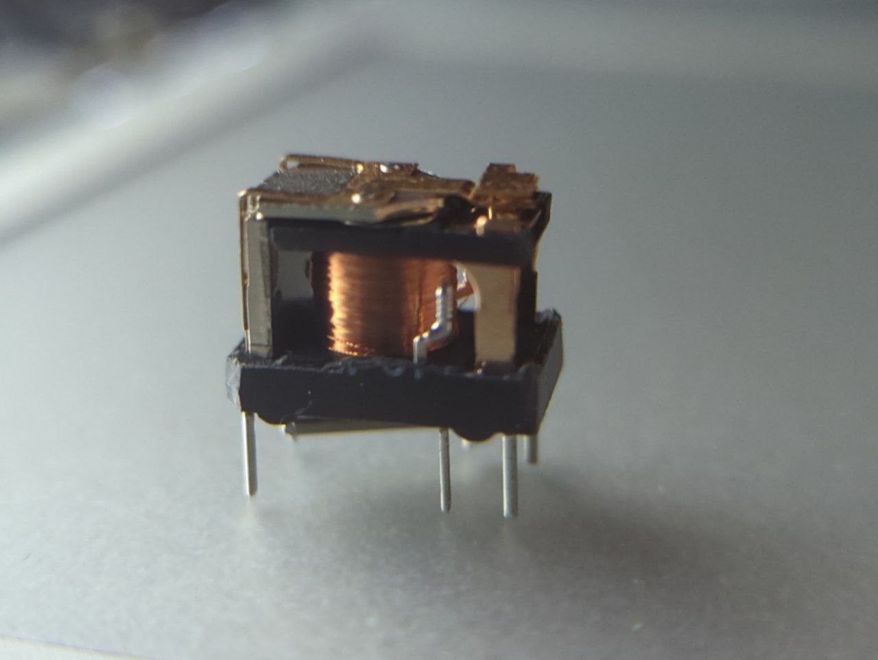
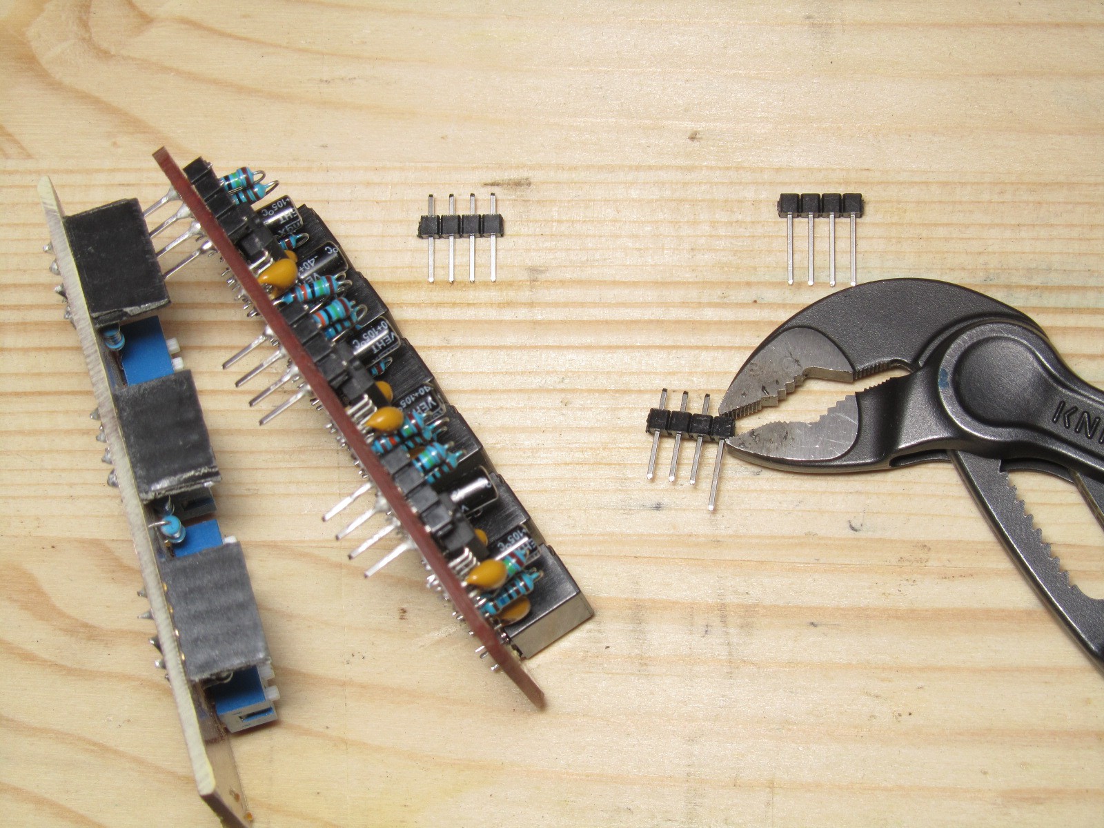
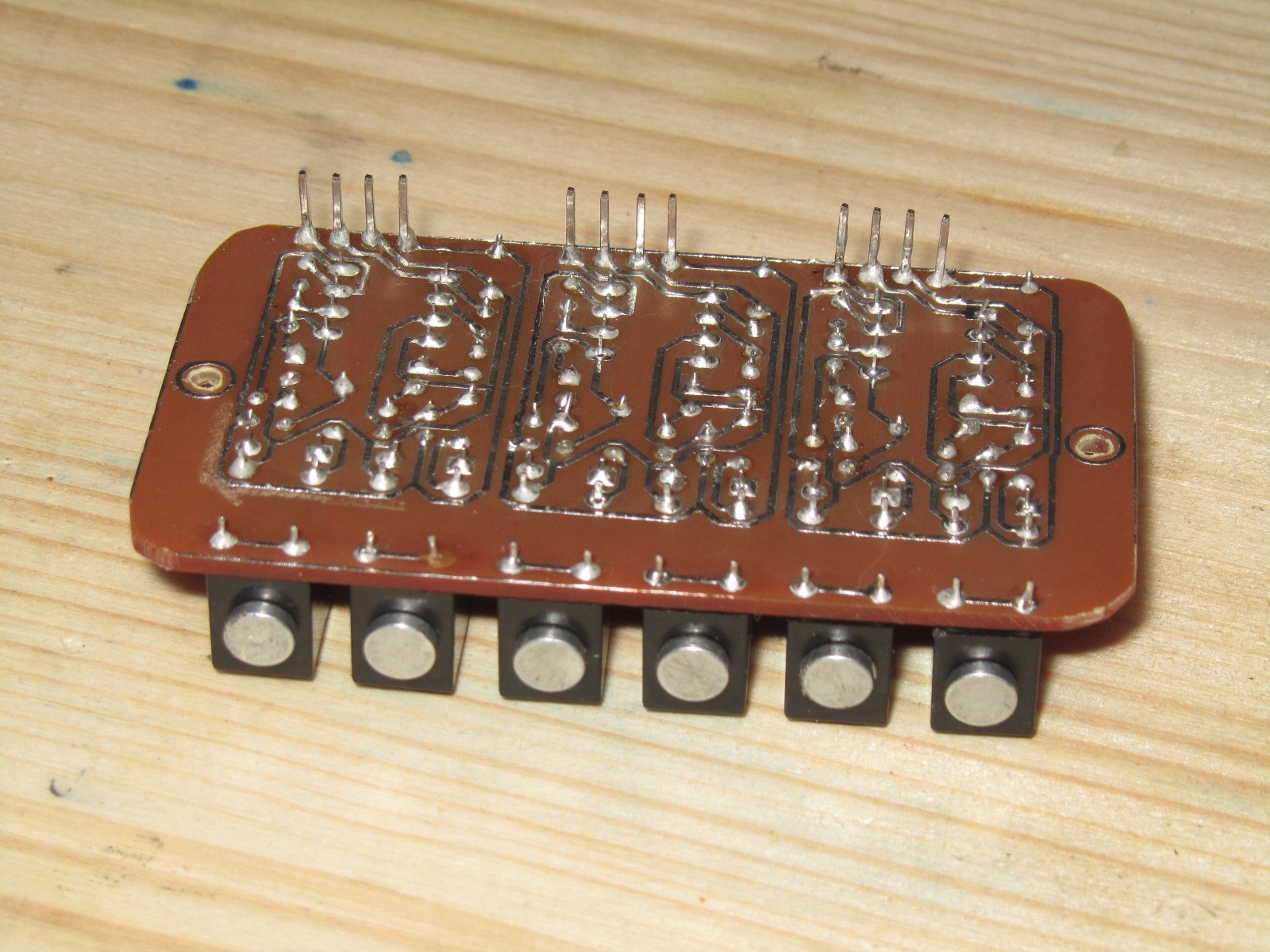
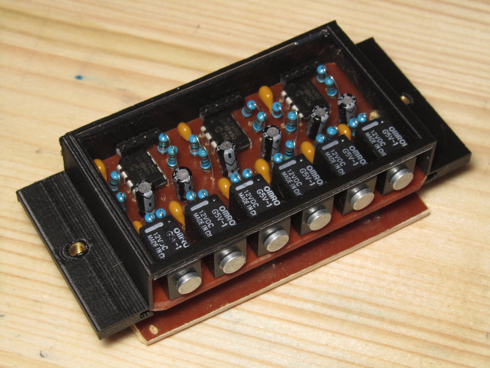
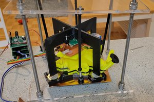
Not gonna lie, I've also seen coils taken from relays used as pickup coils on a DIY-pickup on the internet. But I didn't want to go that way, I wanted to abuse the component, not kill it and use its internals for something else. I tested if the coil of an unmodified relay can give a usable signal and it did! I learned what I needed to amplify the signal in a couple of weeks and built a fully functional hexaphonic pickup. It's surprisingly good for what it is: the coil of a relay is designed to produce magnetic field almost exclusively within the magnetic circuit it's wound around, leaving just a small gap for the contact motion, but that gap is enough for the magnetic field of the string to get inside of this circuit.

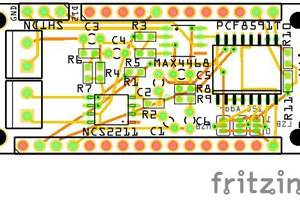
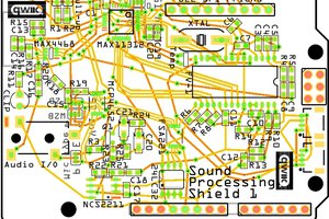
Now there are several ways to use this setup. It can be used just as a gimmick, a totally normal pickup made of unnecessarily abused components. Or it can do something, regular pickups cannot do. First of all, I've made a board that mixes 6 signals from 6 strings to two channels. It can be used as a stereo effect such that different strings sound like they're coming from different "directions", or it can be used to apply different effects to different strings, as if one plays two different guitars connected to two different signal chains/amps/speakers.

The second thing I want to do in future is polyphonic MIDI-output. It is pretty tricky to recognize several notes being played simultaneously if all you have is a mix of those notes sounding together. Most DIY guitar MIDI trackers are monophonic. By having access to 6 separate signals and having computing power of 6 guitar tuners combined it should be possible to make a proper polyphonic instrument. Wait for the updates.

enclosure_window.stl

STL model of a pickup cover, used in photos and build instructions

Standard Tesselated Geometry - 36.80 kB - 11/09/2025 at 19:51

Download

enclosure_no_window.stl

STL model of a pickup cover used in video

Standard Tesselated Geometry - 35.43 kB - 11/09/2025 at 19:49

Download

enclosure.scad

OpenSCAD model of pickup enclosure

scad - 762.00 bytes - 11/09/2025 at 19:47

Download

hexotracker.kicad_sch

schematics of one 2-string submodule and of mixer board

x-kicad-schematic - 120.57 kB - 11/09/2025 at 19:46

Download

hexotracker.kicad_pcb

traced PCBs of both the pickup and mixer

x-kicad-pcb - 477.88 kB - 11/09/2025 at 19:45

Download

  • 6 × Omron G5V-1 or similar relay
  • 9 × 100nF ceramic capacitor
  • 36 × 1M resistor
  • 6 × 1K6 resistor Electronic Components / Misc. Electronic Components
  • 6 × 150K resistor

View all 13 components

  • Video demo

    Kauz11/09/2025 at 19:39 0 comments

    I've recorded 3 demo snippets, showing what is possible with such a pickup. On all three the 2 bass strings are connected to some monophonic octave down effect (or two octaves down), while 4 treble strings are run through a different effect. In the first two snippets it is different overdrive simulations, and on the last one - also a monophonic synth, which allowed basically playing 2 notes on 2 synths simultaneously with just one guitar.

    I've updated the building instructions and now all that's left is upload KiCad files and 3d models for printing, and the project is done and ready for submitting!

  • Making it playable

    Kauz11/09/2025 at 12:33 0 comments

    Yeah, it's cool and that, but are we gonna make some sound? To be actually able to plug the guitar equipped with this pickup into something like an amp, we need to interface its 12-pin output with standard (in guitar world) 1/4 inch jack. To use the string separation property of it I put two output jacks into the guitar and made a mixer board with dip switches, that define which of the strings are present in which of two outputs. It's also possible to exclude some strings from both mixes, or to have them playing in two simultaneously, although that would increase the bleed of all strings into both mixes, it's a simplistic passive mixer.

    I've configured it such that two lowest strings go into one "bass" output, and the rest four into the other, because that's how I often divide the strings' roles when I'm playing bass and melody simultaneously (omg, I wish Lucas Brar played something on my guitar, my skills are not enough to use its full potential).

    The mixer board is the same size as the main pickup board, and may be mounted in a better way than just by friction in 12 pin/socket connections, but that'll do for now. I've designed a board holder with the same mounting points as on the guitar's original pickup, printed it in transparent PLA and soldered a 9v battery connector. The guitar is ready to be assembled and played!

  • Final 6-string prototype

    Kauz11/08/2025 at 20:39 0 comments

    As I always do when I'm making my own PCBs, I try to have as few tracks on the front side of the board as possible, and keep most of them on the back side. Single-sided boards are way easier to produce at home, and whatever needs to be connected on the second layer I just bridge with wires, instead of etching copper tracks.

    This time I managed to do all connections of a two-string submodule on a single layer, so I decided to just copy-paste as many of those submodules as needed and call it a day, instead of retracing the board as a whole. That means I don't get one 8-pin connector as I planned in the beginning, but rather three 4-contact connectors for each of three 2-string modules, each having own power-in which can be weird. But hey, lots of electronics nowadays has weird proprietary connections, sometimes unnecessarily complicated. Mine at least has documented pinout, and the weirdness of connections is not purposefully made to cause confusion (looking at you, inkjet cartridges).

    The positive side is that one can easily make 8-string version for contemporary metal guitar or a 4-string version for bass-guitar without much modifications. Just add or delete 2-string submodules, and move the relays just a little to fit the string spacing.


  • Test-mounting on the guitar

    Kauz11/08/2025 at 08:16 0 comments

    I've made the board to be the size of the humbucker, that came with this guitar, so I knew it would fit. But I still didn't figure out how I mount it on the pickguard yet. It's not that important on this stage. I've taped the PCB directly to the guitar body, connected the headphone amp and made some sounds. I placed small magnets on sides of the relays, they're just holding there by their own magnetic force.

    I'll post a video if I figure out how to upload it here :D

  • First PCB prototype

    Kauz11/08/2025 at 07:56 0 comments

    Once I've made sure the op amp of my choice (MCP6002-i/SN) does the job, I've designed a minimal sub-part of my future hexaphonic pickup. The idea was to have an 8-pin connector on the board in the end: 2 pins for ground and power and the rest 6 are signal outputs. This board would be connected to another module, for example a mixer, that mixes 6 channels into 2 for some stereo-effect, or ADC for digital signal output (like those weird Roland synth guitars that have proprietary digital connector), or ADC pins of some microcontroller capable of USB-MIDI, that would track the pitches of every string and return MIDI messages directly.

    Every IC has two op amps on board, so I made a two-channel prototype on a third of the board and had 4 connections out of final 8 output pins. After I made some scary sparks, by accidentally shorting power by conductive strings, I've decided to switch from 18650 cell to a humble 9v battery, at least for now, while nothing is really mounted securely.

  • Testing on breadboard

    Kauz11/06/2025 at 18:30 0 comments

    I've assembled a prototype on a breadboard as a sanity check and also for testing passive filtering. I still had hope that I can cut enough higher harmonics on each string so that the main frequency would have the highest amplitude of all (which is not always the case with normal string plucking).

    Well, the tests showed what I could've guessed beforehand: the highest playable note on each string is as high as two octaves above (so, fourth harmonic) the lowest playable note; therefore, there's no way to filter harmonics without dramatically dampening all of the notes on the higher frets. Well, quick and dirty MIDI tracking is out of scope now for sure.

    But at least I see that the amplifier works as intended and can transfer the content of the breadboard to a first prototype PCB.

  • Measuring with oscilloscope

    Kauz11/06/2025 at 18:27 0 comments

    I've got myself a DSO138 board, and did a little scope-creep-thingy by losing one day on redesigning the case for it found on thingiverse and 3d-printing.
    What I've got is about 10mV amplitude, and a shape so weird there's no way I could detect the pitch using zero-crossings alone. I wasn't planning to do the MIDI tracking right away, but I had it in mind from the start.

    Now that I know how much gain I need in order to bring the signal to 0-3.3V range of a microcontroller ADC I can start thinking about op amps I'm going to build into my future pickup.

    I also solved the mystery of getting the signal in the apparent absence of magnetic field: I magnetized parts of some strings while playing with particularly strong neodymium magnets, and of course those parts produced variable magnetic field when vibrating. It took me a while t get why the signal changes so randomly while I was moving the coil along the strings.

  • What is inside my relay?

    Kauz11/06/2025 at 06:15 0 comments

    I opened the relay to see where the coil is and how the magnetic circuit is shaped. I also wanted to see where the permanent magnet is. It should be somewhere, because how else did I get the signal far away from the magnets of the original pickups?
    I've read that relays with permanent magnets are a thing, and maybe what I've got is one of them. I also thought about the Earth's magnetic field as the other source, but couldn't really believe, it is strong enough to get any audible signal.

    I couldn't detect any magnetic field inside, so I just shrugged and ordered a toy oscilloscope to study how signal shape and amplitude changes depending on coil position.

  • First tests with pocket guitar amp

    Kauz11/06/2025 at 06:06 0 comments

    In the beginning when I did not understand the physics behind magnetic pickups and didn't really expect an unmodified coil to give any usable signal above the noise level I just wanted to run some tests to find out what were the optimal positions and orientations of coil and magnet around the string for the loudest output.

    I took a random tiny relay, connected it to my headphone amp, turned the gain all the way up, stood in front of my wall of guitars and plucked different strings while placing the relay next to them in the vicinity of the magnetic field of already installed pickups. I also played a little with neodymium magnets and was surprised by two facts: I don't always need all the gain to clearly hear the sound, and I don't always need external magnetic field at all!

    So it was on! I decided I don't need to do anything to the relays in order for them to work as pickup coils.However I need to do more experiments with oscilloscope and get better understanding of how magnetism works.

View all 9 project logs

  • 1
    Get PCBs and other components

    The PCBs are single-layer, so they're kinda easy to DIY, but you can have them fabricated for you. Use the attached KiCad files for both methods. Describing the process of making or ordering is out of project scope, so you have to do a little research if you don't know how to do it.

    Get the components to be soldered to PCBs. All components are listed in the project

  • 2
    Assemblying PCBs

    If you don't know how to solder at all, you have to do some research, or ask at your local makerspace. Same with using KiCad.

    Soldering most of the components to the boards is pretty straightforward. Component placement is in KiCad project, just solder the relays, resistors, capacitors and switches.


    Pin headers are a little trickier, they are supposed to stick out of the back side of the PCB, unlike it's usually done. You need to push the metal parts of the pins all the way through the plastic parts, such that plastic parts are holding the pins at their very ends. then push the headers through the PCB and solder them on the back side, but not allowing the solder to flow too far along the pins: they need to keep their original thickness to fit into pin sockets.


    Another tricky part is mounting permanent magnets. I suggest just to glue each one with a drop of CA directly to the place where it is attracted to the side of relay: no need to hold while the glue sets.

  • 3
    Mounting to the pickguard

    Follow the same way in which pickups are mounted on your guitar. Mine was mounted to the pickguard with m3 screws passed through springs for height tuning.

    I've 3d-printed a holder to be mounted in the same way. The model for printing is attached to the project. The model should also allow mounting directly to the guitar body from the other side.

    One of the models has a window for some transparent plastic. If you choose to have the internals visible, insert and glue in place a transparent rectangle cut from some packaging.

View all 4 instructions

Enjoy this project?

Share

Discussions

Does this project spark your interest?

Become a member to follow this project and never miss any updates