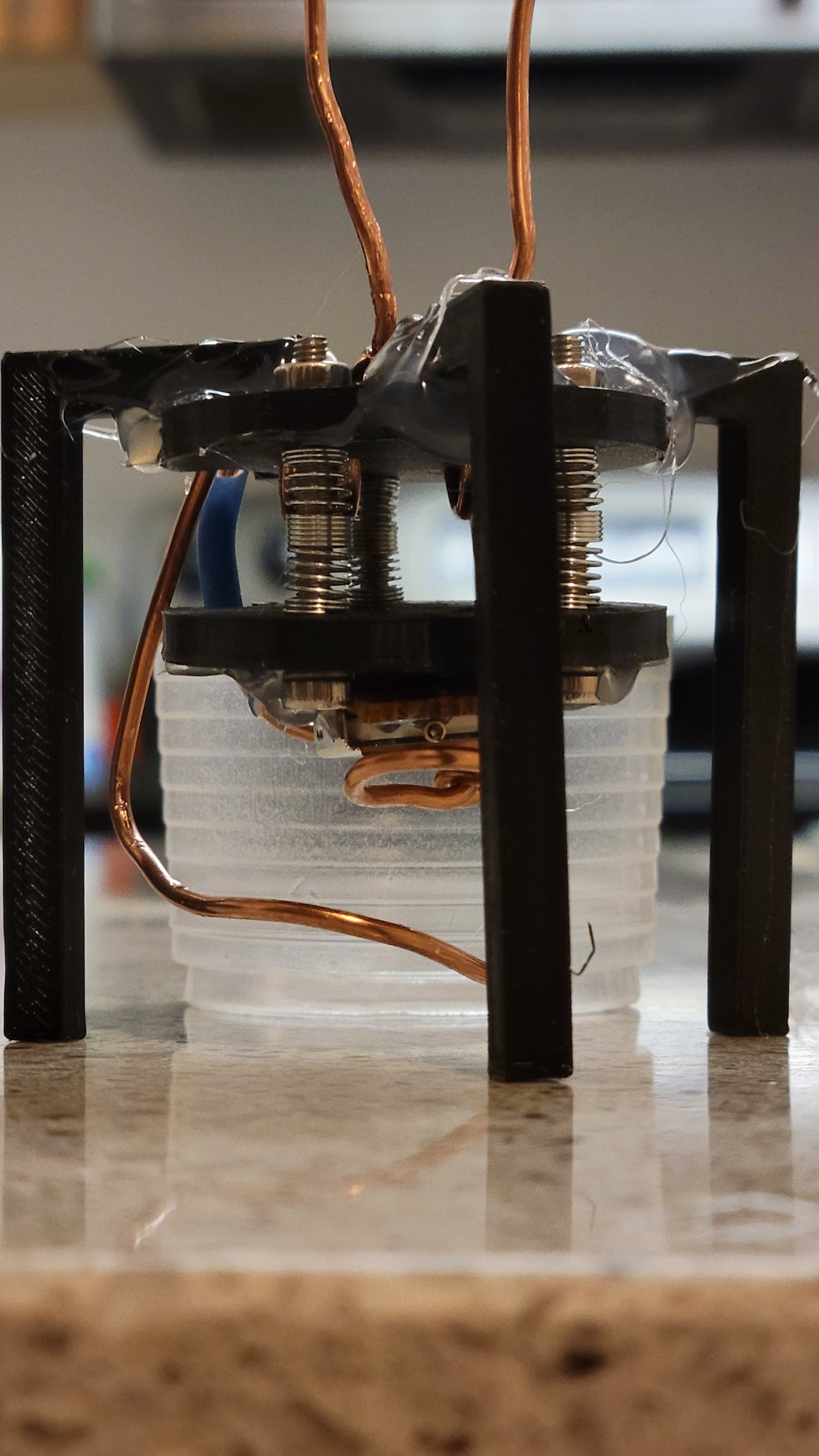
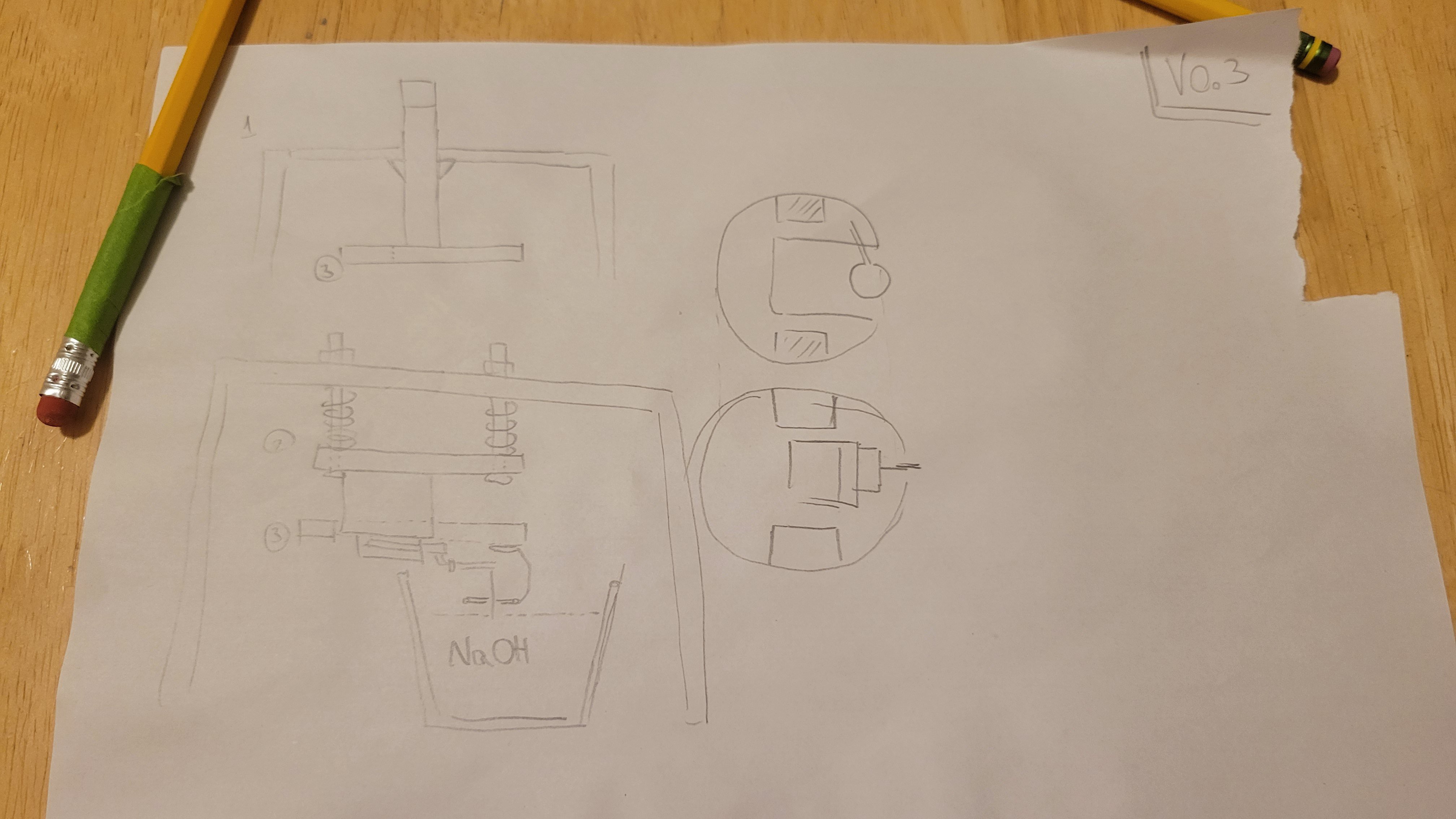
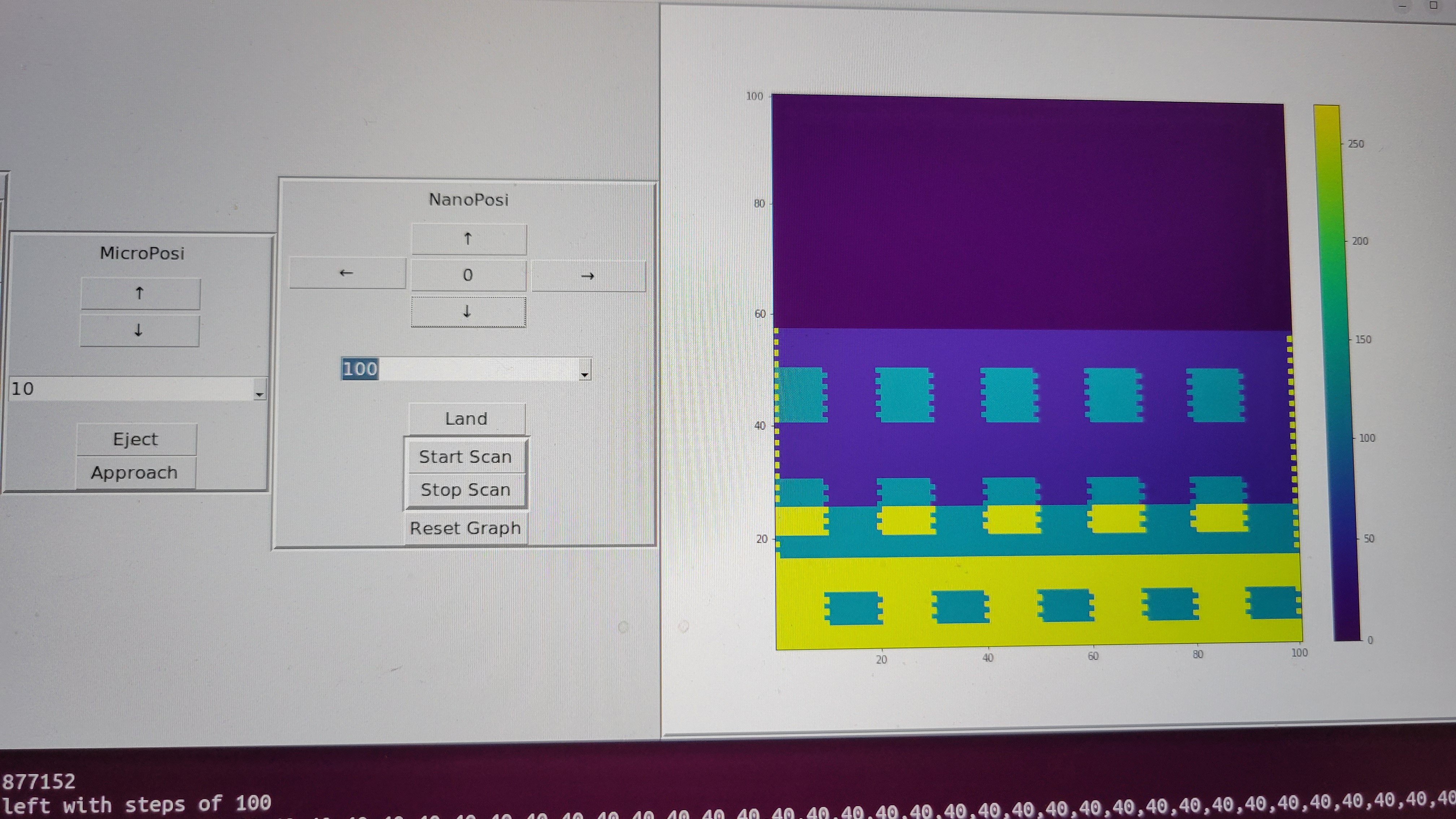
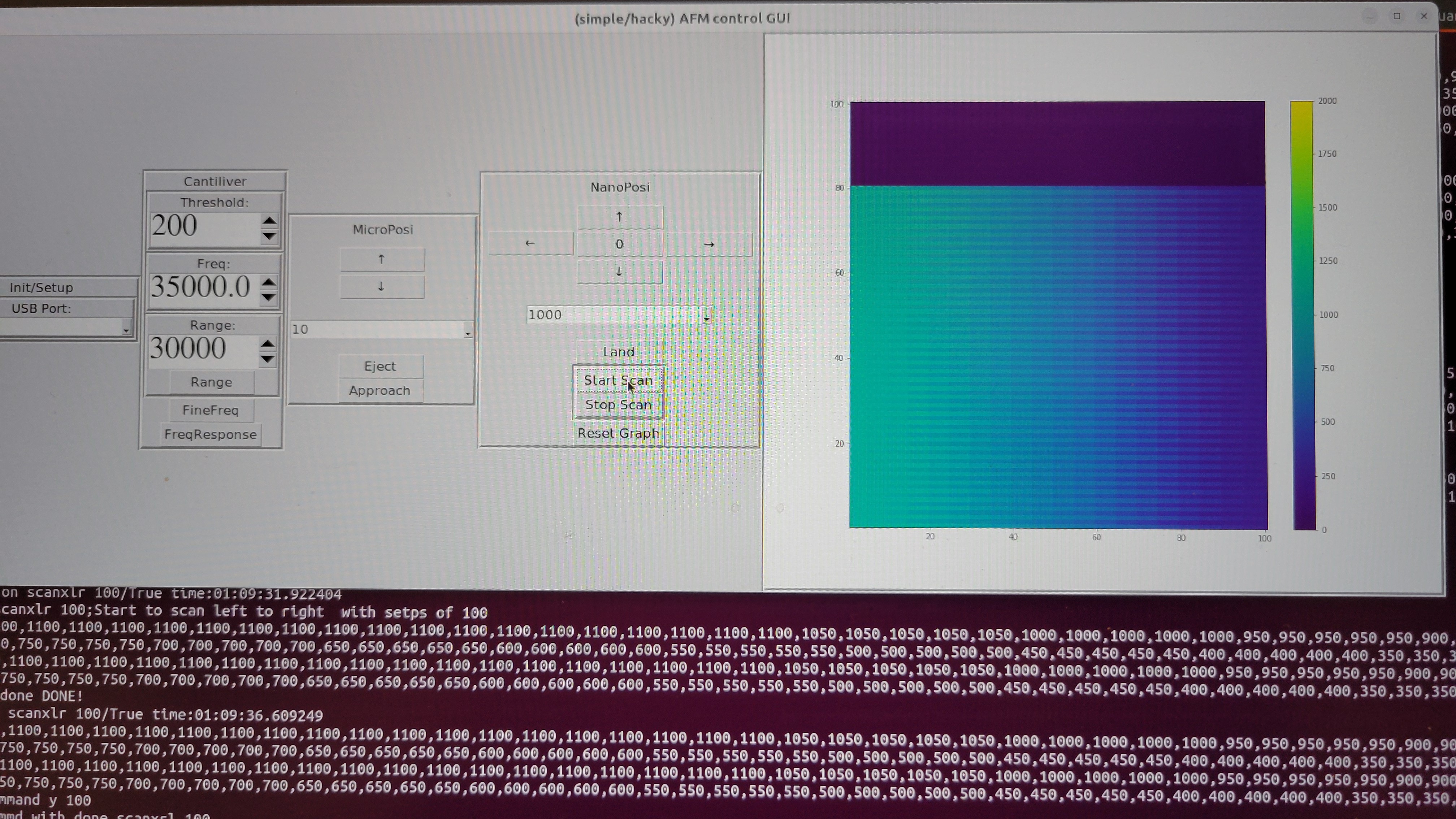
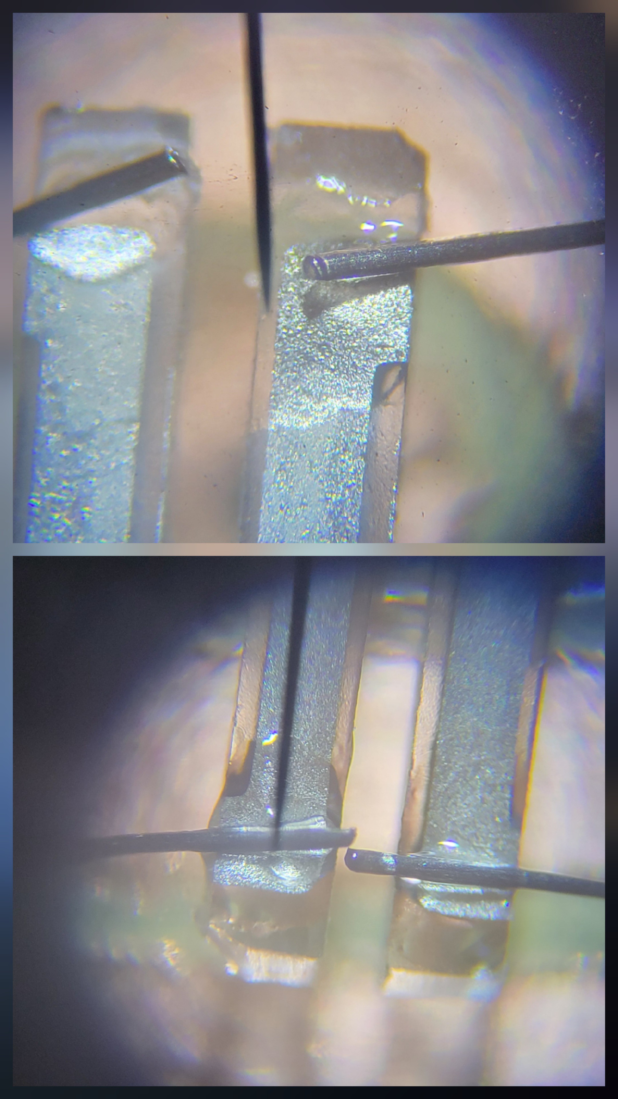
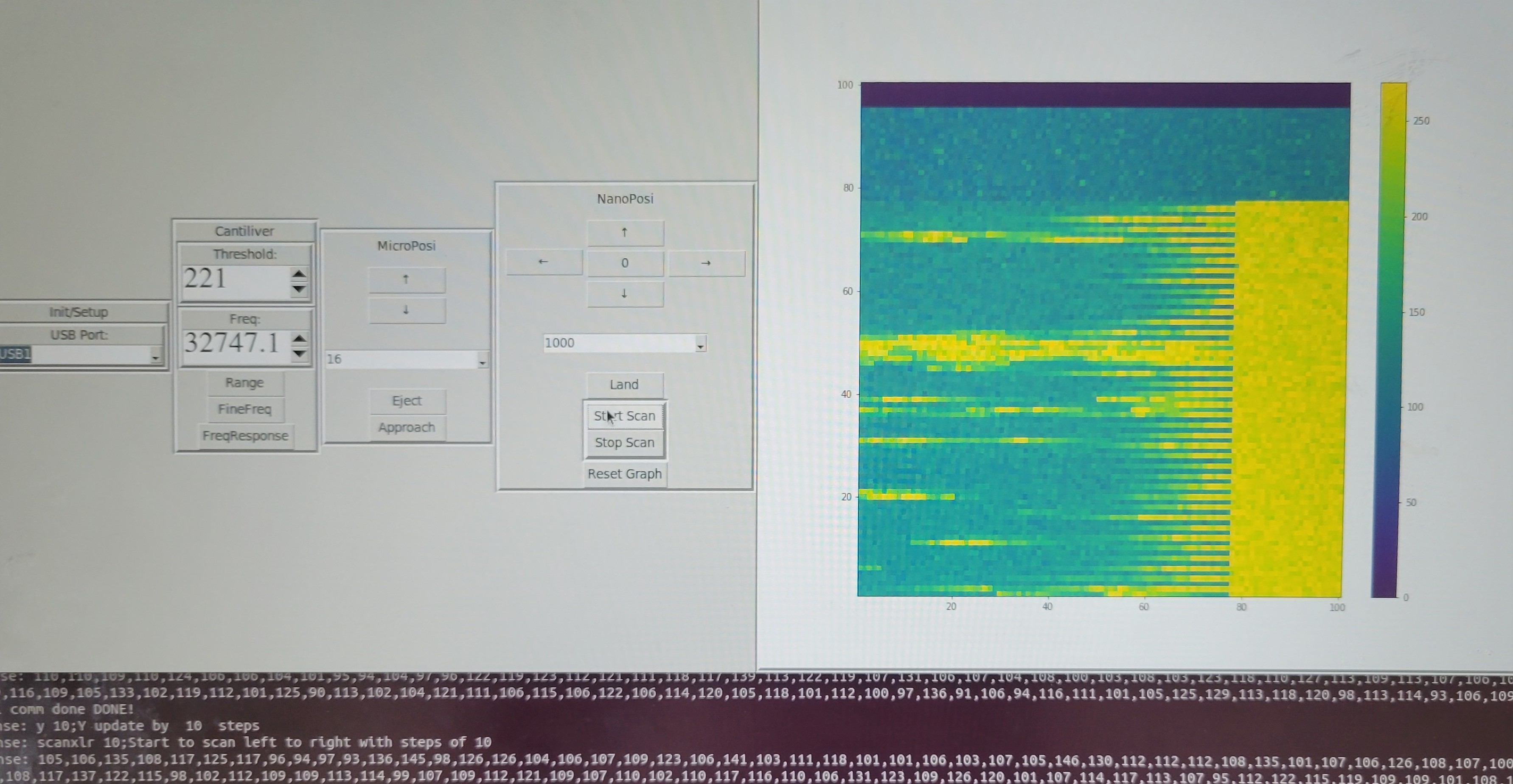
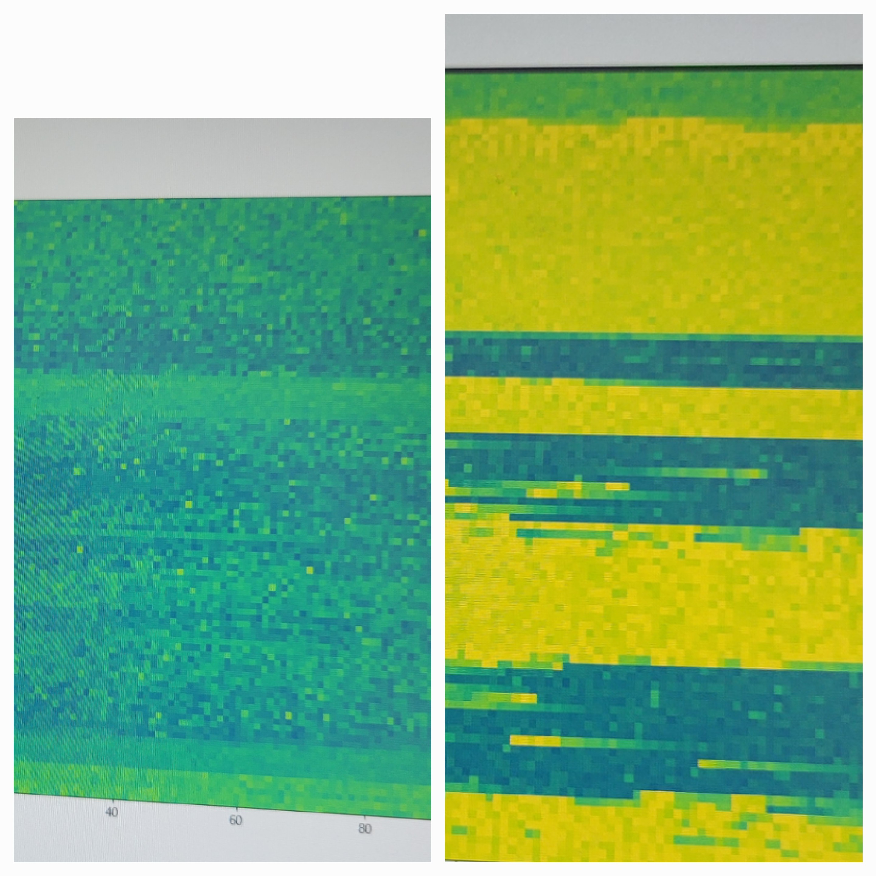
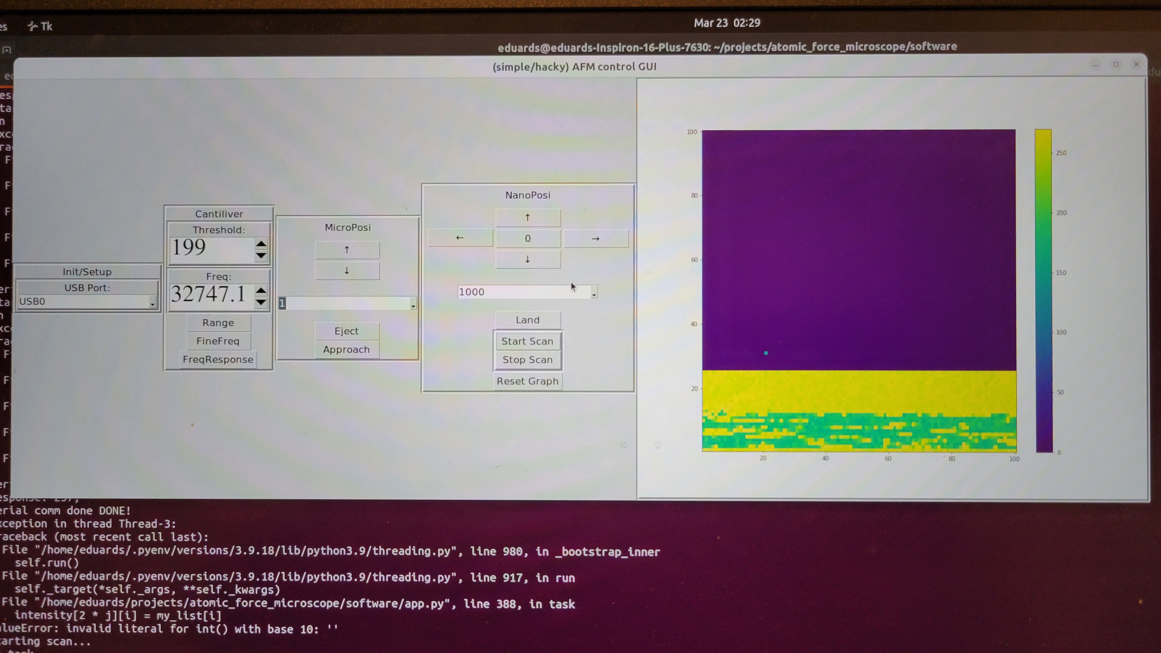
• Scanning Tunneling Microscope

    100dollarhacker11/05/2025 at 21:13 0 comments

    I had no intention to make STM, there are many who done it before and much better than me but I have to do it to debug AFM. Or at least to know that the patterns I see are really from CD-ROMs' pits. 

    I've used AD9833 signal generator at 0 frequency and played with phase to get voltage from zero to 0.6 Volts. There was no via there so I had to solder to capacitor. Ugly but working.

    This output will be connected to the surface. 

    On the other side probe will be connected to USB connector (it's not really usb, just a holder for AFM tip). Output from op-amp will be connected to internal Arduino ADC A3 pin(pin A5 is for I2C). If everything will work we could get image with minimal hardware change.

    Great news! I made the 'circuit' I've described earlier and it looks working. When I don't connect signal generator (AKA poor mans DAC) the reading gives something below 400. Readings are jumpy but it's alright simce I've not grounded everything there. When signal generator connected the readings are flat 1005 (I didn't investigate why this magic number but probably it my OpAmp getting into saturation). 

    Setting threshold to 500 could easily distinguish between touch and no touch. 

    I've connected wire to surface and make sharp tip from copper

     (Etched Tungsten is probably better but is so time consuming). 

    Started running 'approach' but everything stacked, just realized I've used A5 which is also used for I2C communication. Manual approach looks ok.

    Changing A5 to A3 solved the issue. I was able to 'approach' and made few linear scans. It looks much more stable than AFM scanning. 

    There is another problem now. That surface gets out of the reach of the tip for some reason. I will try to reduce vertical hop size.

    I've made some changes to vertical hop size, number of readings per sample (I have lots of noise and too lazy to build grounding enclosure) and changing threshold to 500. Now reading left to right and right to left seems stable. Now I should make an image. Hoping for the best.

    Now I made separate python file for STM controller, so I can make images in simple way. Here is what I got from my first run:

    I see clusters so this is a good sign. (The white stripes are places tip couldn't reach sample anymore since it's not aligned well with tips's motion plane, I had to move micropostioner to re-align)

    Another problem is that surface is not always align with tip movement. I've realized that the problem is that my mechanical system contains only three degrees of freedom XYZ. I need 5 degrees of freedom XYZ plus  Roll and Pitch. 

    Another interesting observation is that now there's changes in height of one samples. In AFM changes were always of few samples.

    It took me a while to find a way to connect Tungsten wire to copper (it doesn't like soldering) in simple way. 

    Now let's try it! Finger crossed 🤞 

  • Never settle

    100dollarhacker10/25/2025 at 14:56 0 comments

    Quality of images are not satisfactory in my opinion and I have no tools to debug it. So, I thought to take some detour and build STM (Scanning Tunneling Microscope). 

    Most of modules are same except the input one. It should be relatively 'easy' given the fact that I have most of the components like OP-AMPs and ADC.  Plus, there are nice schematics of STM online.

    I am pretty sure I could find what the issue is and once everything is OK, go back to AFM this time I will use laser based AFM cantilevers.

    The funny thing is that sensor module basically has OpAmp with 10 MegaOhm resistor feedback. This is a perfect for us only thing we need is ADC which we can use on Arduino or some standard 16bit ADC. 

    Another thing is, using signal generator as DAC. It's possible by setting frequency 0. Sine wave and changing phase.  

    Basically it means we can do STM, without hardware modifications. Just be reconnecting some wires. 

    Just checked now and both AD9833 and Arduino's internal ADC can work well. LOL! 🤣 

  • Sharper images

    100dollarhacker09/16/2025 at 12:59 0 comments

    I made modifications to software and was able to produce sharp cantilevers. Now let's try to make picture hopefully they will be sharp this time.

    Connected everything together and debugging 'Approach'.  (Algorithm that controls both micro and nano movement, which lets cantilever land safely on the surface)

    Glued the cantilever 

    Now it seems to give consistent reading for landing.

    Approach seems to be working now debugging new scanning algorithm.

    Fixed some issues with the scan now getting (smooth results [with 500 jumps])

    5500,5500,5500,6000,6000,6000,6000,6000,6000,6000,6000,6000,6000,6000,6000,6000,6500,5500,5500,5500,7000,6000,6000,6000,6000,6000,6500,6500,6500,6500,6500,5000,6500,6500,6500,6500,5500,5500,7000,5000,7000,5500,5500,5500,5000,6500,6000,6000,5000,5000,6500,5000,6000,6000,4500,4500,5000,5000,6500,5000,5000,6500,5000,6500,5500,5500,5000,5000,5000,5000,5000,6500,5000,6000,6000,6000,6000,5000,5000,5000,5000,6000,5000,6000,6000,6500,6500,5000,6500,4500,6500,5000,5000,6000,6000,6000,6000,5000,5000,5000,DONE!

    Running few test reading from left to right and from right to left gives roughly the same numbers, which is excellent! 

    I've added auto stop mechanism. If 'needle' has to go up/down too much it stops the program. It happens to me twice. Now I am not sure if this bug or my surface is not straight? (This is just a 3D printed plastic nobody insures it should be smooth in any way.)

    First image of new algorithm:

    I still haven't found the reason why I see this slope.  Maybe I need to let it cool down after approach.

    Note: This is done without sharp cantilever, as I am still learning how to use it and parameters for smooth approach. 

    I've made a fix to control steps size. Until now, I've used 10 steps hops. When, changed to 100 the results become more jumpy with ups and downs reaching 10,000 steps.

    6000,8500,6000,6000,5500,4000,3000,3000,5500,5500,6000,5000,3000,4500,6500,4000,4000,5000,5000,4000,4000,3000,2500,3500,3500,3500,3000,3000,2000,4500,3000,4000,3500,2000,2000,12000 

    On the other hand when set hop size of 1, terrain become flat (relatively to 10 hop steps).

    14000,14000,14000,15500,14000,14000,14000,15000,14000,14000,14000,14000,13000,13500,13500,13500,13500,15500,13000,12500,12500,13500,13500,13500,12500,13000,13500,13500,13500,13500,13500,13500,13500,13500,13000,13500,13500,13000,12500,13500,13500,13500,13500,13500,14000,14000,13500,14000,13500,14000,13500,13500,14000,14000,14000,14000,13500,14000,14000,14000,13500,13500,14500,14000,14000,14500,14500,14000,14500,14500,14000,14000,14500,14500,14500,14500,14000,14000,14500,14500,14500,14500,16000,14500,14500,14500,13500,13500,13000,14000,14500,14500,15500,14000,14500,14500,14000,14000,13500,14500

    Now it's time for last piece of the puzzle the sharp cantilever. I have only two of those since two were sent for SEM picture. Actually the quality is not bad of about 150nm. (I think it's pretty good for quartz fork+ Tungsten wire $5 price tag.)

    Important note: Loading the sample and cantilever is quite straightforward. First, I am pulling delta stage as low as possible put the sample on it.

    Then, I place the cantilever tip few millimeters away from the sample (using the screws). Once it done, run approach with steps of 10. It's fast enough (takes about five minutes) while safe enough not to brake the cantilever tip. (10 Delta stage sample roughly equals 10,000 nano positioner steps.)

    Then press 'start scan button'

    Got those image with hop length of 1

    And with hop length of 10:

    It looks like x-axis is not functional. 

    Just realized that this might be not electrical problem but a property of the Quartz Fork. I've observed in the past that oscillation takes time to start or fade away. To test this hypothesis I've added 500 millisecond to each X movement when scanning. And got this 

    Proving that X-axis is functioning if enough time is given.

    Now, it's...

    Read more »

  • Making sharp cantilever

    100dollarhacker04/30/2025 at 01:37 0 comments

    EDIT: Tl;dr skip to the last part, there is a working method 

    Last images I did are not sharp. I was not able to make qPlus tips but using very thin wire of 0.05mm. The problem with 0.05mm wire is that I was not able to etch it to make very thin cone instead I just cut it with scissors and hoped for the best. The 'best' was blurry images. 

    I've re-read articles about making sharp tips one of the ideas was to add wire on the other side also to counter weight. 

    Indiana Jones counter weight type.... (Sorry no GIFs here) 

    So I started with making mechanism to be able to etch Tungsten wire very close to fork's edge. This is the schematic/idea

    And this is what I made...

    Well, it's not as perfect as I wanted it to be but  it will do as a first prototype.

    Ok, this prototype was not good enough. To get sanple I had to bend thick copper wires. In the process the loop was not aligned with horizon as a result all the bubbles would pop few seconds after they formed. 

    Another thing was the line of sight I couldn't easily see the length of the result wire. In the end I made tips of 1mm length which was not bad for begining but now I need something much smaller to keep high Q factor for my quartz fork. 

    And most annoying thing that both tips were broken I don't know if I just clumsy or super glue was destroyed by concentrated alkaline.

    So, I went back to drawing board and redesign something which will solve all those problems and keep my fingers away from this material as it takes ten minutes to remove it from me. 

    New design (ver 0.3)

    Will make components bigger to make my life easier 

    Another prototype, although still not perfect it much better. 

    Now let's try to make sharp tips... 

    Another change was software both upper layer (written in Python) and lower layer (C on Arduino). In upper level I change the way components communicate, now all the commands to serial are going through queue. This way we can scan and control up/down. It's important when we want to make corrections in real time.

    (By the way, it's not real image just a demo mode for faster development)

    On the lower level I change the way, how we trace height. Previously the Z component was predetermined and we only checked the response from surface. It caused problems as surface is not flat usually. Now I am tracing the surface to some extent.

    Now we can see a huge difference between previous with 2-3 colors to what we have now 

    (Again it's not real image it demo surface)

    Another upgrade was serial communication. I've used one that was way to wasteful for poor Arduino Uno. I made something simple by myself as my comm. are very limited in structure. (Command name and one parameter). 

    Now communication running much smoother.

    Ok, back to making sharp tips... I've decapped six quarts forks, three 8x3mm and three 6x2. Using microscope I've glued Tungsten wire 6mm once the glue was broken once I've moved it. Once 8mm broke as I touched it. So Ive left with two 8mm. One I was able to etch, and dropped from 1cm which made it glue break. The other once broke as the copper loop felt from it's place. 

    The main problem now is that it takes so much time to glue each Tungsten wire, plus, it takes 24 hours for glue to fully cure. 

    Now I've tried to glue with magnifying glass of soldering station. Although magnification is only x3 it was still possible to glue quite easily and there was almost no restriction on how many I can do in parallel 

    Although I used to much glue, the method works really fine. Now, when process is cheap and fast I can do many hopefully some will be successful I need only few.

    Run another bunch with four quartz forks

    When looking under the microscope you can see issues 

    So some of quartz fork irreversible, except this it works really good. Although quality is worse it will be smoothed out be quantity.

    Another...

    Read more »

  • More images

    100dollarhacker03/25/2025 at 01:56 0 comments

    Let's start with an image of nothing.

    Just a white noise...

    Now, I managed to calibrate it better and run on the same surface to see if it gave me same (give or take) image.

    My raster scan is not perfect as you can see this comb shape image.

    Another problem I've noticed is that images are quite binary it each not touching (and getting 100-150) the surface or it does and goes to 240-250.

    The yellow color is where fork touches something the blue/green is where nothing detected.

    Contrast is another issue, it took me lots of trials to get a better contrast:

    Last but not least is that I don't know what I see. I have only one sample of CD-RW surface which I have ripped off. Some places have information and others don't. I don't really have control over where I land in this nano world. 

    Some claims to see atoms with STM, using similar piezoelectric discs, those structures are sub nano. Red laser, CD RW has 0.8micro size grooves and 1.6micro spaces between them. 

    So, I've tried to change step sizes from 10 to 100. Still I don't seen the groves although I see some forms and they repeat until I restart the setup. 

    I feel like this joke: the surgery was successful the patient died. 

    I got working machine but the magnification so powerful I don't even know what to expect.

  • Building GUI

    100dollarhacker03/21/2025 at 11:28 0 comments

    Python is really amazing language you can build complex software in few lines of code. 

    I made very simple/hacky GUI, it has the minimum required to get 2D data. 

    It has few stages, connecting to serial port. Calibration of cantilever frequency. Micropositioner control, nanopositioner control and 2D heatmap graph to show output.

    It took me more  time than I've expected to connect GUI to firmware but it works now. 

    I have only CD-RW as a sample. If someone knows other nano scale structure that I can put under AFM, let me know. ( And it should not cost fortune...)  

    Fixed the GUI issues I had now it's working (although with some bugs) as expected 

  • First image

    100dollarhacker02/27/2025 at 06:54 0 comments

    After long, long work and long, long calibration I got my first image of copper plate. 

    The graph is reversed, since in my setup when we get 250 it means tip didn't touch the surface 

    Funny thing I found is LibreOffice and Google Sheets doesn't have 3D plots. So I had to find some simple python code to do it. 

    ------------------------------------------------------

    Manual calibration is difficult since each touch takes all system out of stable state. 

    So, I've moved back to OpenFlexture with stepper motor which can be controlled by software. 

    Luckily we don't need any electrical changes 

    Looks good:

    I've finally figured out how automated calibration should be performed. Move micropositioner up one step go from down to up on nanopositioner if found stop otherwise go down in nanopositioner and make another step in micropositioner. At some point tip should toch the surface.

    After some thought I've decided to add another power source for power hungry stepper motor. Although it possible to use original power board the voltage regulator became too hot and at this point I didn't want to lose another board. USB-C PD (power delivery) is an easy way to connect USB-C adapter and get its power. 

    It's small and can get you voltages from 5 to 20v depending on what your adapter provides. 

    ----------------------------------------------------------------

    I've tested the stepper motor with microscope and saw that on micro meter level it moves much smoother than when I touch it with my fingers. 

    ----------------------------------------------------------------

    I was amazed from magnetic eddie current dumping system, plus using a tire and box of rocks was not convenient (although cheap) to work with. So, I've started to build a box to hold springs. Instead of 3D printing I've just used big acrylic board and made holes in it. Printing such big components will take forever in my 3D printer. 

    I know, I know this tool is prehistoric but it did its job without cracking anything ( It's my first time with acrylic so prefered to go slow... very slooooow)

    ------------------------------------------------------------------

    I've added new commands to control micro positioner/stepper motor from software.  Plus, I've added 'ring' command it to test piezoelectric discs connection. Although it's volume is low and nothing should be on piezoelectric discs it makes a noise and you can give a channel number {1,2,4,8}. This way you don't need signal generator.

    ------------------------------------------------------------------

    Added magnets and copper plate on top. This way we have Eddie currents that takes energy out of the system.

    You can see that I've pushed them to the same starting position. The one with magnets stops very fast the other takes few seconds 

    And this is how upgraded mechanical part looks like 

    -------------------------------------------------------------------

    The micropositioner stepper motor worked better than I thought. I was able to run with 10 steps and even 1 step at a time to make 'approach', step that was super annoying to do manually.  The accuracy is amazing I was running with 10 step hops it was so small I could not see the change only after a while I could see. ( I was looking through my cheap but long distance microscope). 

    Interesting thing I found is if I run small hops (less than 16 steps at a time) micropositioner goes back a little. This is not happening if 16 or 32 steps at a time used. 

    When this happens it usually takes 3 steps to get back to a point it's touching the surface.

    Now what is really amazing is it takes about 10,000 nano-positioner steps to get back those 3 micropositioner steps. Each micropositioner steps is about 5 degrees devided by 64 (from stepper motor specs). 

    I finally solved the creep issue, after learning more about phenomenon I've found...

    Read more »

  • Data acquisition

    100dollarhacker12/24/2024 at 22:55 0 comments

    All the work comes down to this moment, data acquisition. The idea is to get data representing the height of tip as a function of x,y. 

    Unfortunately, it's not consistent. I go up and down 2000 steps and I see frequency change. I would expect frequency to change at certain height give or take some noise. Well, I see something similar and the noise is of about 200 steps. Than comes the trouble, if I continue doing it say four five times, the threshold frequency changes qnd goes up. Tried with tip and just clean quartz fork. Added tire to remove vibration and turn off all electrical appliances around. Still same result.

    I suspect it's the rubber bands in 3D-printed xyz stage.

    I've ordered cheap Z-stage on aliexpress.  https://www.aliexpress.com/item/3256806481789030.html?src=google

    Got this beauty 

    This beauty is really small, so I need to rebuild all the 3D mechanics again for this miniature size. It will be third time I 3D-print this part... 🤕

    I really fed up from this project, instead of printing I've just place hard metallic piece. It's ugly hack but hey that's my name 😉

    Let's see if the creep comes from all the plastic or 3D printed Delta stage.

    Still got the creep, now trying different types of quartz forks, maybe it's because of soft metal the quartz fork connected to the tiny PCB board. 

    Basically it's same fork now glued to PCB. Other option is one of the fork's prong glued to the tiny PCB. Fingers crossed...

    'qSensor' didn't work, one I couldn't find frequency other I could see barely something. 

    The regular with base glued to PCB one didn't work for some reason ( maybe it got bit of glue on it) other was working and I could find the base frequency. Then I managed to break it. 

    Ok, made another three quart forks (just to be prepared if anything breaks). Made a few tests, still have the same problem. 

    It's not the xyz stage, it's not quartz fork (now it's rock solid). What else could it be?

    It's not USB connection used little piece of PCB to make it stable. It's not electronic problem rechecked with scope.

    What can it be? I have no idea... 😧 

    Ok, after reading some papers and specs of piezoelectric materials it looks like even the expensive ones have some creep (about 10%) and hysteresis. Moreover, it changes with time... 

    So I wrote simple piece of code which basically goes up until passes some threshold and then goes down the trick was to make it slow so piezoelectric element will get stable. 

    Ta-da first time data...

    It stable enough for now with 400 steps diff. I will remind that those readings were done in noisy environment, without vibration dumping and without shielding. 

    Another setback, although I can achieve precision of 400 steps. It's changing with time, in other words if I do two tests one after another I get close results, but of I take a long break between I got results not even close. 

    I suspect that this is mechanical, as I've applied too much glue to hold the electric wires when connected piezoelectric elements. Plus used regular electric wire instead of one thin wire

     I will try with using tiny wires and soldering paste and see if it's the problem 

    Made another mechanical part version 4.0 I think. 

    For now I have used AliExpress micro positioner, only because it's smaller and easy to obtain. I should go back to OpenFlexture Delta stage, since it more accurate ( I think, don't know how to measure it) and can be easily motorized. 

    Used old piezoelectric discs to try to learn soldering. It turns out brass part is easy to solder to quartz almost impossible without ruining it. 

    So I will use conducting ink(scribepen)+super glue to connect 0.3mm wires. 

    The result was quite good and even my kids were unable to break it. Let's connect the real one and hope for the best. 

    Started adding thin wires (ground)...

    Read more »

  • From DIY to 'turnkey' project

    100dollarhacker11/12/2024 at 05:26 0 comments

    TL;DR - 

    Now you can buy all electroincs of this project (boards with components assembled) just by two clicks on PCBWay. No prior knowledge of electronics required. Plus, you can buy all the bodyworks using 3D-printing services. All is left is some gluing and some minimal soldering that everyone can do. 


    The longer version - 

    The idea is that this project will be accessible to all, not only electronics hobbiest. One of the problem with is that this project has lots of electronics. I was wondering, how someone without  soldering skills (no, it's not easy as it looks like) and good electronic knowledge could make this project?

    In perfect timing (burned most of components by applying wrong voltage) I've been contatcted by a guy from PCBWay who was willing to support the project for a honest review. [Oh well, now I'm biased 😜]

    It turns out that PCBWay and other comapnies are providing something that called PCBA. Which stands for PCB Assembly. Wait! What?! It's fantastic I could provide my schematics/boards and people could get assembled board with all the components. 

    So, I wasn't laizy and checked other companies all had the same answer put the files here (some demanded to convert to some bizzare formats) and engineer will return to you. Big NO,NO! I want people to push the button and get those boards. 

    I've used OSH Park, they have realy nice sharing option and it's supper easy to buy boards from them but they only provide PCBs.

    For example, JLCPCB provide something close to that, you need to provide project files, BOM file and CPL file, then it goes through process of choosing components. In my case it chosen non-standard components and price was dobuled (plus fee of $3 on each non standatd component). After going each component and choosing the basic one price dropped to something reasonable. After that it took me to other window where components were placed for some reason all my ICs were in wrong orientation. So that had to be fixed. The price was the same as PCBWay give or take 10% (but it provides you two assemled boards). I've tried to ask if only one board could be provided but nope. For seasoned hardware developer it could be a good solution but if I want to share it with people who just want to build AFM with minimal electric knowledge it just not an option.

    This is the point where I got realy amazed by PCBWay [Maybe I'm bit biased here] they DO have a posiblity of sharing the project, with all components. 

    To show how things may go easily bad was my experience with OSH Park. I got QFM board shared project in OSH Park, but they provided only the PCB (no assembly) and I failed to solder all the components properly (yeah, took me a week to realize that) and they don't provide the full schematic before you buy. I ended up building my own PCB layout just to make it work.

    Biased? Maybe, but until now couldn't find any other service that provided PCB and component assembly which could be easily shared.  

    We can conclude it with the following: You got mainly three options.

    • Mill PCBs and assembly by yourself [fast]
    • Buy PCBs and assembly by yourself [cheap]
    • Use PCBA services (such as PCBWay) to do it for you. [easy]

    Now, lets look at the solution in terms of time and money.

    Milling yourself is the fastest (and cheapest) but you have to own CNC machine and the knowledge to make PCBs. (It can be quite tricky). So timewise it will take you few minutes to build PCB board and few hours to assembly if you have good soldering station (plus good hands) and knowledge to solder 0.5mm pitch (distance between each leg of the integrated circuit) components. 

    Buying PCBs can save you the hussle of building ones but it takes about 2-3 weeks to get to you (unless you pay much more for expedit shipment, then it will take only 7-10 days). You still need a good soldering station (I use hot air gun and tiny tip iron) with magnifier...

    Read more »

  • Final tests

    100dollarhacker09/24/2024 at 18:07 0 comments

    I've added new electronics and better mechanics. Now it's easier to position probe as I like and I can easily change probes (no soldering needed).

    Probe #1

    I got it non simetrical for some reason (mainly because it's hand made and not CNC). but it's WORKING! You probably ask yourself why it's important, well because I was afraid that longer lines will add resistance and stray capacitance which will kill oscillation (like in clocks) but it didn't. It works fine! Now it's time for more compex probes.

    Probe #2 - quartz fork without the case

    I know we already tested it, but I prefer to go slowly but surely. 

    We can see that it's stable without the quartz fork encapsulation.  

    Sanity check done ✅ 

    Let's start more compex probe designs.

    Probe #3 - Quartz fork with Tungsteen wire (sharpened by NaOH)

    If already wrote about how to create supper sharp Tungsteen wires (this project logo :) ) but once I glue it problem begins. If there is too much glue on the fork's prong it kill oscilation. If too little it doesn't hold the Tunsgesteen wire properly. Glue plus wire kills oscilation sometimes only the glus's weight kill oscilation. like in thie case

    Probe #4 - One of the prongs connected to the base. 

    Couldn't find the frequency. Well I've found it but it was too high I am not sure if it's the main or side lobes.

    Probe #5 - I was totally clueless of how to continue. 

    Then I recalled that I own really thin Tungsten wire, of 0.012mm wide. It's so thin it breaks easily in your hands. But now I got more experience and nothing to lose. I managed to push some wire into syringe. Since it was so tiny I thought to use 0.1mm wire to paste the glue (instead of toothpick). 

    The glue was strong enough but I had another problem. Since the wire was so short I couldn't etch it. Luckily (yeah, I feel lucky today) I managed to cut it with scissors. (It's impossible to do that with 0.1mm wire, it breaks the glue) 

    Now I've tried to scan the frequency and TA-DA! I got stable frequency 

    Now it's time to lower the probe and see if it successful and we got AFM or all this project goes to garbage. 

    Stay tuned 😉 

    P.S.

    I found fundamental design flaw in my design. I've noticed that sometimes the difference I got is near zero and sometimes near maximum of 5k. 

    The reason is that quartz fork is oscillator with its frequency and phase.

    That's why sometimes I get no signal, it depends on the phase between input and output of quartz fork. There are many ways to solve it but for now I will just restart the system and hope for the best.

    After some rethinking, it looks like we have software solutions. AD9833 is able to change it's frequency programmatically. So we can start normally look for high and low. If not successful, change phase by 90° and try again. Once right frequency found try to get better results changing phase, until looked.

    Update:

    Started another test, failed as the usb metallic cover was on the way. Few power moves the pliers and it ok. 

    Now we had some issues with frequency. I didn't had mechanisms to set frequency. Now I do. Continuing to the test of soft landing this time with real (not yet sharp) Tungsten probe. 

    Update II: 

    Was able to do first measurement with Tungsten wire. 

    The procedure is run 'range' which runs coarse frequency change of 1Hz and range of 200. This finds the frequency where maximal/minimal eclipse occurs. 

    Now we set new base frequency by 'bf' and run 'land' function steps of 100 (I ran with 1000 and crashed into sample). If fails to land change high of micro meter movement (open flexture Delta stage). 

    Update III: 

    Added 'ph'ase function which changes current phase. It helped to change convolution result from ~120 to nice ~ 30. No matter what I did I couldn't go below 30. 

    Going step by step, I thought it would be a good...

    Read more »