Neil K. Sheridan
-
Testing of ElephantAI
10/19/2017 at 20:18 • 0 commentsSo, at this stage we have built, tested, and setup, all the computational components of the system, including their associated circuits, and we have added our final code to each of them!
Remember we have three primary computational components:
-- Elephant Detection Device
which is comprised of:
dayPi (Raspberry Pi)
nightPi (Raspberry Pi)
-- Elephant Deter Device
which is comprised of:
PiZero
AmpZero
Now let's get started on testing how the system interacts!
For testing, I suggest having a monitor and keyboard/mouse for each of the three primary computational components. And of course, we want all of our associated circuits setup! You don't need the solar recharging circuit. You can just test the IR illumination devices by connecting a 12v battery to the optically isolated switching circuit.
Let's see how we get on!
-
#buildinstructions for hardware: an optically isolated circuit for IR illuminator
10/16/2017 at 19:48 • 0 commentsHere we are going to make a circuit to isolate the 12v IR illumination devices from the 5v raspberry pi! We need to switch them on using GPIO out from the pi, but we don't want to expose our raspberry pi to any risk of it getting 12 volts!
Now, this circuit will be quite tricky if you are not used to working with its two main electronic components: a transistor and an optocoupler/optoisolator!
Let's first investigate what these are:
WHAT IS A TRANSISTOR AND HOW DOES IT WORK?
Now, in our circuit we want to turn on the IR illumination device. We could do this with a push-button switch! But computers can't push switches! Well, we could make a robotic hand to push the switch I suppose, but that would be a bit much! So we use transistors in order to enable computers to 'push' switches!
![]()
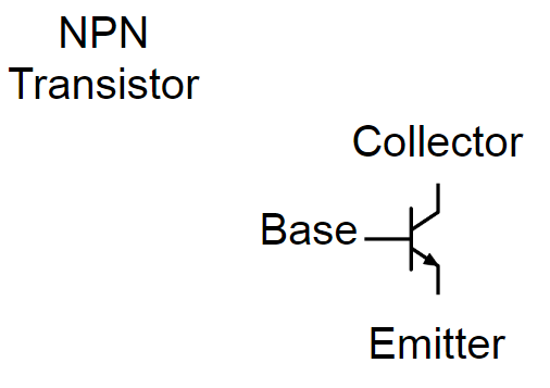
See it does look a bit switch like doesn't it! There are different types of transistors, but we are using a bipolar junction transistor (BJT) There are two different structures for these bipolar junction transistors: NPN and PNP. The structure is the type of semiconducting materials the transistor uses. You can read more about these here: https://en.wikipedia.org/wiki/Bipolar_junction_transistor#NPN
Anyway, all we need to be concerned about is that we can switch the transistor on or off by altering the voltage applied to the base. If we apply a voltage to the base, then current will flow between the collector and the emitter - so switching our circuit on! If we don't apply a voltage to the base, then no significant current will flow from collector to emitter - and our circuit will be switched off!
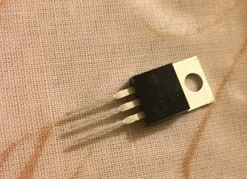
So, as you can see below, there are four pins on the (BJT) transistor I'm using:
![]()
1. BASE
2. COLLECTOR
3. EMITTER
4. COLLECTOR (the top one)
* the datasheet should explain which pin is number 1!
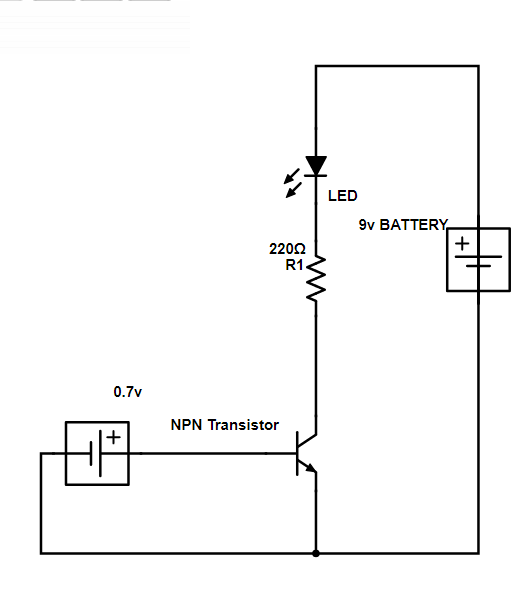
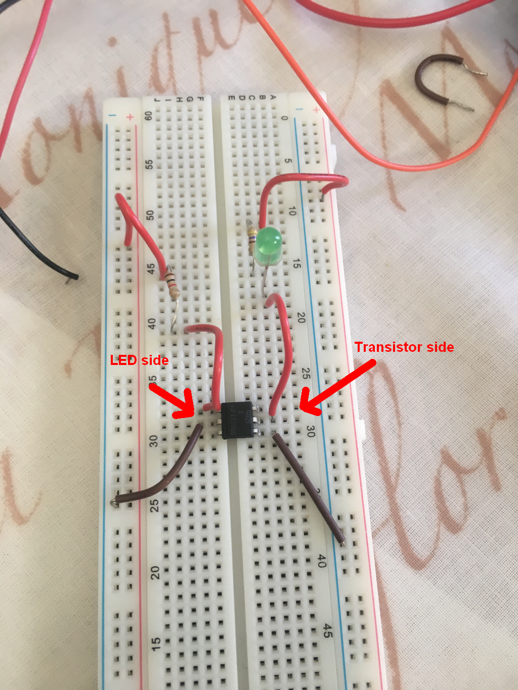
Now we'll build a test circuit using batteries. Here's a simple test circuit we can setup using a breadboard, one resistor, an LED, a 9v battery, a smaller battery, and our BJT (NPN):
![]()
So, you should have a good idea of how a BJT functions now! Below you can see my circuit in action. Note there are two batteries: one for the LED circuit, and one to send voltage to the base pin on the transistor. In this video, there's also a resistor between the battery (which is 6v rather than 0.7v) and the transistor base pin:
WHAT IS AN OPTOISOLATOR AND HOW DOES IT WORK?
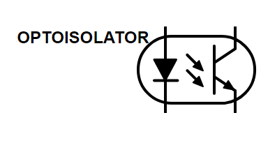
An optocoupler, or optoisolater, is a component that can allow two circuits to communicate with each other light instead of electrical signals. So the circuits are completely isolated electrically, communicating only via light. In the same way as our synapses electrically isolate our neurons from each other, communicating only with chemicals. The optocoupler uses semiconducting materials and LEDs to perform this function.
![]()
As you can see in the above schematic - it is basically an LED and a transistor. The LED on the left side is acting on the base of the transistor (on the right side).
So in an optoisolator we have pin arrangement of:
1. Anode for the LED (+ve)
2. Cathode for the LED (-ve)
3. Emitter for transistor
4. Collector for transistor
Well, that's if it is 4 pin. Many are 6 pin, so we might have:
1. Anode for the LED (+ve)
2. Cathode for the LED (-ve)
4. Emitter for transistor
5. Collector for transistor
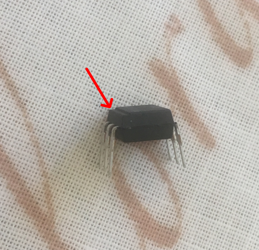
I have a 6 pin. The 4N25X. Datasheet: http://www.farnell.com/datasheets/90919.pdf
If you look at the datasheet you can also find out which side is for the LED, and so which is pin 1! In my case it had a notch on the LED side (see image below). It's very important to check your datasheet - it's not a good idea to just muddle through by connecting things and seeing if it works!
![]()
Ok, so we got the idea of an optoisolator! In our scenario, we use it because we don't want the 12v IR illumination device in electrical contact with the raspberry pi (5v)! Of course, you can isolate even DC and AC circuits with these too!
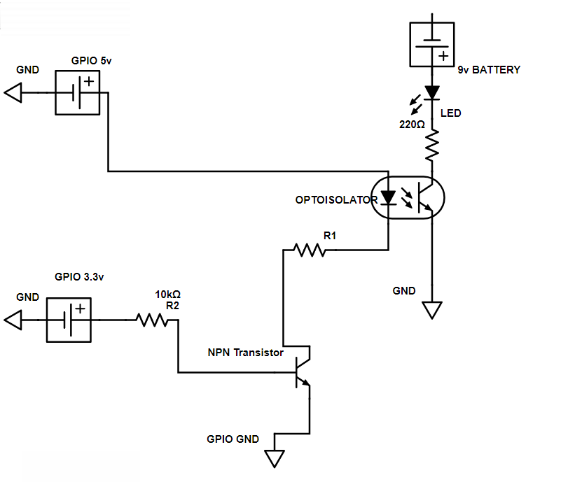
Right, so let's set up two circuits and optically isolated them with an optocoupler now! We will also use our BJT to switch the optically isolated circuit (with the LED) on and off from the Raspberry Pi GPIO with 3.3v!
![]()
So here we have the pi send 5v to the anode of the optoisolator, and we have a transistor that only allows this circuit to complete if the pi sends 3.3v to the base of the NPN transistor. On the other circuit we have a 9v battery and an LED. The 9v circuit on right can only complete if the circuit on left completes (i.e. we send a voltage to the LED on the optoisolater) In this case, the optoisolator allows current to flow between the collector and emitter so we have completed the circuit on the right!
Let's go through setting it up in detail:
-- First using the optioisolator. We connected our raspberry pi side of the circuit to pins 1 and pins 2 on the LED side of the optoisolator. Remember these are in the case of the 4N25X, corresponding to the anode and cathode for the LED. Then for the isolated circuit, which will hold our IR illumination device in the end (now it has an LED), we connected to pins 4 and 5 of the transistor side of the optoisolator. These correspond to 5 for collector, and 4 for emitter.
![]()
-- So first, we'll just test this out! We will not add the raspberry pi inputs at this test stage, but instead using a battery to supply voltage to LED side of the optoisolator, thus switching on the other circuit! You'll need to calculate what resistor to use depending on the battery you used for the LED side of the optoisolator. Here we can see it working:
-- Now we know the optoisolator works ok. And I think building the circuits in increments like this will help with any troubleshooting, and help with understanding them better!
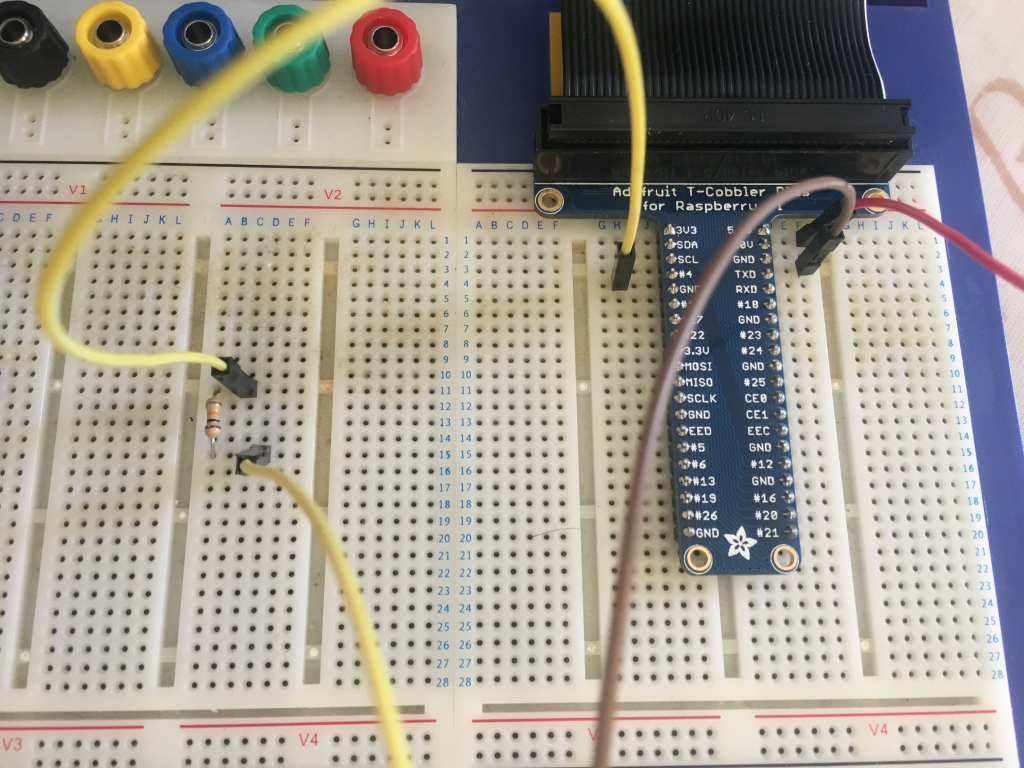
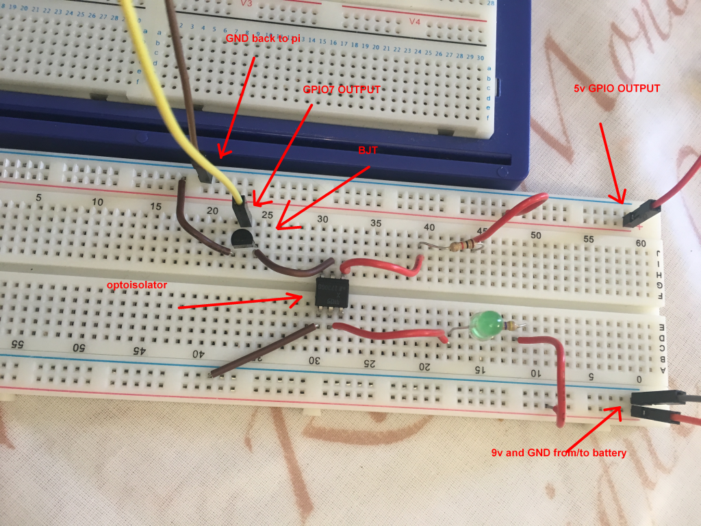
-- Let's swap that battery on the LED side of the optoisolator for the raspberry pi inputs and outputs. So we are sending the output from raspberry pi GPIO 7 (BOARD numbering) which is 3.3v, and we are sending the 5v from GPIO 2, and we are returning to GND which is GPIO 6 on the raspberry pi.
![]()
So you can see the GPIO 7 goes to a resistor. That's the 10k Ohm resistor in the circuit diagram above. After that, GPIO 7 goes to the base on the BJT (which I've got on the breadboard shown in image below).
![]()
-- Ok, so we are all set to write some code now! And send a voltage from GPIO 7 to the BJT, turning on the LED in the optoisolator, and thus allowing the optically isolated circuit with the green LED to complete! Remember the green LED will be our IR illumination device finally.
import RPi.GPIO as GPIO
import time
GPIO.setmode(GPIO.BOARD)
#GPIO numbering as board
GPIO.setup(7, GPIO.OUT)
#setup 7 for output
GPIO.ouput(7, 1)
# output from 7 is HIGH i.e. 3.3v
print("PIN 7 is output HIGH")
time.sleep(5)
GPIO.output(7, 0)
# output from 7 is LOW i.e. 0v
print("PIN 7 is output LOW")
GPIO.cleanup()
# cleanup
-- Now, let's run it and see what happens! Hopefully the green LED will light up when PIN 7 is high and go off when it is LOW!
-- Great! Well now you should know what is going on, and be all set to connect the IR illumination device instead of the green LED!
Don't forget that you might need different resistors that I did! You can find out how to calculate the resistor you need using Ohm's Law. There are many tutorials if you don't know e.g. http://hades.mech.northwestern.edu/index.php/Resistors_(Ohm's_Law),_Capacitors,_and_Inductors
FINAL CIRCUIT
Well, the final circuit we need to switch on the IR illumination device is quite similar to the above! We replace the 9v battery with a 12v lead acid battery, and the LED is replaced by the IR illumination device! We also alter our resistors! Don't use the 220 Ohm with the 12v IR illumination device!
[show it here]
-
Elephant Detection Devices: software overview
10/15/2017 at 20:57 • 0 commentsLet's do the example for dayPi
* main while loop is for the safe shutdown button, but I'm not sure it is worth the risk of using this.
So our while loops are going to be:
1. while light_sensor == True
The dayPi will operate whilst it is daylight according to the light sensor. So we use our def of check_light_sensor to get back HIGH or LOW from the light sensor. If this while loop breaks, we run our client code to become a client and send a message to the nightPi that it is time to start. Then we switch to server and wait for messages back. The messages are either regarding the light_sensor or a detection message which we must pass to our serial modem for sending out as SMS. Note that we continue to act as server until the light_sensor is True.
2. while PIR == HIGH
If the PIR sensor is HIGH, i.e. something hot is in range of the PIR, we need to perform our image capture, and then send the image to the elephant detector software
- take image
- send image to detector
if image == elephant:
- are we doing a deter? If yes, then we start the following while loop:
- run our client code to use Bluetooth to send message to deter device. Once we get echo back from deter device that message is sent, we run our server code and wait for deter device to message us when deter performed
- if that failed we try again for n attempts
- if we get deter performed message back we break out of while loop
- take data from detector and convert it to string containing top 5 elephant classes
- compose our message containing all variables required (e.g. device location, time, deter done, top 5 elephant classes, etc.)
- save image of suspected elephant
- we now run our serial modem code to send SMS containing our message to phone numbers on list
- wait 60 seconds
if image == not elephant:
- wait 60 seconds
Let's do the example for nightPi
* main while loop is for the safe shutdown button, but I'm not sure it is worth the risk of using this.
So our while loops are going to be:
1. while light_sensor == False
The nightPi will operate whilst it is not daylight according to the light sensor. So we use our def of check_light_sensor to get back HIGH or LOW from the light sensor. If this while loop breaks, we run our client code to become a client and send a message to the dayPi that it is time to start. Then we switch to server and wait for a message back.
2. while PIR == HIGH
If the PIR sensor is HIGH, i.e. something hot is in range of the PIR, we need to switch on our IR illumination device, perform our image capture, and then send the image to the elephant detector software
- switch on IR illumination device
- take image
- send image to detector
if image == elephant:
- are we doing a deter? If yes, then we start the following while loop:
- run our client code to use Bluetooth to send message to deter device. Once we get echo back from deter device that message is sent, we run our server code and wait for deter device to message us when deter performed
- if that failed we try again for n attempts
- if we get deter performed message back we break out of while loop
- take data from detector and convert it to string containing top 5 elephant classes
- compose our message containing all variables required (e.g. device location, time, deter done, top 5 elephant classes, etc.)
- save image of suspected elephant
- we now have to switch to client code, so we can send this message to the dayPi. Note that the dayPi has the serial modem, we don't. And the dayPi is now acting as a server. So we switch to client code and send it the detection message via Ethernet.
- wait 60 seconds
if image == not elephant:
- wait 60 seconds
-
Field testing of ElephantAI: with elephants
10/15/2017 at 19:58 • 0 commentsIn this test, we tested the ElephantAI system with elephants . This was using TensorFlow & Keras (off-shelf), TensorFlow using Inception trained on ImageNet 2012 dataset (off-shelf). More importantly this included the new model we trained, adding our new classes of elephant, via transfer learning on off-shelf model (InceptionV3) using TensorFlow.
[under construction]
-
Field testing of ElephantAI: with horses
10/15/2017 at 19:50 • 0 commentsIn this test, we used the ElephantAI system, with the target animal to changed horses. This was using TensorFlow & Keras (off-shelf) and TensorFlow using Inception trained on ImageNet 2012 dataset (off-shelf).
So in this test, horses stand in for elephants!
What we are testing:
1. Do detection devices detect target animal from images acquired when PIR triggered?
2. Do detection devices switch between dayPi and nightPi depending on lighting?
3. Does the IR illumination component of nightPi illuminate target animal at sufficient range?
4. Do the detection devices alert users on SMS list when target animal is detected? Is this ok during night and day? Are the dayPi and nightPi communication via Ethernet?
5. Do nightPi and dayPi communicate via Bluetooth with the deter device? Does the deter device play scare_sounds when the target animal is detected? Well it plays a beep so as not to scare the horses!
-
Testing of IR illumination devices and NoIR camera
10/15/2017 at 19:17 • 0 commentsHere we look at some of the different IR illumination devices you can use. And test them with the NoIR camera to see what we get.
[should we add the optically isolated circuit for switching IR illumination devices here too?]
-
#buildinstructions for hardware and software: nightPi
10/15/2017 at 19:14 • 0 commentsThese are the build instructions for the nightPi. This is the component of the elephant detection device that will photograph elephants during the night-time. This has IR illumination, which is powered from the battery with 12v, but is switched from the Pi. This component does not have mobile connectivity itself, but communicates with the dayPi, which does have mobile connectivity via Ethernet.
[remove Ethernet for light condition, sort out functions , add the new function for classify image using tensorflow]
Code overview (rough do not run it)
## nightpi code v1.5 ## Here are our functions ######## Light sensor function def CheckLightCondition(): GPIO.setmode(GPIO.BOARD) GPIO.setup(11, GPIO.IN) light_sensor = GPIO.input(11) if (light_sensor == True): light_condition = "NIGHT" else: light_condition = "DAY" GPIO.cleanup() return light_condition ############################################## ######## Check PIR function def CheckPIR(): # dependencies are RPi.GPIO and time # returns whats_here with "NOTHING HERE" or "SOMETHING HERE" time.sleep(1) #don't rush the PIR! GPIO.setmode(GPIO.BOARD) # set numbering system for GPIO PINs are BOARD GPIO.setup(7, GPIO.IN) # set up number 7 PIN for input from the PIR # need to adjust if you connected PIR to another GPIO PIN try: val = GPIO.input(7) if (val == True): whats_here = "something_here" #PIR returned HIGH to GPIO PIN, so something here! if (val == False): whats_here = "nothing_here" #PIR returned LOW to GPIO PIN, so something here! #GPIO.cleanup() ERROR2 = "no error" except: ERROR2 = "PIR error" #something went wrong, return error code 2 with info for debugging GPIO.cleanup() return whats_here ###################################################### ###################################################### ###### 3. Is this an elephant? #We send our images obtained by CaptureImage() to the elephant detector #software, we get back our top 5 results. So the images we are going to #send will be '/home/pi/suspects/suspected_elephant1.jpg to suspected_elephant10.jpg #we can move the confirmed elephant photos to a new directory and delete those #in the suspects directory afterwards #def IsThisElephant(): #with the os method to run the label_image.py code from TensorFlow team #top5_things = os.system(python label_image.py --graph=retrained_graph.pb # --labels=retrained_labels.txt #--image=/home/pi/suspects/suspected_elephant1.jpg) #now what is in the string top5_things? #we need to search through the string for our elephant types and the #probabilites # global elephant_type # so the elephant type is a global variable so we can access it outside # of this function # returns is_it_elephant with "YES" or "NO" # archive the confirmed elephants # delete the suspected elephant photos ####################################################################### ###### 4. Deter elephants! ### This is going to run if IsThisElephant returned YES and we have got yes_audio ### hard-coded as yes. Remember this is PYTHON 3.x.x CODE! def DeterElephants(): #we setup as client, to message the deter device telling it to perform deter message = "yes_audio" serverMACAddress = '43:43:A1:12:1F:AC' port = 9 s = socket.socket(socket.AF_BLUETOOTH, socket.SOCK_STREAM, socket.BTPROTO_RFCOMM) s.connect((serverMACAddress, port)) s.send(bytes(message, 'UTF-8')) s.close() # now we sent the message, so we set up as server and wait for message back backlog = 1 size = 1024 s = bluetooth.BluetoothSocket(bluetooth.RFCOMM) s.bind((hostMACAddress, port)) s.listen(backlog) try: client, clientInfo = s.accept() while 1: data = client.recv(size) if data: print(data) client.send(data) # echo back to client so it knows we got the data except: print("Closing socket") client.close() s.close() # so we got a message back. If it was "done" we know the deter was done # and we can set deter_done as 1 if data == "done": deter_done = 1 else: deter_done = 0 return deter_done ################################# #### 5. Send out SMS: Since we don't have mobile connectivity here, we act #as a client, sending message to dayPi with elephant type # we need socket and time. Pass global variable of elephant_type to this def SendMessageToDayPiForSMS(typeofelephant): UDP_IP = "169.254.105.132" UDP_PORT = 5005 MESSAGE= typeofelephant #print("Debug: UDP_IP is ", UDP_IP) #print("Debug: UDP_PORT is ", UDP_PORT) #time.sleep(2) #print("Debug: Sending my message") sock = socket.socket(socket.AF_INET, socket.SOCK_DGRAM) sock.sendto(MESSAGE, (UDP_IP, UDP_PORT)) # we could wait for a confirmation message back by becoming server now # if we wanted to. ###### import time import socket import RPi.GPIO as GPIO import os from picamera import PiCamera SendMessageToDayPiForSMS(typeofelephant = "herd") while True: day_or_night = CheckLightCondition() print(day_or_night) while day_or_night == "NIGHT": day_or_night = CheckLightCondition() #It's night-time so we are in a night while loop until it becomes light! print("We are running it is night") #now let's check the PIR and get into our PIR while loop #remember it depends if the PIR returns "something_here" or "nothing_here" PIR = CheckPIR() if PIR == "something_here": print("something spotted - now take images") # 1. So first activate IR illuminator #GPIO.setmode(GPIO.BOARD) #GPIO numbering as board #GPIO.setup(7, GPIO.OUT) #setup GPIO 7 for switching on the IR illumination device circuit #GPIO.ouput(7, 1) # output from 7 is HIGH i.e. 3.3v #print("PIN 7 is output HIGH") # 2. Now let's capture 10 images! camera = None camera = PiCamera() i = 0 # set counter and i to zero counter = 1 try: while i <5: #we run this loop only 5 times. I.e. acquire 5 images for sending #to elephant detector software counter = counter + 1 camera.capture('/home/pi/suspects/suspected_elephant%s.jpg' % counter) #take the image and name file with the counter value at end i = i+1 # increment the counter and i time.sleep(3) # take a break for 3 seconds os.system("rm -rf suspects/suspected*.jpg") #delete the files, but would do this after passing to #detector time.sleep(5) except: print("error") #send images to detector now #if we go elephants then #notify deter device we have hard-coded "yes_audio" as the message #it's python 3.x.x and this is written in python 2.x.x so we #call with os.system os.system("python3 notify_deter.py") #notify users by SMS if elephant found and send type of elephant #that we spotted SendMessageToDayPiForSMS(typeofelephant = "herd") if PIR == "nothing_here": print("nothing spotted - keep watching") else: print("it's day! Time for us to stop!") #day_or_night = CheckLightCondition() -
#buildinstructions for hardware and software: dayPi
10/15/2017 at 19:10 • 0 commentsThese are the build instructions for the dayPi. This is the component of the elephant detection device that will photograph elephants during the daytime, and will provide mobile connectivity!
This is the code to run on the dayPi - incorporating all the different pieces of code we already developed!
## dayPi code v1.2
## Here are our functions
######## Light sensor function
def CheckLightCondition():
    GPIO.setmode(GPIO.BOARD)
    GPIO.setup(11, GPIO.IN)
    light_sensor = GPIO.input(11)
    if (light_sensor == True):
        light_condition = "NIGHT"
    else:
        light_condition = "DAY"
    GPIO.cleanup()
    return light_condition

##############################################
######## Check PIR function
def CheckPIR():
    # dependencies are RPi.GPIO and time
    # returns whats_here with "NOTHING HERE" or "SOMETHING HERE"
    time.sleep(1)
    #don't rush the PIR!
    GPIO.setmode(GPIO.BOARD)
    # set numbering system for GPIO PINs are BOARD
    GPIO.setup(7, GPIO.IN)
    # set up number 7 PIN for input from the PIR
    # need to adjust if you connected PIR to another GPIO PIN
    try:
        val = GPIO.input(7)
        if (val == True):
            whats_here = "something_here"
            #PIR returned HIGH to GPIO PIN, so something here!
        if (val == False):
            whats_here = "nothing_here"
            #PIR returned LOW to GPIO PIN, so something here!
            #GPIO.cleanup()
        ERROR2 = "no error"
    except:
        ERROR2 = "PIR error"
        #something went wrong, return error code 2 with info for debugging
        GPIO.cleanup()
    return whats_here

######################################################

######################################################
###### 3. Is this an elephant?
#We send our images obtained by CaptureImage() to the elephant detector
#software, we get back our top 5 results. So the images we are going to
#send will be '/home/pi/suspects/suspected_elephant1.jpg to suspected_elephant10.jpg
#we can move the confirmed elephant photos to a new directory and delete those
#in the suspects directory afterwards
#def IsThisElephant():

    #with the os method to run the label_image.py code from TensorFlow team
    #top5_things = os.system(python label_image.py --graph=retrained_graph.pb
     # --labels=retrained_labels.txt
      #--image=/home/pi/suspects/suspected_elephant1.jpg)
#now what is in the string top5_things?
#we need to search through the string for our elephant types and the
#probabilites
# global elephant_type
# so the elephant type is a global variable so we can access it outside
# of this function
# returns is_it_elephant with "YES" or "NO"
# archive the confirmed elephants
# delete the suspected elephant photos
#######################################################################
###### 4. Deter elephants!
### This is going to run if IsThisElephant returned YES and we have got yes_audio
### hard-coded as yes. Remember this is PYTHON 3.x.x CODE!
def DeterElephants():
    #we setup as client, to message the deter device telling it to perform deter
    message = "yes_audio"
    serverMACAddress = '43:43:A1:12:1F:AC'
    port = 9
    s = socket.socket(socket.AF_BLUETOOTH, socket.SOCK_STREAM, socket.BTPROTO_RFCOMM)
    s.connect((serverMACAddress, port))
    s.send(bytes(message, 'UTF-8'))
    s.close()
    # now we sent the message, so we set up as server and wait for message back
    backlog = 1
    size = 1024
    s = bluetooth.BluetoothSocket(bluetooth.RFCOMM)
    s.bind((hostMACAddress, port))
    s.listen(backlog)
    try:
        client, clientInfo = s.accept()
        while 1:
            data = client.recv(size)
            if data:
                print(data)
            client.send(data)
            # echo back to client so it knows we got the data
    except:
        print("Closing socket")
        client.close()
        s.close()
    # so we got a message back. If it was "done" we know the deter was done
    # and we can set deter_done as 1
    if data == "done":
        deter_done = 1
    else:
        deter_done = 0
    return deter_done
#################################
#### Send out SMS: Since we don't have mobile connectivity here, we act
#as a client, sending message to dayPi with elephant type
# we need socket and time. Pass global variable of elephant_type to this
def SendMessageToDayPiForSMS(typeofelephant):
    UDP_IP = "169.254.105.132"
    UDP_PORT = 5005
    MESSAGE= typeofelephant
    #print("Debug: UDP_IP is ", UDP_IP)
    #print("Debug: UDP_PORT is ", UDP_PORT)
    #time.sleep(2)
    #print("Debug: Sending my message")
    sock = socket.socket(socket.AF_INET, socket.SOCK_DGRAM)
    sock.sendto(MESSAGE, (UDP_IP, UDP_PORT))
    # we could wait for a confirmation message back by becoming server now
    # if we wanted to.
######

import time
import socket
import RPi.GPIO as GPIO
import os
from picamera import PiCamera
SendMessageToDayPiForSMS(typeofelephant = "herd")
while True:
    day_or_night = CheckLightCondition()
    print(day_or_night)
    while day_or_night == "DAY":
        day_or_night = CheckLightCondition()
        #It's night-time so we are in a night while loop until it becomes light!
        print("We are running it is night")
        #now let's check the PIR and get into our PIR while loop
        #remember it depends if the PIR returns "something_here" or "nothing_here"
        PIR = CheckPIR()
        if PIR == "something_here":
            print("something spotted - now take images")
            # 1. So first activate IR illuminator
            #GPIO.setmode(GPIO.BOARD)
            #GPIO numbering as board
            #GPIO.setup(7, GPIO.OUT)
            #setup GPIO 7 for switching on the IR illumination device circuit
            #GPIO.ouput(7, 1)
            # output from 7 is HIGH i.e. 3.3v
            #print("PIN 7 is output HIGH")
            # 2. Now let's capture 10 images!
            camera = None
            camera = PiCamera()
            i = 0
            # set counter and i to zero
            counter = 1
            try:
                while i <5:
                    #we run this loop only 5 times. I.e. acquire 5 images for sending
                    #to elephant detector software
                    counter = counter + 1
                    camera.capture('/home/pi/suspects/suspected_elephant%s.jpg' % counter)
                    #take the image and name file with the counter value at end
                    i = i+1
                    # increment the counter and i
                    time.sleep(3)
                    # take a break for 3 seconds
                    os.system("rm -rf suspects/suspected*.jpg")
                    #delete the files, but would do this after passing to
                    #detector
                time.sleep(5)
            except:
                print("error")
            #send images to detector now
            #if we go elephants then
            #notify deter device we have hard-coded "yes_audio" as the message
            #it's python 3.x.x and this is written in python 2.x.x so we
            #call with os.system
            os.system("python3 notify_deter.py")
            #notify users by SMS if elephant found and send type of elephant
            #that we spotted
            SendMessageToDayPiForSMS(typeofelephant = "herd")
        if PIR == "nothing_here":
            print("nothing spotted - keep watching")


    else:
        print("it's night! Time for us to stop!")
        #set up server to listen for SMS messages from nightPi
        UDP_IP = "169.254.109.48"
        UDP_PORT = 5005
        sock = socket.socket(socket.AF_INET, socket.SOCK_DGRAM)
        sock.bind((UDP_IP, UDP_PORT))
        print("Debug: I am the dayPi camera elephant detection pi")
        time.sleep(2)
        print("Debug: I am waiting now for SMS messages from nightPi!")
        while True:
            data = sock.recvfrom(1024)
            print("got following message from server:", data[0])
[not quite complete]
See the GitHub here:
-
Future directions and improvements to ElephantAI
10/15/2017 at 19:05 • 0 commentsHere are some of the ideas I've envisaged for improvements to, and future directions for, the ElephantAI system!
LOCAL PEOPLE TAKE PART IN SUPERVISED LEARNING OF THE ELEPHANT DETECTOR MODEL
In a more advanced PPP (via 3G/4G) connectivity scenario I have envisaged, the input of local people could be leveraged to improve the accuracy of our elephant detector by enabled a supervised training system. Here's what it would look like:
1. Elephant detector tweets/DMs image of suspected elephant
2. Local people tweet back with hashtags #yeselephant #noelephant #type_is_lone #type_is_calf
#type_is_herd #type_is_male #type_is_female according to what they identify in the image
3. Database of images containing elephants confirmed by users is created by elephant detection device
4. Images being stored along with their class labels that were provided via the hashtags (e.g. #type_is_calf , #type_is_herd etc.)
5. On a weekly or monthly basis, the elephant detection devices will upload their databases of images to the cloud (e.g. to an Amazon EC2 virtual machine)6. Transfer learning will be performed on the virtual machine using our existing dataset with these additional images. Thus improving the accuracy of our elephant detector model!
7. The new model will be sent to the elephant detection device from the cloud-based virtual machine, and be used for future detection.
This process will be repeated on a weekly or monthly basis, thus providing on-going improvements in accuracy of the elephant detector!
Note that, even if we don't have good 3G/4G connectivity from the elephant detection devices to perform this function, we could connect them to a upload station. The upload station would be located most likely in the village, were either wired or 3G network coverage is available. The elephant detection devices can be linked to the upload station via RF comms, either directly or via repeater stations. A similar concept to that I'd envisaged in my first https://hackaday.io/project/10391-automated-elephant-detection-system !
-
#software mobile connectivity: Huawei E3531
10/14/2017 at 18:19 • 0 commentsUSING THE HUAWEI E3531 USB DONGLE FOR ELEPHANT DETECTION DEVICE MOBILE CONNECTIVITY
Earlier we looked at setting up the Huawei E303 USB dongle for mobile connectivity. Here we'll look at setting up the E3531 model in two modes. These dongles are really low-cost compared to HATs! This one was only £21!
![]()
1.
So first of all let's get started by setting this as HiLink CDC-Ether mode for PPP via eth2 over 2G/3G to connect to the internet. Then we can change it to serial modem if we want later on.
The E3531 will then have the following ID in this case: 12d1:14dc , with 12d1 being the vendor ID, and 14dc being the HiLink CDC-Ethernet model/mode ID.
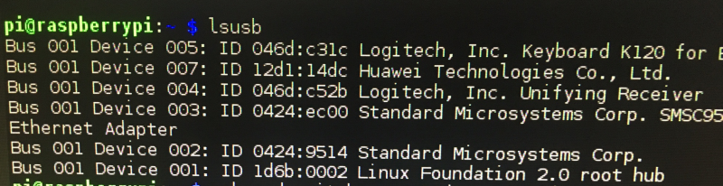
Let's connect the E3531 to the USB port on the pi! Now run the 'lsusb' command to list usb devices attached to pi. Hopefully you'll get the following:
![]()
As you can see we got ID 12d1:14dc so that's great. It's in HiLink-CDC-Ethernet mode! That's supposed to be the default state for the E3531 so you don't need to worry about it being stuck in mass storage mode like the E303.
Now we can use the Huawei HiLink to set everything up to connect to our carrier. Go to the web-browser, and access http://192.168.8.1 . Then you'll get the home html file giving your status:
![]()
Then you can go along to settings and enter your carrier information. So once you get connect, you are all ready to access the internet using PPP via eth1! That was all quite easy!
2.
Next, let's switch it to a serial modem so we can send AT commands to get out SMS messages in lower connectivity scenarios. We'll be wanting to access it as tty/USBx
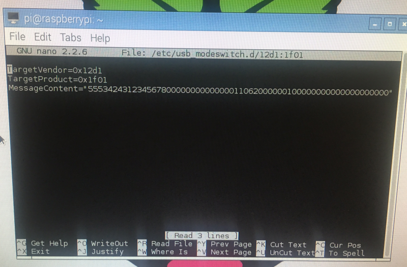
We need to switch our E3531 mode from 12d1:14dc to modem mode i.e. 12d1:1001 with 3x virtual serial ports. Let's get started by downloading and installing usb-modeswitch:
sudo apt-get install usb-modeswitchNo let's make a file containing our switch mode instructions. The instructions are:
TargetVendor=0x12d1
TargetProduct=0x1f01MessageContent="55534243123456780000000000000011062000000100000000000000000000"
The message content depends on the firmware of your E3531, so honesty, the above might not work and you'll have to experiment/research to find a message that does :-(
Right, so let's make the file for usb-modeswitch to use:
sudo nano /etc/usb_modeswitch.d/12d1:1f01![]() and add those instructions to the file! Then save it. Then reboot the pi.
and add those instructions to the file! Then save it. Then reboot the pi.Now after reboot, we can issue the following command: 'lsusb' and we should see the new ID as 12d1:1001 so the E3531 has switched to serial modem mode!
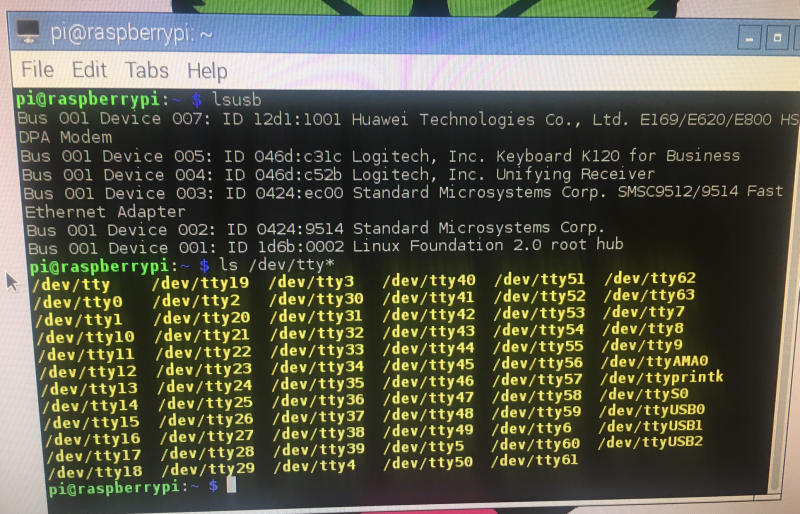
If we issue the command ls /dev/tty* we'll see our virtual serial ports: ttyUSB0, ttyUSB1 and ttyUSB2! Great!
![]()
3.
Now we can go ahead and connect to the virtual serial ports and issue some AT commands! I used cu "call up another system" (https://linux.die.net/man/1/cu) to do this.
sudo apt-get install cuSo after you've installed it, execute it with following arguments to connect to ttyUSB0:
cu -l /dev/ttyUSB0Now I went ahead and sent some AT commands. Sadly they don't echo, so you can't see them!
The first was 'AT' and I got back OK. Then I issued 'AT+CMGF=1' which tells the modem to act in SMS mode, and got back CMS ERROR 302, which is operation not allowed. Then I tried to send an SMS with 'AT+CMGS="+443283870634" <CR>' which returned an error code of CMS ERROR 302 again! These errors are likely due to the SIM card requiring a PIN or PIN2. If the SIM is blocked, the error would be due to SIM required PUK or PUK2 (personal unblocking codes).
![]()
You can send a PIN using AT+CPIN="0000" <CR>. Note that carriers will block the SIM after 3x incorrect PIN attempts, and you will need to use a PUK or PUK2 to unblock it. All the carriers have default PIN codes.
* It turned out that the error was due to me not entering AT+CMGF=1 correctly, not a PIN problem after all!
You can find a full list of error codes here: http://www.smssolutions.net/tutorials/gsm/gsmerrorcodes/
4.
Ok, let's get started with doing this using python instead of cu:
Here's some rough code to send an SMS:
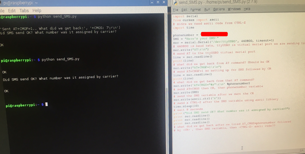
import serial
from curses import ascii
# since we need ascii code from CTRL-Z
import time

phonenumber = #enter phone number to send SMS to
SMS = #enter SMS to send
ser = serial.Serial('/dev/ttyUSB0', 460800, timeout=1)
# 460800 is baud rate, ttyUSB0 is virtual serial port we are sending to
ser.write("AT\r\n")
# send AT to the ttyUSB0 virtual serial port
line = ser.readline()
print(line)
# what did we get back from AT command? Should be OK
ser.write("AT+CMGF=1\r\n")
# send AT+CMGF=1 so setting up for SMS followed by CR
line = ser.readline()
print(line)
# what did we get back from that AT command?
ser.write('AT+CMGS="%s"\r\n' %phonenumber)
# send AT+CMGS then CR, then phonenumber variable
ser.write(SMS)
# send the SMS variable after we sent the CR
ser.write(ascii.ctrl('z'))
# send a CTRL-Z after the SMS variable using ascii library
time.sleep(10)
# wait 10 seconds
print ser.readline()
print ser.readline()
print ser.readline()
print ser.readline()
# what did we get back after we tried AT_CMGS=phonenumber followed
# by <CR> , then SMS variable, then <CTRL-Z> ascii code??
GitHub here: https://github.com/nksheridan/elephantAI/blob/master/test_send_sms.py
So, after running that, we are able to send an SMS! The phone numbers have to be entered in + then country code, then number format e.g +441234123123
![]()
![]()
CONCLUSION
So we are all ready to deploy the E3531 as a mobile connectivity solution to the elephant detection devices, and we've got the code we need to notify local people via SMS of elephants being present!
We'll cover using PPP to alert people via twitter in another log (if there's time, or as a future development). In this PPP scenario, we'd could send tweets (or DMs) which included the images of suspected elephants to the local people (users). We could also send this data to a computer in the village that would plot the location of elephants onto google maps/custom maps. In addition, the computer could output to a big physical map sign containing LEDs corresponding to elephant detection devices (these lighting up!). This computer again could comprise a raspberry pi!
In a more advanced PPP scenario I have envisaged, the input of local people could be leveraged to improve the accuracy of our elephant detector by enabled a supervised training system. Here's what it would look like:
1. Elephant detector tweets/DMs image of suspected elephant
2. Local people tweet back with hashtags #yeselephant #noelephant #type_is_lone #type_is_calf
#type_is_herd #type_is_male #type_is_female according to what they identify in the image
3. Database of images containing elephants confirmed by users is created by elephant detection device
4. Images being stored along with their class labels that were provided via the hashtags (e.g. #type_is_calf , #type_is_herd etc.)
5. On a weekly or monthly basis, the elephant detection devices will upload their databases of images to the cloud (e.g. to an Amazon EC2 virtual machine)
6. Transfer learning will be performed on the virtual machine using our existing dataset with these additional images. Thus improving the accuracy of our elephant detector model!
7. The new model will be sent to the elephant detection device from the cloud-based virtual machine, and be used for future detection.
This process will be repeated on a weekly or monthly basis, thus providing on-going improvements in accuracy of the elephant detector!
* please see the future directions log for this and other improvement ideas!
Elephant AI
a system to prevent human-elephant conflict by detecting elephants using machine vision, and warning humans and/or repelling elephants

 and add those instructions to the file! Then save it. Then reboot the pi.