Neil K. Sheridan
-
#software : switching between raspberry pi depending on day/night
10/09/2017 at 20:11 • 0 commentsWhat's the problem?
We use two raspberry pi computers! One for daytime elephant detection, and one for night-time elephant detection. One having NoIR camera + IR illumination, and one having IR-filtered camera. In addition, only one has mobile connectivity. So they both need to communicate! The daytime detection raspberry pi must tell the night-time detection pi when it is night! And the night-time detection raspberry pi must tell the daytime when it is day - based on what their respective light sensors inform them!
So, we looked at some approaches to do this here: https://hackaday.io/project/20448-elephant-ai/log/67566-switching-between-raspberry-pi-depending-on-lighting-daynight .
The problem is that we can't multiplex raspberry pi IR and NoIR cameras to the CSI port. Well, we can using http://www.ivmech.com/magaza/en/development-modules-c-4/ivport-v2-raspberry-pi-camera-module-v2-multiplexer-p-107 I guess, but it's kinda expensive at $77 + shipping + taxes. And we could perhaps use a Raspberry Pi camera on the CSI + a webcam etc. via USB (e.g.https://www.raspberrypi.org/documentation/usage/webcams/ ) .
You might think we could communicate between the two raspberry pi computers (we'll refer to them as dayPI and nightPI from now one) via serial. But we can't do that, because one of them is using serial to communicate with the cellular network (2G/3G/GPRS) modem!
Anyway, so first here I'll go through software ideas for connecting two raspberry pi's together using Ethernet cable. Then I'll show what I did.
1. Send and receive UDP with DGRAM as proof of concept (code concept)
UDP_IP = "IP_OF_RECEIVER" UDP_PORT = 5005 # we need an unassigned port MESSAGE = "It's night-time!" print "UDP target IP:", UDP_IP print "UDP target port:", UDP_PORT print "message:", MESSAGE sock = socket.socket(socket.AF_INET, # Internet socket.SOCK_DGRAM) # UDP sock.sendto(MESSAGE, (UDP_IP, UDP_PORT))import socket UDP_IP = "IP_OF_RECEIVER" UDP_PORT = 5005 sock = socket.socket(socket.AF_INET, # Internet socket.SOCK_DGRAM) # UDP sock.bind((UDP_IP, UDP_PORT)) while True: data, addr = sock.recvfrom(1024) # buffer size is 1024 bytes #buffer size to prevent overflow print "received message:", dataThis is UDP with socket.SOCK_DGRAM is a datagram socket. Order and reliability for message is not guaranteed for these type of sockets. Alternatively we use socket.SOCK_STREAM for TCP which is sequenced (https://en.wikipedia.org/wiki/Stream_socket)
Here we go with an example code idea for the server with TCP and SOCK_STREAM:
import socket
host = 'host IP'
post = 5580
message = "this is a message"
def setupServer():
    s = socket.socket(socket.AF_INET, socket.SOCK_STREAM)
    print("Socket made")
    try:
        s.bind(host, port)
    except socket.error as msg:
        print(msg)
    print("Binded to socket")
    return s
def setupConnection():
    s.listen(1) # one connection only at a time
    conn, address = s.accept()
    print("connection to: " + address[0] ":" + str(address[1]))
    return conn
def GET():
    reply = storedValue
    return reply
def dataTransfer(conn):
    while True:
    #receive data
        data = conn.recv(1024)
        data = data.decode('utf-8')
        #this is for split with first bit of string having a command word
        dataMessage = data.split(' ', 1)
        command = dataMessage[0]
        if command == 'GET':
            reply = GET()
        elif command == 'REPEAT':
            reply = REPEAT(dataMessage)
        elif command == 'EXIT':
            print("no client")
            break
        elif command == 'KILL':
            print("server shut down now")
            s.close()
            #close socket
            break
        else:
            reply = 'Unknown command given'
        # send reply to client
    conn.sendall(str.encode(reply))
    print("Data sent to client")
    conn.close()
def REPEAT(dataMessage):
    reply = dataMessage[1]
    # so the split from second bit of string.. [0] was the command
    # this is just proof of concept
    return reply
s = setupServer()

while True:
    try:
        conn = setupConnection()
        dataTransfer(conn)
    except:
        break
Here we go for the client:
import socket
host = 'IP address'
port = 'port as same'
s = socket.socket(socket.AF_INET, socket.SOCK_STREAM)
s.connect((host, port))
while True:
    command = input("client enter your command:")
    if command == 'EXIT':
        # send the EXIT command to server
        s.send(str.encode(command))
        break
    elif command == 'KILL':
        # send the KILL command to server
        s.send(str.encode(command))
        break
    s.send(str.encode(command))
    #send other commands to server
    reply = s.recv(1024)
    #buffer size
    print(reply.decode('utf-8'))
s.close()
#close socket
2.
Now, I didn't find much point is using that.. So I just used DGRAM. This is a demo of using DGRAM (datagram) over Ethernet for enabling communication between the dayPi and the nightPi:
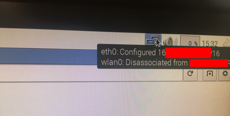
Now before trying this, you need to find the IPs of your dayPi and nightPi! You can do this is the GUI by hovering with the mouse over the icons on top right of screen:
![]()
There is is! Under eth0.
Or you can run:
sudo ifconfigOk, so off we go with the demo code..
So here's the code you need to run on the dayPi:
import socket
import time
UDP_IP = "THIS IS THE IP OF DETECTION DEVICE TO BE SENT THE MESSAGE"
UDP_PORT = 5005
MESSAGE= "NIGHT"
print("Debug: UDP_IP is ", UDP_IP)
print("Debug: UDP_PORT is ", UDP_PORT)
time.sleep(2)
print("Debug: I am the daytime elephant detection device and I am monitoring light levels")
time.sleep(2)
print("Debug: It is night time time now! I will send a message telling the night detection device")
time.sleep(2)
print("Debug: Sending my message")
sock = socket.socket(socket.AF_INET, socket.SOCK_DGRAM)
sock.sendto(MESSAGE, (UDP_IP, UDP_PORT))
print("Debug: Sent messsage. Now I will begin waiting for a message back when it is morning")
time.sleep(2)
sock.close()
print("Debug: I will create a socket and wait listening to it")
print("Debug: I am going to start waiting now")
UDP_IP = "THIS IS THE IP OF THIS DETECTION DEVICE TO LISTEN ON"
# bind our own IP to listen
sock = socket.socket(socket.AF_INET, socket.SOCK_DGRAM)
sock.bind((UDP_IP, UDP_PORT))
while True:
    data = sock.recvfrom(1024)
    print("Debug: I just got a message from night-time detection device: ", data)
    if data[0] == "DAY":
        break
print("Debug: I got a message saying it is DAY. Time to begin my detection again")
sock.close()
GitHub: https://github.com/nksheridan/elephantAI/blob/master/demo_Ethernet_comms_DGRAM_dayPi
-- sending a message to nightPi--
Note that initially the dayPi will send a message to the nightPi when its sensor detects that night time condition has occurred. We don't have all that code in at this point - so we just simulate it with the MESSAGE variable being given "NIGHT". So we bind to the socket on the nightPi with 'sock = socket.socket(socket.AF_INET, socket.SOCK_DGRAM)' and send it MESSAGE with 'sock.sendto(MESSAGE, (UDP_IP, UDP_PORT)).
Here UDP_IP is the IP of the nightPi and UDP_PORT is anything that isn't allocated (e.g. 5005)
-- receiving a message back from nightPi --
Now the dayPi will bind to its own socket (same port 5005) so here the UDP_IP is the IP of the dayPi, and wait for a message back from nightPi. We have a while loop that we break out of when the message is equal to "DAY". The dayPi will perform its detection duty at this point, and be prepared to do the whole process again when night time condition occurs again!
And here's the code you need to run on the nightPi:
import socket
import time
UDP_IP = "THIS IS OUR OWN IP TO LISTEN ON"
UDP_PORT = 5005
sock = socket.socket(socket.AF_INET, socket.SOCK_DGRAM)
sock.bind((UDP_IP, UDP_PORT))
print("Debug: I am the night-time elephant detection pi")
time.sleep(2)
print("Debug: I am waiting for my message from the daytime elephant detection pi")
time.sleep(2)
print("Debug: I will stop listening when I receive a data message that contains NIGHT")
time.sleep(2)
print("Debug: I am waiting now!")
while True:
    data = sock.recvfrom(1024)
    print("Debug: got the following message from dayPi: ", data[0])
    if data[0] == "NIGHT":
        break
print("Debug: I got the NIGHT message so I quite waiting for a message!")
time.sleep(2)
print("Debug: Now I will perform elephant detection and monitor light condition")
time.sleep(2)
print("Debug: I will prepare to send a message to the dayPi when morning occurs!")
time.sleep(2)
#variable for light condition. Updated by light sensor
light = 0
#light is 0 for dark, and 1 for light
print("Debug: Currently light is ", light)
time.sleep(2)
light = 1
#simulate light being 1
print("Debug: Currently light is ", light)
time.sleep(2)
print("Debug: Now it is time to message the dayPi since light is 1")
UDP_IP = "IP OF THE dayPi"
# IP of the dayPi
MESSAGE = "DAY"
sock = socket.socket(socket.AF_INET, socket.SOCK_DGRAM)
sock.sendto(MESSAGE, (UDP_IP, UDP_PORT))
print("Debug: I sent a message to the dayPi: ", MESSAGE)
time.sleep(2)
print("Debug: Now I wait for a message back when it is night again!")
sock.close()
It's the same method for sending messages back and forth, as we explained for the dayPi above, but with alterations for UDP_IP and the messages sent!
GitHub: https://github.com/nksheridan/elephantAI/blob/master/demo_Ethernet_comms_DGRAM_nightPi
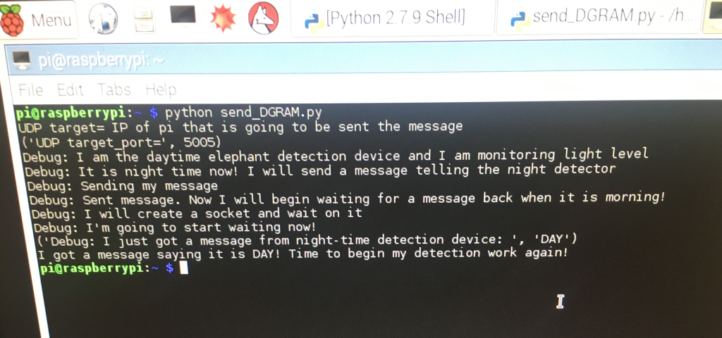
Here's what we get back when we run those two bits of code (if you didn't watch the video!). First off, this is what the dayPi gets:
![]()
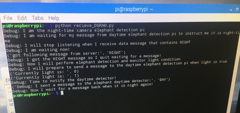
And, here's what the nightPi gets:
![]()
3.
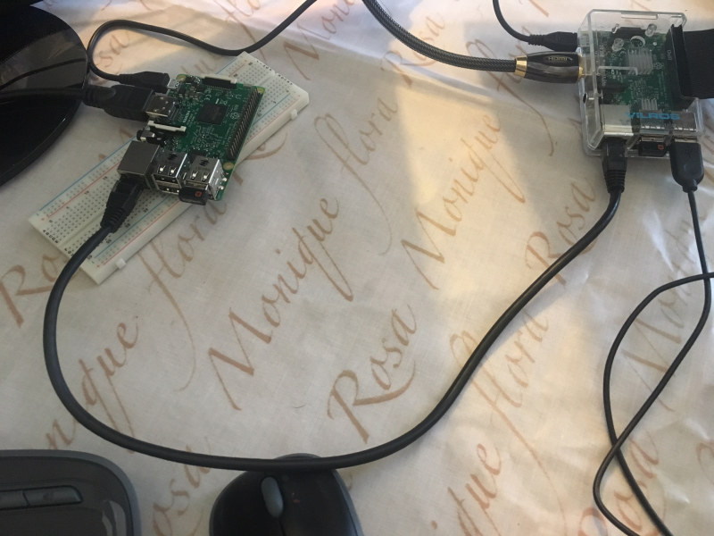
How do we connect the dayPi and nightPi? We just connect them with an Ethernet cable from their Ethernet ports!
![]()
4.
So that was fairly simple! And we just used DGRAM.
CONCLUSION
Another issue we can solve with this comms method is the fact that only one of the detection devices will have mobile connectivity! So if the other detection device, that doesn't have mobile connectivity (via either HAT or USB dongle) , detects an elephant, what can it do? Well it can send a message to the detection device that does have mobile connectivity using this method! Then that device can send the message out!
Another approach would be to multiplex the inputs to the mobile connectivity device so both detection devices can output to it. This should be ok for the HATs, but rather difficult involving cable splitting for the dongles
*there's a worry about impact of RF comms
-
#software elephant detector: transfer learning off-shelf model with TensorFlow
10/08/2017 at 18:52 • 0 commentsThis is probably the easiest way to perform transfer learning on an off-shelf model (InceptionV3 here) in order to add our additional elephant classes, and thus build elephant detector software. We're using scripts from the TensorFlow github repository https://github.com/tensorflow/tensorflow . These are all licensed under Apache License, Version 2.0 (the "License") unless otherwise stated.
GETTING STARTED
We are using a machine with a GPU. In this case a NVIDIA Tesla® K80 GPU. So TensorFlow is installed alongside with CUDA® Toolkit 8.0, cuDNN v6, and NVIDIA CUDA Profile Tools Interface, giving GPU-support. So it's really fast at doing this work! This is an Amazon EC2 virtual machine. We went over how to get started with these in this log https://hackaday.io/project/20448-elephant-ai/log/56127-instructions-for-using-ec2-instance-to-train-object-detector-in-progress . It just covers things like setting the correct permissions for your keypair (which people have trouble with), using SSH, and SCP. I'll try and add a full guide to using Amazon EC2.
PREPARING IMAGES
For this example, we are using two additional classes of elephants: herd_elephants, and lone_elephants. So we set up a directory structure as follows:
+ elephant_images
+ herd_elephants
+ lone_elephants
Go ahead and place the corresponding elephant images into the sub-directories. It doesn't matter what the image file names are. The labels for the new classes are taken from the directory names. Don't worry about the image sizes. Those used in this example are around 2048*1536 in size.
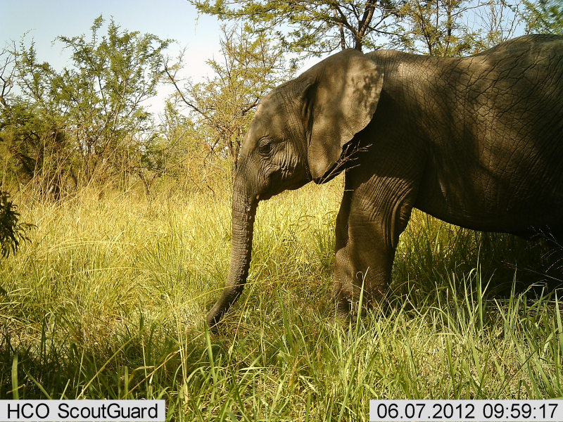
Here's an example of a herd elephant image (for the herd_elephant class):
![]()
Here's an example of a lone elephant image (for the lone_elephant class):
![]()
* this image and the other training images are used for training with permission from the Snapshot Serengeti Project. The images are acquired from automated camera traps.
I used GIMP to crop the images. I removed the camera trap data from the bottom.
Ok, so once you've sorted all your elephant images, you can upload the directory containing them to your virtual machine using scp. Or not if you are doing it locally. We went over the use of keypairs in the earlier guide [https://hackaday.io/project/20448-elephant-ai/log/56127-instructions-for-using-ec2-instance-to-train-object-detector-in-progress]. Just remember to set the correct permissions on these! In this example the keypair.pem is in current directory.
scp -i myAmazonKey.pem -r elephant_images ec2-user@mec2-50-15-16-67.compute-1.amazonaws.com:~/.RETRAINING THE OFF-SHELF MODEL
We are going to use retrain.py from the TensorFlow github repository and its dependencies to perform transfer learning on Inception V3 to add our new elephant classes. So go to your virtual machine now.
1. First you can clone the TensorFlow github repository to get the code. It gets quite a bit we don't need but at least you won't get mixed up! You can just get the code you need instead if you want!
git clone https://github.com/tensorflow/tensorflow.git2. Now let's look at the retrain.py code! You can find it in ' tensorflow/tensorflow/examples/image_retraining/' Here is is -> https://github.com/tensorflow/tensorflow/blob/master/tensorflow/examples/image_retraining/retrain.py
Here are the libraries it uses, in case you don't want to bother cloning the entire github:
from __future__ import absolute_import
from __future__ import division
from __future__ import print_function
import argparse
from datetime import datetime
import hashlib
import os.path
import random
import re
import sys
import tarfile
import numpy as np
from six.moves import urllib
import tensorflow as tf
from tensorflow.python.framework import graph_util
from tensorflow.python.framework import tensor_shape
from tensorflow.python.platform import gfile
from tensorflow.python.util import compat
3. Anyway, let's go ahead and use it! What shall we pass to it? Here are some of the important arguments it can be passed. Yes, there are quite a few! And even more if you take a look at the code!
 '--image_dir',
      type=str,
      default='',
      help='Path to folders of labeled images.'

      '--output_graph',
      type=str,
      default='/tmp/output_graph.pb',
      help='Where to save the trained graph.'
'--output_labels',
      type=str,
      default='/tmp/output_labels.txt',
      help='Where to save the trained graph\'s labels.'
  )
      '--summaries_dir',
      type=str,
      default='/tmp/retrain_logs',
      help='Where to save summary logs for TensorBoard.'
  )

      '--how_many_training_steps',
      type=int,
      default=4000,
      help='How many training steps to run before ending.'
  )

      '--learning_rate',
      type=float,
      default=0.01,
      help='How large a learning rate to use when training.'
  )

      '--testing_percentage',
      type=int,
      default=10,
      help='What percentage of images to use as a test set.'
  )
      '--validation_percentage',
      type=int,
      default=10,
      help='What percentage of images to use as a validation set.'
  )
      '--eval_step_interval',
      type=int,
      default=10,
      help='How often to evaluate the training results.'
  )
      '--train_batch_size',
      type=int,
      default=100,
      help='How many images to train on at a time.'
  )

      '--test_batch_size',
      type=int,
      default=-1,
      help="""\
      How many images to test on. This test set is only used once, to evaluate
      the final accuracy of the model after training completes.
      A value of -1 causes the entire test set to be used, which leads to more
      stable results across runs.\
      """
  )

      '--validation_batch_size',
      type=int,
      default=100,
      help="""\
      How many images to use in an evaluation batch. This validation set is
      used much more often than the test set, and is an early indicator of how
      accurate the model is during training.
      A value of -1 causes the entire validation set to be used, which leads to
      more stable results across training iterations, but may be slower on large
      training sets.\
      """
 '--architecture',
      type=str,
      default='inception_v3',
      help="""\
      Which model architecture to use. 'inception_v3' is the most accurate, but
      also the slowest. For faster or smaller models, chose a MobileNet with the
      form 'mobilenet__[_quantized]'. For example,
      'mobilenet_1.0_224' will pick a model that is 17 MB in size and takes 224
      pixel input images, while 'mobilenet_0.25_128_quantized' will choose a much
      less accurate, but smaller and faster network that's 920 KB on disk and
      takes 128x128 images. See https://research.googleblog.com/2017/06/mobilenets-open-source-models-for.html
      for more information on Mobilenet.\
4. Let's get started! We'll stick with the defaults mostly. For instance we are using InceptionV3 as the architecture. But let's alter '--output_graph' (help='Where to save the trained graph), '--output_labels',(help='Where to save the trained graph's labels.'), and we certainly need to set '--image_dir'.
Here we go! We scp'ed the elephant_images to root, so we'll set that as image_dir. And we'll dump the output graph and output labels to root too! We're ready to go now! Make sure you are in the directory containing retrain.py and issue the command:
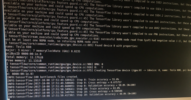
python retrain.py --image_dir ~/elephant_images --output_graph ~/output_graph.pb --output_labels ~/labels.txtNow we should be on our way to retraining InceptionV3 with our new elephant classes!
![]()
5. Once we've finished we should find output_graph.pb and labels.txt in root! Don't forget to check out labels.txt , and see if it contains the labels/classes of herd_elephant and lone_elephant!
RUNNING IMAGE CLASSIFICATION WITH THE RETRAINED MODEL
6. Great! Now we can see what happens when we try image classification with the model we made using our new elephant classes!
We are going to use label_image.py to do this https://github.com/tensorflow/tensorflow/blob/master/tensorflow/examples/image_retraining/label_image.py -- go ahead and have a look at it. It's in the image_retraining directory if you cloned the repository.
Here are the libraries it uses (nothing exciting or to mix us up!):
from __future__ import absolute_import
from __future__ import division
from __future__ import print_function
import argparse
import sys
import tensorflow as tf
So, it has argparse! What arguments are we going to pass to it?
We'll just pass these:
  '--image', required=True, type=str, help='Absolute path to image file.'
    '--num_top_predictions',
    type=int,
    default=5,
    help='Display this many predictions.'
    '--graph',
    required=True,
    type=str,
    help='Absolute path to graph file (.pb)')
    '--labels',
    required=True,
    type=str,
    help='Absolute path to labels file (.txt)')
So, --image is going to be the image we want to classify! --num-top_predictions is how many predictions we want as to what that image might be classed as. Whilst --graph is path to graph file output_graph.pb, and --labels is going to be path to labels.txt
You can scp an elephant image from your local machine, or wget one from something you found via google images search etc to use as the testing image for classification. Try an image of a herd of elephants and see if that gives a prediction of herd_elephants! I
7.
Ok, so let's run the code passing the arguments! The output_graph.pb and the labels.txt and the image to classify are in the local directory.
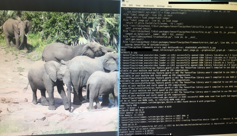
python label_image.py --graph=output_graph.pb
  --labels=labels.txt
  --image=elephant_photo_you_found.jpg
8.
Here's what I got for a random herd of elephants photo I downloaded! "elephant_herd" score was 0.98737.
![]()
Right! So hopefully that worked! Now it is just a case of choosing appropriate images for your new classes, increasing the number of images, and adjusting the hyperparameters that are passed to retrain.py!
For instance, you could adjust the '--learning_rate' hyperparameter/argument. This controls magnitude of the updates to the final layer of the CN during retraining. The default was 0.01. Using a smaller value might increase precision, but take longer for the retraining. I'll cover hyperparameters in another log.
You might want to use TensorBoard too in order to visualize what's going on/debug/see how the hyperparameter optimisation is going: https://www.tensorflow.org/get_started/summaries_and_tensorboard
HOW MANY IMAGES PER CLASS
We certainly want the same number of images per class - else the model is going to be skewed to the certain class that has more images! I'm using 1000+ per class.
WORKING WITH THE OUTPUT FROM LABEL_IMAGE.PY
So this is important for our final code! We want to tell the rest of the program if we got an elephant! So we need to extract the score and make sure this is above 0.90. And we also want to keep track of the elephant types, so we can send these to the system users in SMS or other message!
# Sort to show labels in order of confidence
    top_k = predictions.argsort()[-num_top_predictions:][::-1]
    for node_id in top_k:
      human_string = labels[node_id]
      score = predictions[node_id]
      print('%s (score = %.5f)' % (human_string, score))
So that's our relevant bit of code from label_image.py :
For node_id in top_k i.e. the prediction number (node_id) in the top 5 predictions (top_k) it will write the label (i.e. the elephant class) to human_string and the prediction (e.g. 0.98732) to score. And then it prints them.
So the easiest thing for us to do is alter that slightly by sending these to some new variables:
first_prediction_class = labels[1]
first_prediction_score - predictions[1]
second_prediction_class = labels[2]
second_prediction_score = predictions[2]
Now we could make those all global variables, so we can access them outside the function, or we can get the function to return them in a list. For this we shall set up a list to put them in with:
detected_animals_list = [ ]
Then we populate the list with these variables:
detected_animals_list[1] = first_prediction_class
detected_animals_list[2] = first_prediction_score
detected_animals_list[3] = second_prediction_class
detected_animals_list[4]= second_prediction_score
Then we get the function to return the list i.e. return detected_animals_list
So this is the rough initial concept I came up with for taking required code from label_image.py, adding additional required code, and making it into a function to incorporate in the final detection device code:
def load_graph(filename): #this is the graph file that we get after retraining the off-shelf model with our #new elephant classes """Unpersists graph from file as default graph.""" with tf.gfile.FastGFile(filename, 'rb') as f: graph_def = tf.GraphDef() graph_def.ParseFromString(f.read()) tf.import_graph_def(graph_def, name='') def run_graph(image_data, labels, input_layer_name, output_layer_name, num_top_predictions): with tf.Session() as sess: # Feed the image_data as input to the graph. # predictions will contain a two-dimensional array, where one # dimension represents the input image count, and the other has # predictions per class softmax_tensor = sess.graph.get_tensor_by_name(output_layer_name) predictions, = sess.run(softmax_tensor, {input_layer_name: image_data}) # Sort to show labels in order of confidence top_k = predictions.argsort()[-num_top_predictions:][::-1] first_prediction_class = labels[1] first_prediction_score - predictions[1] second_prediction_class = labels[2] second_prediction_score = predictions[2] #for node_id in top_k: # human_string = labels[node_id] # score = predictions[node_id] # print('%s (score = %.5f)' % (human_string, score)) detected_animals_list = [ ] detected_animals_list[1] = first_prediction_class detected_animals_list[2] = first_prediction_score detected_animals_list[3] = second_prediction_class detected_animals_list[4]= second_prediction_score return detected_animals_list # load image image_data = load_image(filename_for_image) # load labels labels = load_labels(filename_here) # load graph, which is stored in the default session load_graph(filename) run_graph(image_data, labels, FLAGS.input_layer, FLAGS.output_layer, FLAGS.num_top_predictions) #return the detected animals list return detected_animals_list -
#software installing on Rasp Pi, and detection w TensorFlow & Keras (off-shelf)
10/07/2017 at 19:16 • 0 commentsHere we use Tensorflow and Keras for elephant detection by importing an off-shelf model for image classification. We can import one of the following models with keras.applications:
Xception
VGG16
VGG19
ResNet50
InceptionV3
InceptionResNetV2
Keras documentation for keras.applications: https://keras.io/applications/
1.
First let's get this working without using a Raspberry Pi. In this case we are using a machine running ubuntu with a NVIDIA Tesla® K80 GPU. So TensorFlow is installed alongside with CUDA® Toolkit 8.0, cuDNN v6, and NVIDIA CUDA Profile Tools Interface, giving GPU-support.
Anyway, so go ahead and install TensorFlow and Keras with or without GPU-support, depending which machine you are using.
You can install TensorFlow using instructions here: https://www.tensorflow.org/install/install_linux
You can install Keras using instructions here: https://keras.io/#installation
* I won't go through installation, since it depends which machine you are using
2.
Right, so everything should be ready now! You can test TensorFlow with the hello world code in python! That doesn't mean everything will work fine tho! I've messed up several installations in some way!
import tensorflow as tf
hello = tf.constant('Hello, TensorFlow!')
sess = tf.Session()
print(sess.run(hello))
3.
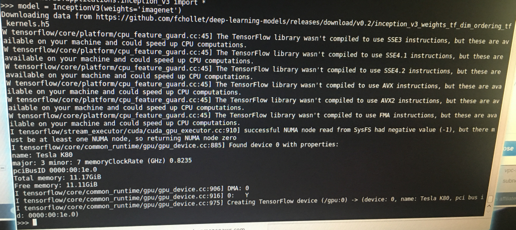
Now, let's run python. In this case Python 2.7. And we'll enter the code required to classify and image using an off-shelf model. In this case it was Inception V3.
![]()
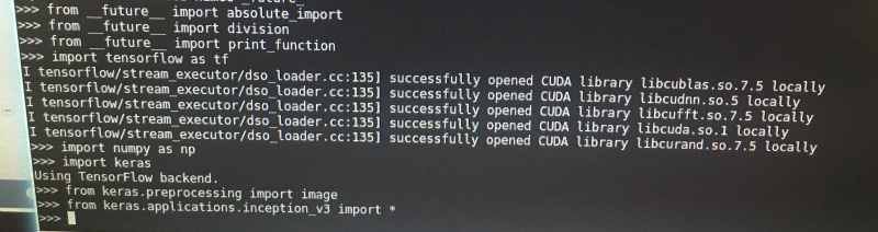
First we imported our libraries:
from __future__ import absolute_import from __future__ import division from __future__ import print_function import numpy as np import keras import tensorflow as tf from keras.preprocessing import image from keras.applications.inception_v3 import *![]()
4.
Next we set model to InceptionV3 with the imagenet weights:
model = InceptionV3(weights='imagenet')Now you can see in the above image what happens when we do that! It downloads the weights h5 file " WEIGHTS_PATH = 'https://github.com/fchollet/deep-learning-models/releases/download/v0.5/inception_v3_weights_tf_dim_ordering_tf_kernels.h5'", and then it throws up some information that we don't have various CPU instruction sets installed. Then it reports our GPU "Found device 0 with properties name: Tesla K80" Then it reports memory available, and sets the Tesla K80 as our TensorFlow device.
5.
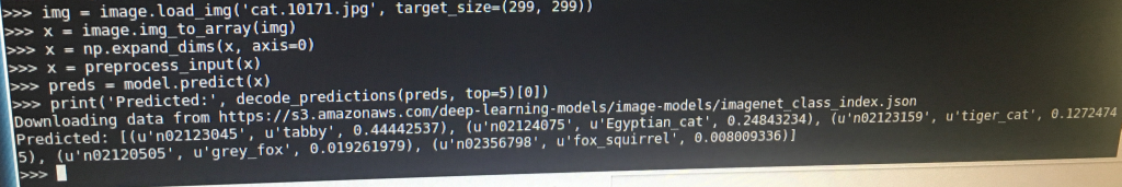
Now we go ahead and work on the image we want to classify with InceptionV3:
img = image.load_img('cat.10171.jpg', target_size=(299, 299))
x = image.img_to_array(img)
x = np.expand_dims(x, axis=0)
x = preprocess_input(x)
So in the first line we load the image using 'image.load_img'. That's from the image part of the keras.preprocessing library we imported earlier.
It's important to note the target_size! Different off-shelf models require images to be of certain fixed sizes. So we resized to 299x299. ResNet50 would require 224x224.
In the second line we change img to an array with 'image.img_to_array' from the keras.preprocessing library.
In the third line we use numpy to expand the shape of the array e.g.
>>> y = np.expand_dims(x, axis=0)
>>> y
array([[1, 2]])
>>> y.shape
(1, 2)
In the fourth line we use 'preprocess_input' from the keras.preprocessing library. This will return a preprocessed tensor. You can see the code in
https://github.com/fchollet/keras/blob/master/keras/applications/imagenet_utils.py
6.Ok, so next we want to get the predictions for that image from the InceptionV3 model! What is the image? So we enter:
preds = model.predict(x)model.predict is from keras.models. It is passed the following arguments: predict(self, x, batch_size=None, verbose=0, steps=None). x being the input data, as a numpy array which we made. See documentation: https://keras.io/models/model/ . We just gave it x.
model.predict will return a list of tuples: class, description, probability -> to preds in this case.
So we've got the preds being a numpy tensor right now. We go ahead and decode it with 'decode_predictions' from the https://github.com/fchollet/keras/blob/master/keras/applications/imagenet_utils.py . We passed it preds, and we passed it top. Top is integer as to how many guesses we want back. In this case top=5.
![]()
Then print it with print from: __future__ import printfunction:
print('Predicted:', decode_predictions(preds, top=5))So we got back:
class_name = n02123045
class_description = tabby
probability = 0.44442537
Quite exciting! You could plot the predictions using matplotlib.pyplot too. And use
argparse if you don't want to hard-code the image name.
7.
Install TensorFlow and Keras on Raspberry Pi
-- Use pip same as for ubuntu machine
8.
[under construction]
-
Elephant Detector Approaches using CNs
10/06/2017 at 20:12 • 0 commentsHere are the different approaches:
1. Tensorflow and Keras off-shelf: using keras.applications to import off-shelf model for image classification, with the weights trained on ImageNet. Available models being:
Xception
VGG16
VGG19
ResNet50
InceptionV3
InceptionResNetV2Go ahead and run model prediction for the images acquired from our camera e.g. classify.py which will return predicted labels and 'probabilities'. No new labels/classes added to the model.
Keras documentation: https://keras.io/applications/
We cover how to do this, and how to install TensorFlow and Keras on Raspberry Pi, in this build guide: https://hackaday.io/project/20448-elephant-ai/log/68401-software-installing-on-rasp-pi-and-detection-w-tensorflow-keras-off-shelf
2. Tensorflow and Keras fine-tuning or transfer learning: keras.applications to import off-shelf model (e.g. InceptionV3) then fine-tune or transfer learning with our new labelled images (new classes)
We cover how to do this [here]
3. Tensorflow and TFSlim fine-tuning: so using the TFSlim API, import off-shelf model (e.g. InceptionV3 or VGG19), then fine-tune with our new labelled images (new classes)
TFSlim documentation: https://github.com/tensorflow/models/tree/master/research/slim
We cover how to do this [here]
4. Tensforflow and Bazel transfer learning: transfer learning for e.g. InceptionV3, using common approach detailed in Tensforflow tutorial, with our new labelled images (new classes)
** we won't cover how to do this.
5. Tensorflow transfer learning without bazel: transfer learning for e.g. InceptionV3 using common approach detailed in Tensorflow tutorial (https://codelabs.developers.google.com/codelabs/tensorflow-for-poets/#0) and the retrain code here https://github.com/tensorflow/tensorflow/blob/master/tensorflow/examples/image_retraining/retrain.py
We cover how to do this, in this build guide: https://hackaday.io/project/20448-elephant-ai/log/68436-software-elephant-detector-transfer-learning-off-shelf-model-with-tensorflow
* in the above fine-tune and transfer learn approaches, the labels/classes correspond to directory structure for the training images e.g. /images/lone_elephants would be class "lone_elephants"
6. SSD. See SSD: Single Shot MultiBox Detector (Liu et al) https://www.cs.unc.edu/~wliu/papers/ssd.pdf which is commonly used for video. The following is code from lead author: https://github.com/weiliu89/caffe/tree/ssd . This approach is not likely to be used.
** we won't cover how to do this
-
#software mobile connectivity: Huawei E303
10/04/2017 at 19:18 • 0 comments[under construction - e.g. some details have been omitted at this point]
SETTING UP THE HUAWEI E303 3G DONGLE FOR MOBILE CONNECTIVITY
So advantages here include this 3G dongle being quite ubiquitous - so you won't have problems getting it. The FONA modules can be often out of stock, and some of the other modules are quite hard to source, expensive, and only available from one country.
1. There's an issue powering this from the Raspberry Pi USB port. So you need to use a powered USB hub, i.e. externally powered. That's fine, because we can get power from our battery to it at 5V.
[I have not had this issue]
2. Connect the E303 to the USB port
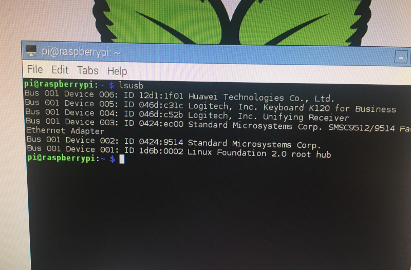
3. Get a list of USB devices from the raspberry pi with
lsusb
Ok, so the second problem may occur at this stage. If we get something similar to Bus 001 Device 010: ID 12d1:----[?] Huawei Technologies Co., Ltd. E303 LTE/UMTS/GSM Modem/Networkcard is the list we are fine.
But if we don't get modem, them we've a problem. For example we got 12d1:1f01 here. The problem is that Raspberry Pi is detecting the E303 as a storage device. This is due to the E303 having a partition on it containing software for windows. Now this can occur intermittently which is real problem! Sometimes listed as a modem, sometimes as a storage device!
Here we go: it was detected as storage device :-(
![]()
You can go ahead and fix this with usb-modeswitch. This will designate a mode to the E303 and store this mode. We need to designate the mode using the hexadecimal value corresponding to modem mode.
The 12d1 is for Huawei, and the 1506 is the device id for a modem. We might have to look these up if we keep getting a storage device detected!
4.
So, let's install usb-modeswitch
sudo apt-get install usb-modeswitchNow we need to edit the config file for usb-modeswitch and insert the correct vendor and device id that corresponds to a modem! The config file is at /etc/usb_modeswitch.conf
Go ahead and edit the file with the following command (or whichever editor you prefer):
sudo nano /etc/usb_modeswitch.confThe mode switch forum can be helpful to get the correct details!
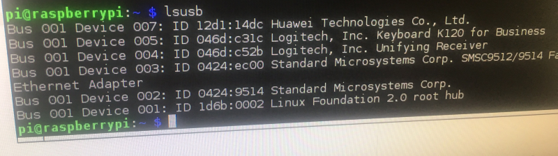
So here's what I found first when I searched for what to add to usb_modeswitch.conf:
DefaultVendor= 0x12d1
DefaultProduct= 0x1f01
TargetVendor= 0x12d1
TargetProduct= 0x14dc
MessageEndPoint = "0x01"
MessageContent="55534243123456780000000000000a11062000000000000100000000000000"
NoDriverLoading=1
So I added this, and yes it the E303 switched from being a storage device (i.e.12d1:1f01) to being a modem (12d1:14dc). So when I ran lsusb again I got:
![]()
So I was thinking I'm all ready to search how to install pppd etc. But when I tried to search from my web browser, I saw this message!!
![]()
Wow! What is going on! wlan, which I was using to connect to internet had been disabled! And eth1 was now associated with the E303! Note, the SIM error is fine, because I didn't have a SIM in the E303 at this point. So the E303 is not acting as a serial modem, it is on Ethernet! With 192.168.1.1 being the gateway and dhcp server. So I found out this is the HighLink mode (see here: https://projects.hologram.io/hologram/working-with-hilink-mode-on-the-huawei-e303-353-58ab21)
So, that's quite good in a way.. If we wanted to use the E303 to have 3G connection to internet using PPP. It's all very easy!
However, we want the E303 to act as a serial modem so we can send AT commands, and get SMS sent out from it! So it the above mode, we can't use screen or cu to start a session with it and try this. E.g. with 'screen /dev/ttyUSB0'
Now we need to make the E303 act as a serial modem!
FORCING THE E303 TO ACT AS A SERIAL MODEM
After some research, I found this could be as simple as passing usb_modeswitch the following:
usb_modeswitch -v 0x12d1 -p 0x1f01 -V 0x12d1 -P 0x1001 -M "55534243000000000000000000000611060000000000000000000000000000"However! A lot of the research I did turned up things people had done in 2013-2015. Has the firmware changed since then? According to this post, from 2016 - which applies to the E3272 rather than E303 - yes! We would need to go back to older firmware in order to force the E3272 to act as serial http://blog.le-vert.net/?p=196 !
we had too:
# Huawei E3531s-2 - switch to modem mode instead of HiLink CDC-Ether mode
TargetVendor=0x12d1
TargetProduct=0x1f01
# switch to 12d1:1001 (modem mode, 3 virtual serial ports)
MessageContent="55534243123456780000000000000011062000000100000000000000000000"
==== these may not be required
5. USING PPPd and others to get PPP over 3G
Ok, now we need to install the Point-to-Point Protocol daemon (pppd) to manage the connection between the pi/E303 and the service provider.
[update background on this daemon]
You can install it with the following command:
sudo apt-get install ppp6.
Well there are several approaches now:
There's the https://github.com/Trixarian/sakis3g-source sakis3g script which we can use [license unknown] to connect to 3G provider. You'll need to pass your APN, SIM PIN (if applicable) and username/password (if applicable).
There's the UMTSkeeper http://mintakaconciencia.net/squares/umtskeeper/index.html- which is to reconnect if the mobile connection is lost.
This is licensed under Hacktivismo Enhanced-Source Software License Agreement (HESSLA) and GNU General Public License (GPL)
=====
JUST USING THE E303 FOR SMS
So here we just send AT commands to the E303. We can do this in python using serial library e.g PysSerial (https://pythonhosted.org/pyserial) , or there are several other methods too.
First we need to instruct the E303 to act in SMS mode with the following AT command:
AT+CMGF=1
We should get back OK. If we don't, we have an error.
Next we send the following command, which includes to phone number to send SMS to:
AT+CMGS="+443283870634" <CR>
It requires a carriage return afterwards, so ASCII code=13 would need to be passed. Next we can send the message, followed by Ctrl-Z, so ASCII code=26:
this is the text message string <CTRL-Z>
At this point we should get back: "+CMGS: x" with x corresponding to the number allocated as an SMS reference number. After that we would get "OK" for the SMS being sent successfully, or we get either "ERROR" or "+CMS ERROR" if the SMS failed to send.
-
Workflow for retraining COCO dataset
10/01/2017 at 19:30 • 0 comments[under construction]
Note this is for a SSD: Single Shot MultiBox Detector
This is for using the COCO dataset (http://cocodataset.org/#home) this is licensed under https://creativecommons.org/licenses/by/4.0/legalcode
First let's set up our directory structure for the entire pipeline:
+ ele_detect
+ data
+ images
- images
- XML files
- CSV file
- Training TFRecord file
- Evaluation TFRecord file
+ models
- [Note to self: please complete this structure using a diagram!!]
-- ANNOTATE IMAGES AND CONVERT TO TFRECORD --
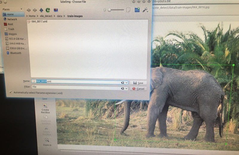
1. Annotate our training images using: https://github.com/tzutalin/labelImg . This will save images in PASCAL VOC format (http://host.robots.ox.ac.uk/pascal/VOC/) using XML.
You can obtain this from PyPi , and run it with:
sudo pip install labelImg
labelImg
You can build it yourself too. Full instructions are on the GitHub link above.
Here it is in action:
![]()
So it's really easy to but bounding boxes around the elephants! And then to give the bounding box a class corresponding to the elephant type e.g. elephant/babyelephant/male.
Then you can go ahead and save the XML file containing the bounding box coordinates, and class, for each image. Shown below:
![]()
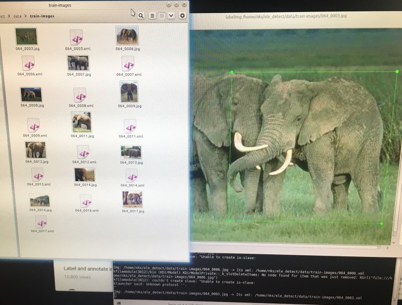
Here are the XML files and their associated images all the the images directory:
![]()
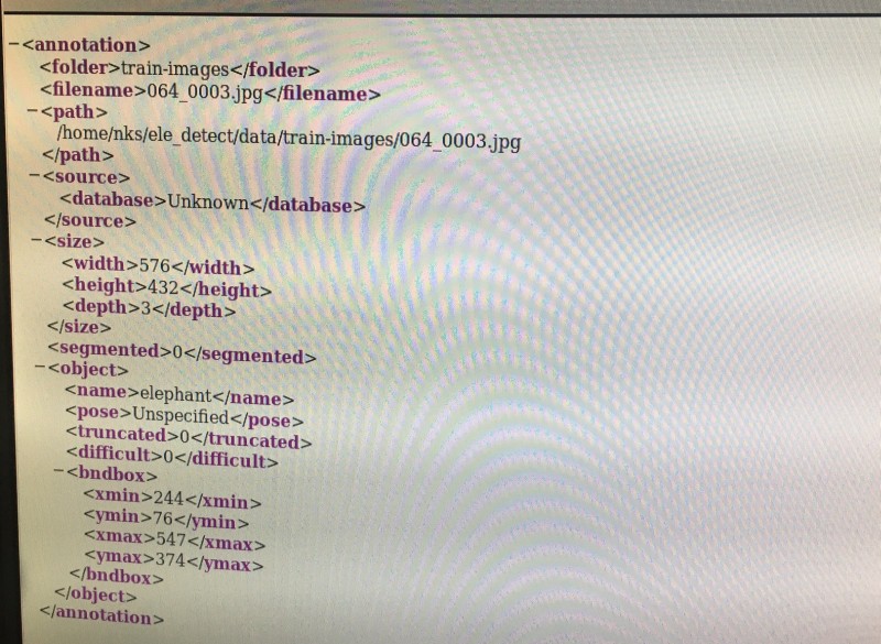
Now, let's see what's in the XML file:
![]()
2. Now we can go ahead and parse + convert these XML files to one CSV file using code written in python.
[code here]
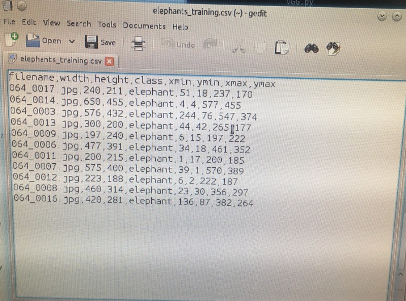
Now, let's see what's in that CSV file. It's everything from the XML files!
![]()
3. Now we are ready to convert the CSV file to TFRecord format for training!
4. Convert CSV to TFRecord for TensorFlow
-- TRAINING MODEL --
5. Download a checkpoint file (model.ckpt-#####) pre-training on COCO dataset via https://github.com/tensorflow/models/blob/master/research/object_detection/g3doc/detection_model_zoo.md There's no need for a fast one. So http://download.tensorflow.org/models/object_detection/faster_rcnn_inception_resnet_v2_atrous_coco_11_06_2017.tar.gz (DL link) is good.
6. Setup your config file (.config)
7. Go ahead with training using https://github.com/tensorflow/models/blob/master/research/object_detection/train.py
** Note that tensorflow code from github.com/tensorflow is licensed under http://www.apache.org/licenses/LICENSE-2.0
8. Export inference graph (.pb) per https://github.com/tensorflow/models/blob/master/research/object_detection/export_inference_graph.py
9. Go ahead with testing
-- USEFUL LINKS --
This is the create_pascal_tf_record.py code from the tensorflow repository to convert raw PASCAL dataset to TFRecord format: https://github.com/tensorflow/models/blob/master/research/object_detection/create_pascal_tf_record.py and this is preprocessor_builder.py: https://github.com/tensorflow/models/blob/a4944a57ad2811e1f6a7a87589a9fc8a776e8d3c/object_detection/builders/preprocessor_builder.py This code is licensed under http://www.apache.org/licenses/LICENSE-2.0
-
#buildinstructions for hardware: safe shutdown switch
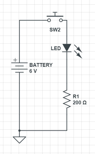
09/29/2017 at 19:03 • 0 commentsThis is the safe shutdown switch circuit, and code, for the detection and deter devices. This is so they can be turned off without risking corruption to their SD cards. This is accomplished by the switches giving a HIGH input to a GPIO pin on the Raspberry Pi when they are pressed. We take power from the VCC 3.3V pin and use the ground pin.
1.
First off to build a test switch circuit on a breadboard, and power it from 6v battery pack. You'll need jump wires with male to male connectors (or just plain wires), a 200 Ohm resistor, an LED, a breadboard, a battery pack, and a momentary push button switch (normally open).
Here's the circuit:
![]()
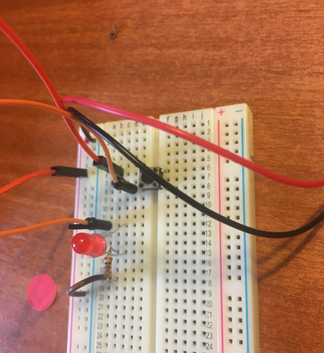
And here's a photo of it on the breadboard:
![]()
Here's a video of the circuit in action!
2.
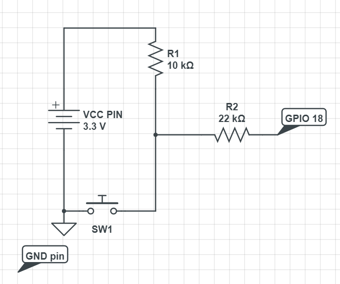
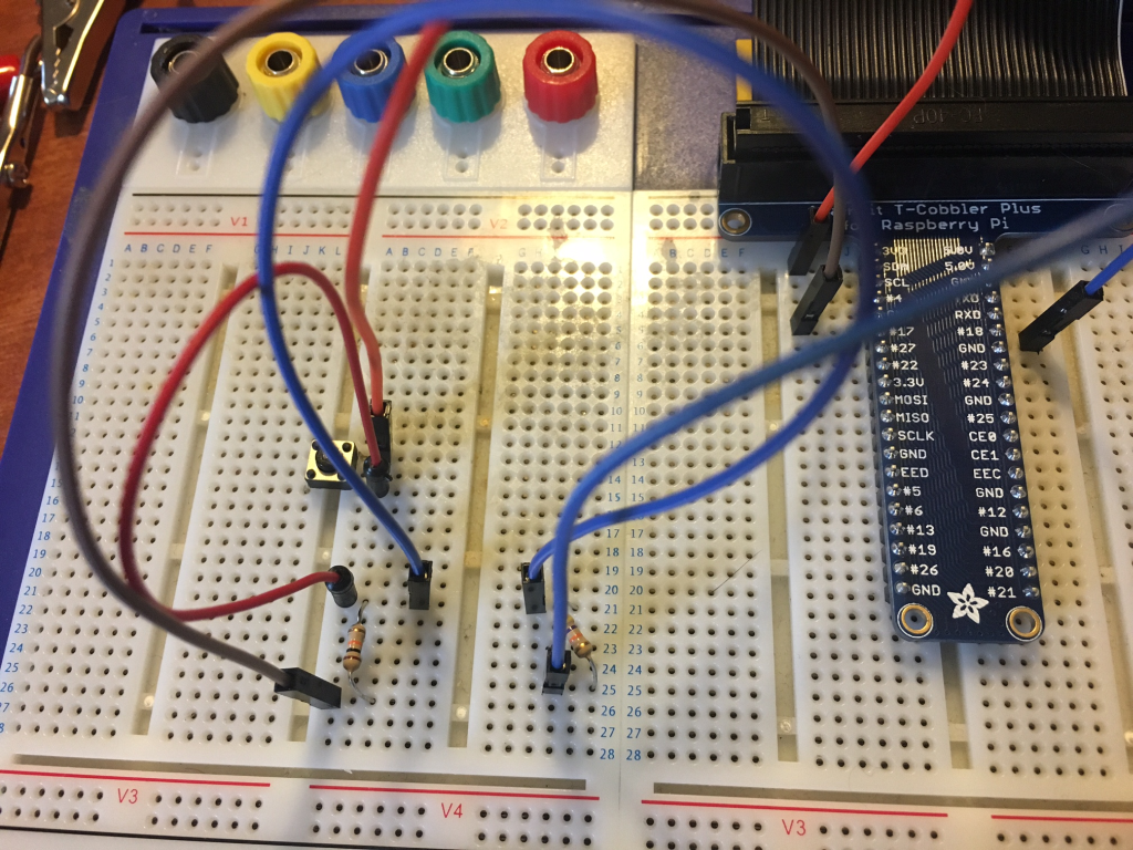
Now, let's do it with the raspberry pi (shown with the adafruit cobbler pinout prototyping device, but you can just connect it straight to the raspberry pi pins instead!).
![]()
So, we used the momentary switch again, and this time we've got a 22k Ohm resistor, and a 10k Ohm resistor. You'll need a breadboard to do it on, and female to male jump wires, plus male to male (or bare wires). In the video we use an LED and a different resistor in this part of the circuit, but that's just for visual impact! Don't bother with an LED in the final circuit. You can go ahead and learn about why the resistors are required here: https://www.cl.cam.ac.uk/projects/raspberrypi/tutorials/robot/buttons_and_switches/ but certainly don't use anything under 10k Ohm.
Here's a video of the circuit in action with the LED:
3.
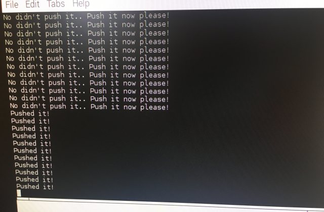
After building the circuit, let's see what we get from GPIO 18 when we push the button on the switch! So we need to write the following python testing code and run it:
import RPI.GPIO as GPIO
GPIO.setmode(GPIO.BOARD)
GPIO.setup(12, GPIO.IN)
try:
    while True:
             val = GPIO.input(12)
              if (val == True):
                   print("Pushed it!")
              else:
                   print("No didn't push it.. Push it now please!")
except KeyboardInterrupt:
      GPIO.cleanup()
Here's what we get when we run our code, and push the button!
![]()
Here's what the circuit looks like without the LED (you can zoom in to 1024*768 image)
![]()
4.
Finally we can add the OS command to shutdown into our python code:
import RPI.GPIO as GPIO
import os
GPIO.setmode(GPIO.BOARD)
GPIO.setup(12, GPIO.IN)
try:
    while True:
             val = GPIO.input(12)
              if (val == True):
                   print("Pushed it!")
                   os.system("sudo shutdown -h now")
              else:
                   print("No didn't push it.. Push it now please!")
except KeyboardInterrupt:
      GPIO.cleanup()
Don't forget to import the os library with import os!
Here's a video of what happens when we push that button! The raspberry pi shuts down safely using the operating system command. YAY!
CONCLUSION
So now the safe shutdown switch circuit and code is all ready to be deployed on the detection and deter devices! Obviously we don't bother printing anything in the final code, or use the except, since there isn't a keyboard present! We can go ahead and deploy this circuit on a small breadboard in the detection and deter devices, or we can turn it into a PCB. For instance, the article https://hackaday.com/2015/08/21/a-tale-of-two-browser-pcb-tools/ using browser tools to design and order your PCBs!
-
Notes for IR illuminators & enclosures & shutdown
09/28/2017 at 18:38 • 0 commentsSo I'm trialling these two pre-built IR illuminators:
- JCHENG SECURITY 4pcs High Power LED IR Array Illuminator IR Lamp Wide Angle for Night Vision CCTV and IP Camera £10.60
- ICAMI IR Illuminators 96 LED High Power Infrared LED Lights for Security Camera (White) £19.90
These are both 12v. So we will use the an optically isolated switching circuit to switch them on from the raspberry pi GPIO pins.We'll use
- Fairchild TIP122 NPN Darlington Pair, 5 A 100 V HFE:1000, 3-Pin TO-220 (£0.40)
- Isocom 4N25 DC Input Transistor Output Optocoupler, Through Hole, 6-Pin PDIP (£0.32)
- Resistors: 220 & 1K
ENCLOSURES
I've added tupperware type plastic containers to my list of example enclosures. Others seemed to have great success with using these outdoors! I've tried cutting holes in them which is fine using a dremel. Then I'm going to add glass lenses with seals in order for the camera to be able to get a good image. The glass lenses can go over the PIR too. And holes for cable in/out can be sealed using cable grommets. We can glue balsa wood to the bottom of these plastic contrainers, and screw standoffs into this wood for mounting the Raspberry Pi + other components.
The second addition I've made is halogen floodlight enclosures. In some cases these will be large enough to re-purpose (i.e. remove the lamp) to fit the raspberry pi's and other components inside. They already have a glass front, and PIR mount below. I'm not really sure if they will be large enough, but I'll have a try. You can get these already mounted on tripods too for quite low-cost. That would be quite handy.
The third addition is using CCTV security camera housing. Some of these are quite large, so may fit all of the elephant deter device components. If not, they could house the camera and PIR with the other components in a box. They also have a glass front which is helpful.
SAFE SHUTDOWN
So if users are coming to collect the detect and deter devices, they need to shut them down with
sudo shutdown -h now
to prevent any risk of corrupting the SD card. So we need a button to do this. Since they are not going to be coming along with HDMI cables, monitor, keyboard! So all we do with this circuit is connect the 3.3V out pin to a switch, put a 10kohm resistor between this and GND. Then we connect one of the GPIO pins as input, so if it gets HIGH we trigger the shutdown command. E.g.
import os
os.system("sudo shutdown -h now")
* update: the safe shutdown build instructions are here: https://hackaday.io/project/20448-elephant-ai/log/68015-buildinstructions-for-hardware-safe-shutdown-switch
-
#buildinstructions for hardware: solar charging circuit
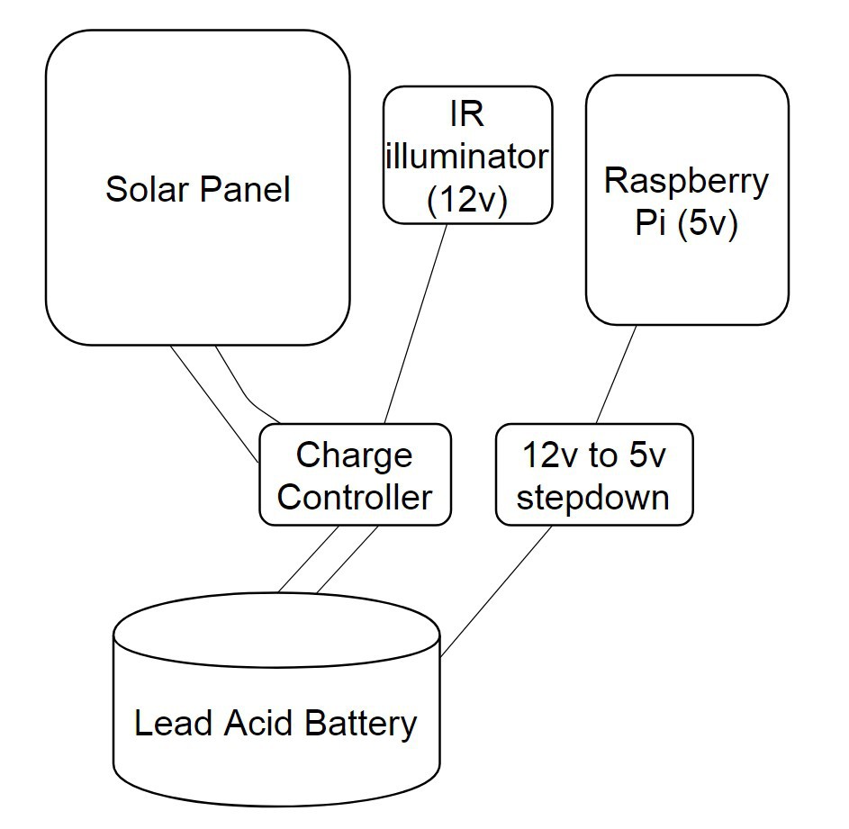
09/27/2017 at 17:52 • 0 commentsSo for this we need wires, connectors for the battery, a lead acid battery, a charge controller, and a solar panel!
WHICH BATTERY AND SOLAR PANEL SHOULD YOU USE?
From an earlier log, I investigated how to calculate the type of solar panel and battery required. This is dependent on local conditions.
SOLAR PANEL
What is the output power of the solar panel we need?
First we need to determine the total energy usage of the device in 24hr period (Watts). We can put this into the following equation as E. Whilst the output power of solar panel is P(solar). Let's supply the total time solar panel is in direct sun as 10hrs
P(solar) = E / (10*60*60)
BATTERY
Now how long do we need the battery to be able to deliver energy without solar charging? Obviously this is all kinda rough. We can go ahead and use a solar insulation map to determine more exact number of hours solar panel is in direct sun at a given time in year. So let's say anyway, we want the battery to deliver 48hrs of energy without any charging:
C(battery) = E / V*60*60
Where V = voltage we need, and C(battery) = storage capacity in Ah, and E = energy usage of device.
COMPONENTS USED FOR THIS EXAMPLE BUILD
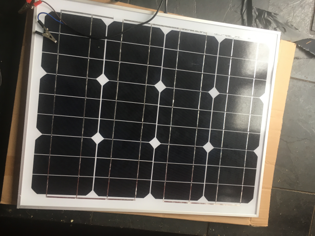
- 30W Solar Panel
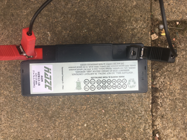
- 12V 17.8Ah Lead Acid Battery
- 18 AWG Gauge Electrical Wire (black and red)
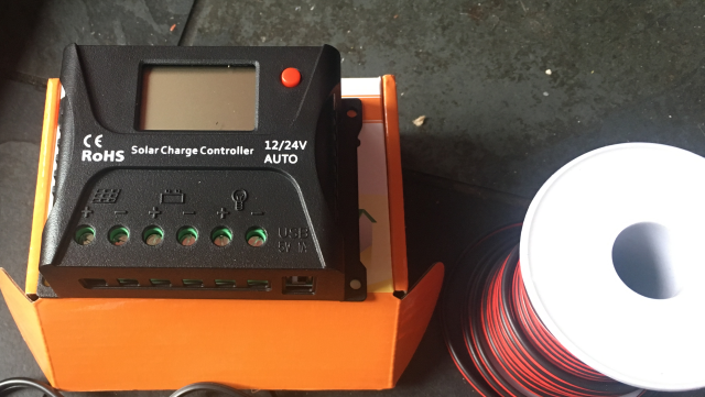
- HQST 10 Amp 10A PWM Smart Solar Charge Controller 12V/24V Solar Panel Battery Regulator with LCD Display USB Port (£16)
- Multimeter
- Wire cutters
- Wires with crocodile clips and bare ends
- Screwdrivers
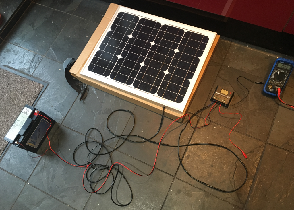
BUILD INSTRUCTIONS
1. Assemble the components
![]()
![]()
![]()
* the big clips on the battery are for charging from AC. You'll need to charge your battery in this way before you deploy it.
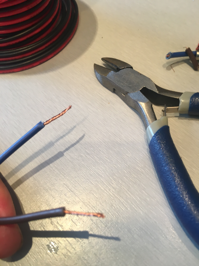
2.
Cut the wires. The charge controller takes bare wire ends, so you need to strip the wires. First off I cut two wires (red and black) to an appropriate length for connecting the battery to the charge controller. I stripped these on both ends. Then I cut off the crocodile clips from the wires that are attached to the solar panel, and stripped them, ready to attach to the charge controller. Make sure you are aware which is -ve and +ve coming from the solar panel! In my case it was brown +ve and blue for -ve. You can see the layout in the following diagram:
![]()
![]()
![]()
Above you can see the outputs from the back of the solar panel. Remember to verify which is +ve and which is -ve!
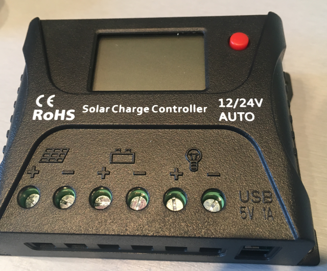
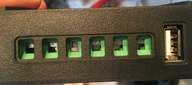
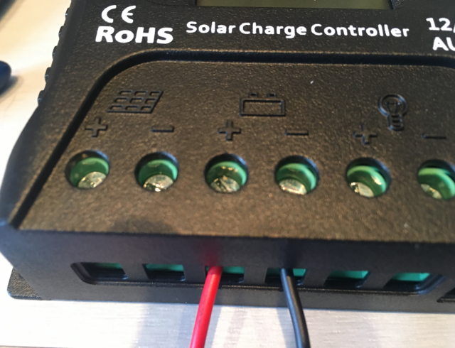
3.
Now all the wires are ready, we can connect the other components of the solar charging circuit to the charge controller. The inputs are marked. On mine, I have solar panel input, battery connection, 12v output, and a USB 5v output. Unscrew the top screws so you can push the wires into the slots, then screw them up again!
![]()
![]()
![]()
Above you can see the +ve and -ve (red and black) wires for the battery connected to the charge controller. In the photo below you can see everything is connected! We are all ready to go! I've uploaded it sized so you can zoom in!
![]()
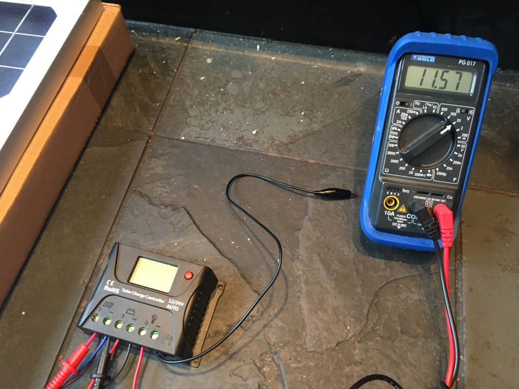
4.
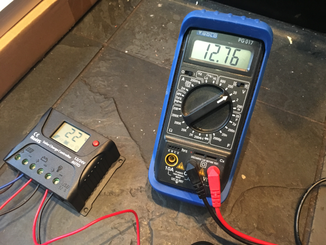
Now it's a good idea to do some checking using the multimeter. First I checked the voltage coming out of the solar panel. This was just by connecting the multimeter to intercept the inputs from the solar panel to the charge controller. I got around 12v as expected.
![]()
Next, I wanted to see the current coming out of the solar panel. This is quite fun, because you can see it change according to how much light is hitting the solar panel! You can see this in the video below when I turn the indoor light on and off (it was raining so I couldn't do it outside):
So everything seems ok with the solar panel! Let's see what's going on with the charge controller. I won't go into details for this specific controller, as it would be unlikely you will use the same. In the video below we can see what the LCD display gives us when the entire solar charging circuit is up and running. Note that E0 = error code zero (i.e. no errors). It gives voltage, battery temperature, and % of charge.
5.
Ok, so let's check the outputs from the charge controller. With this model we have a 12v and a 5v USB. I checked the 12v output by connecting wires with bare ends on one end to the charge controller, and crocodile clips on the other, to my multimeter. You could test the USB C output by checking the power pins (the pin outs are listed here https://en.wikipedia.org/wiki/USB-C#Connector_pinouts) but honestly it would be rather excessive, and time-consuming if you don't have a USB cable tester. But hey, if there's time and you don't want to risk damaging a raspberry pi then you could do it! Anyway, we got 12.76v output from that 12v output on the charge controller.
![]()
In the elephantAI system, we'd use the 12v to supply power for the IR illumination on the detection devices, and the audio amplifier on the deter devices. This particular model has a USB C connector outputting 5v. So, that can power the Raspberry Pi components. But in other models, you may only get a 12v output, so will have to step this down to 5v to power the Raspberry Pi components of the ElephantAI.
The easiest way to do this is to google "DC-DC Converter Step Down Module 12V to 5V Micro USB Output". You can pick these up for £6-£12 on amazon or ebay. Failing that you can look for a a converter "car power supply 12v to 5v". But these only have +ve and -ve outputs. So you will have to hook these wires up to a micro USB connector. There's a tutorial for doing that here: https://geekhack.org/index.php?topic=44924.0
You can also build your own circuit, perhaps using an IC 7805 (Voltage Regulator IC), heatsink, etc. I'll try to find time to show how to build this.
So, that's it! The solar charging circuit is all ready to go once it has a waterproof enclosure for the battery, and a mount for the solar panel!
CONCLUSION
You can use the batteries, charge controllers, and solar panels that are available easily and cheaply to you for building the solar charging circuit. As mentioned at the start, you can decide on the battery capacity and the solar panel type depending on local conditions. You certainly don't have to use the same components as I have done! You can build your own charge controller of course, it would be cheaper, I'll try to outline a build if I have time!
-
#buildinstructions for hardware: elephant deter devices
09/24/2017 at 18:51 • 0 commentsINTRODUCTION
The elephant detection component of the system will communicate with these using Bluetooth (100m supposed range). We can go ahead and power them using the same solar/lead acid battery component that we use for the elephant detection components, or if they are isolated (e.g. >5m away) we will have to give them their own solar/lead acid battery components. At present if they receive a message having a deter=yes they will go ahead and play audio files of bee sounds. It will be a pseudo-random choice of bee audio file, to prevent elephant habituation to a single bee sound.
For these the primary parts are:
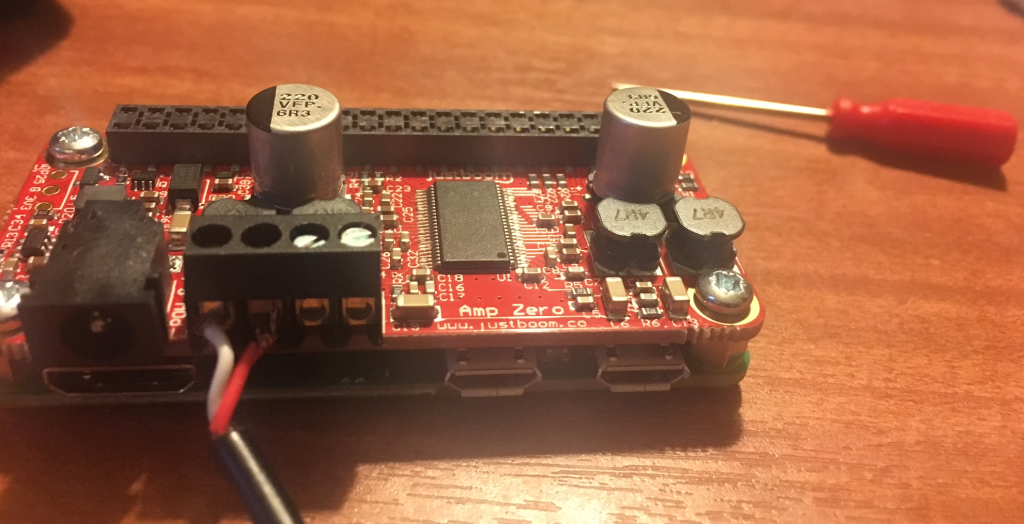
1. JustBoom Amp Zero pHAT for the Raspberry Pi Zero (£24)
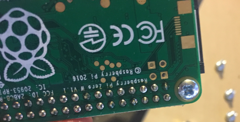
2. Raspberry Pi Zero W with Soldered Header (£14)
of course you can solder them on yourself, which would mean a cost of £9 + headers e.g. £1
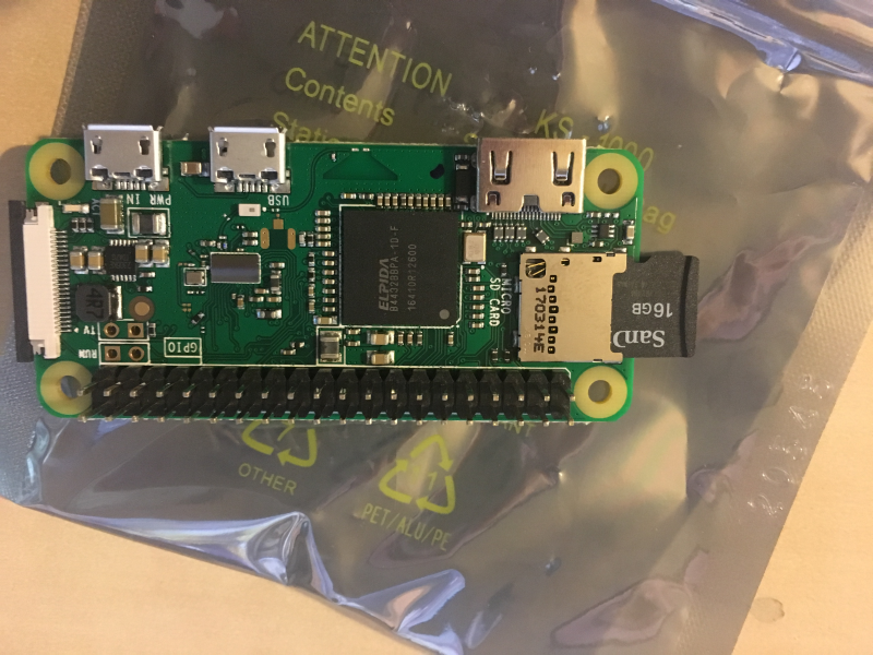
3. micro SD card with operating system installed. I've used 16GB with NOOBS pre-installed (£9.99)
4. Power supply e.g. solar and lead acid battery
5. Speakers x2; it's flexible e.g. old hifi speakers, old external laptop/PC speakers, etc. I'm using two waterproof 5V 4Ohm speakers from ebay (£11 each)
ATTACHING THE AMP ZERO TO THE PI ZERO W
First we need to attach the amp zero HAT to the pi zero! This is really easy and you just need a tiny phillips screwdriver to do it. There are 4x metal spacers (well they look like nuts really), and 8x metal bolts. There's a full guide here https://www.justboom.co/start/set-up-justboom-amp-zero-phat-and-case/ but I will summarise the instructions too:
1. Put you SD card into the pi zero card reader slot!
![]()
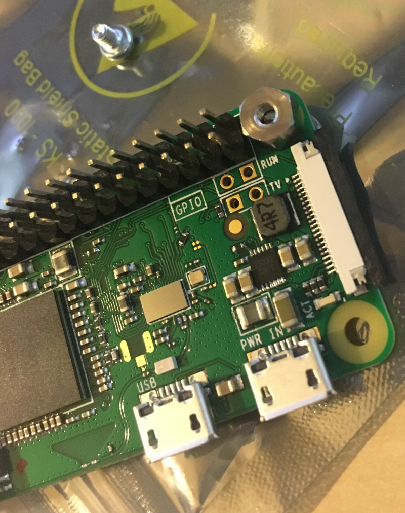
2. Fit your nuts/spacers and secure them to the pi zero with bolts
![]()
![]()
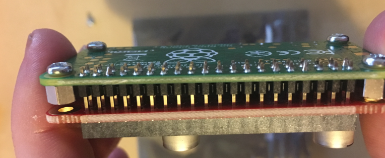
3. Gently attach the Amp Zero female header to the Pi Zero male header. Push down to do this.
![]()
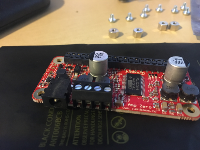
Here's the Amp Zero prior to attachment. You can see the female header at the back. And the 4x speaker outputs + 3.5mm jack at the front.
![]()
4. Screw in your last 4x nuts to the holes in amp zero - so securing the two devices together
5. The Amp Zero power usage configurations (for different speakers) are here: https://www.justboom.co/technical-guides/amp-boards-power-specifications/ remember that the Pi Zero is back powered from the Amp Zero (so you don't need to power it)
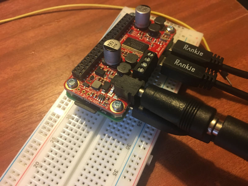
6. For testing, I'm using a 24 Volt 3.75 Amp 90 Watt Power Supply. You can go ahead and connect your keyboard, mouse, and monitor to the Pi Zero now. And your power supply! Then we are ready for the next stage. Remember that Pi Zero has a mini HDMI socket. So you'll need a mini HDMI to HDMI adaptor. It also has micro USB sockets for keyboard/mouse, so you'll need adaptors.
7. I think it's best to put the setup (pi zero + amp zero) into a box at this stage! After you've connected the keyboard, mouse, power, and the mini HDMI, it kind of keeps getting dragged about by the cables. Mine fell on the floor several times. And I ended up handling it so much it was destroyed -by ESD (i.e. static discharge) I think :-( I
![]()
TESTING AND SETTING UP SOFTWARE, ADDING SPEAKERS
[not completed section yet.......]
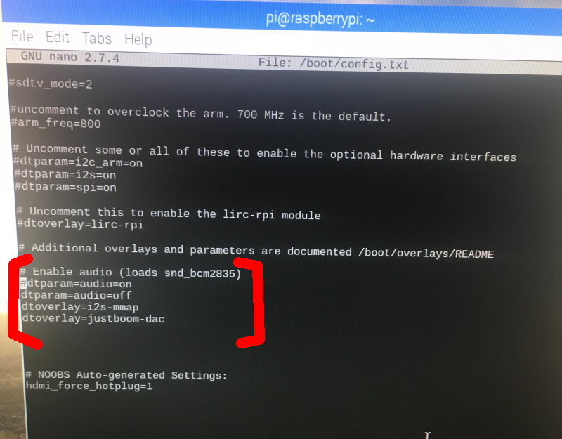
8. Now we need to configure Raspian OS to use the Amp Zero for sound output. First open the config.txt file with the command on your raspberry pi:
sudo nano /boot/config.txtNow scroll down the file until you reach the line:
dtparam=audio=onYou should comment this out with #, so you will have:
#dtparam=audio=onNow, go ahead and add these new config instructions:
dtparam=audio=off dtoverlay=i2s-mmap dtoverlay=justboom-dac![]()
*Check the Just Boom website to confirm these config commands are correct! https://www.justboom.co/software/configure-justboom-with-raspbian/
9.
Now we need some speakers! You can decide on which speaker to use according to the power requirements you are able to fulfil, and what you can get cheaply!
You can buy waterproof speakers, or you can water-proof some yourself! You can even build your own speaker cabinet if you want! I just purchased some cheap waterproof speakers from ebay for £11 each. My speakers are 5V 4Ohm 'Weatherproof Communication Extension Speaker B185' .
First of all I cut off the 3.5mm jack that came on the end of the speaker input cables, and stripped the wires to attach to the speaker output terminals on the Amp Zero.
Then I attached the wires to the speaker output terminals of the Amp Zero. There are four output blocks. From the left: outputs 1 and 2 for the first speaker, outputs 3 and 4 for the second speaker. The -ve output is first, then the +ve output, same again for the second speaker. See image below:
![]()
![]()
10.
Now we can get to playing the bee sounds and/or tiger sounds/other sounds!
I downloaded wav files from freesound.org. The audio files here are licensed under Creative Commons Attribution 3.0 Unported (CC BY 3.0) https://creativecommons.org/licenses/by/3.0/
So the bee sounds I used are:
bees1.wav http://freesound.org/people/Benboncan/sounds/73370/ attributed to user: http://freesound.org/people/Benboncan/ | licensed under https://creativecommons.org/licenses/by/3.0/
It might be a great idea to record sounds of local bees that are known to the elephants, and use these instead for your system! The same with local tigers, and perhaps local people shouting too!
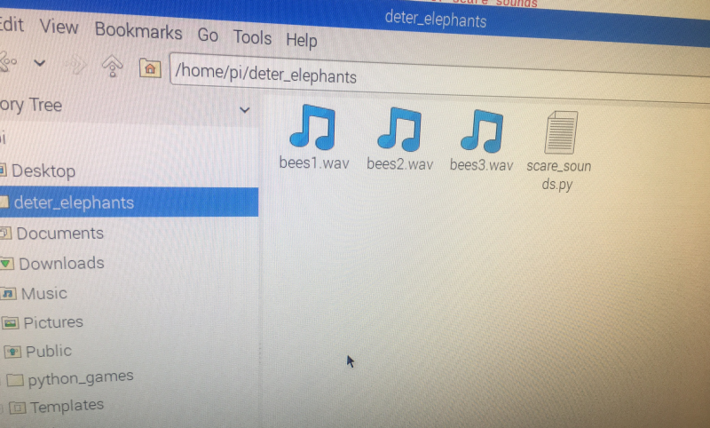
I've gone ahead and saved these to a directory called deter_elephants
![]()
The bee sounds/scare_sounds are played using aplay - a linux command line player for the ALSA soundcard driver (http://manpages.ubuntu.com/manpages/trusty/man1/aplay.1.html)
The following code can be used to play them:
import time
import random
import os
scare_sounds = ['aplay bees1.wav', 'aplay bees2.wav', 'aplay bees3.wav']
i = 0
while i < 4:
    i = i+1
    to_play = random.choice(scare_sounds)
    print(to_play) #debug
    os.system(to_play)
    time.sleep(1)
We import time, random and os. We execute aplay use os.system(aplay filename). The command to execute on command line (i.e. "aplay") and the file to pass to aplay (e.g. "bees1.wav") are all stored in the scare_sounds list.
So random.choice will pseudo-randomly pick a list item and put it into to_play variable (e.g. "aplay bees3.wav") and then os.system will execute this.
The while loop is set to run while i is less than 4. You can adjust this to how long you want to continue playing the scare_sounds. It depends on the length of your scare_sound audio files and how long you think it will take to deter the elephants! So that needs some field research to determine!
So we've got that python code saved as scare_sounds.py into deter_elephants directory, and the bee%.wav files saved into the deter_elephants directory! Now we can go ahead and run it!
Here are the sounds of the bees after we run that code!
COMMUNICATING WITH THE DETER DEVICE VIA BLUETOOTH
11. We can use the PyBluez library https://github.com/karulis/pybluez "python extension module allowing access to system Bluetooth resources [free license update details] and http://www.bluez.org/about/ Bluez "official linux bluetooth protocol stack" to do this [unknown license update details]. Or we can use python sockets which support Bluetooth instead (for python 3.3.x that is).
Let me say in advance! Now is the time to pair your deter device with the detection device so they can communicate via Bluetooth! It's easy in the GUI. Just head to the Bluetooth icon on the top right of screen for your deter device and select add device (the other device i.e. detection device should be set via its Bluetooth GUI menu to discoverable when you do this).
First, make sure serial profile is loaded:
sudo sdptool add SPWe can have two scenarios:
A. Deter device constantly acts as server, waiting for a deter=yes message from the detection devices. The detection device acts as client. Here we can't report back to the deter devices if we performed a deter successfully or not.
B. Deter devices acts as server. Detection device acts as client. Once the deter device has received a deter=yes message, it will run its scare code, then it will switch to client. The detection device switched to server after it sent the deter=yes message, and will now be listening for a confirmation message back from the deter device!
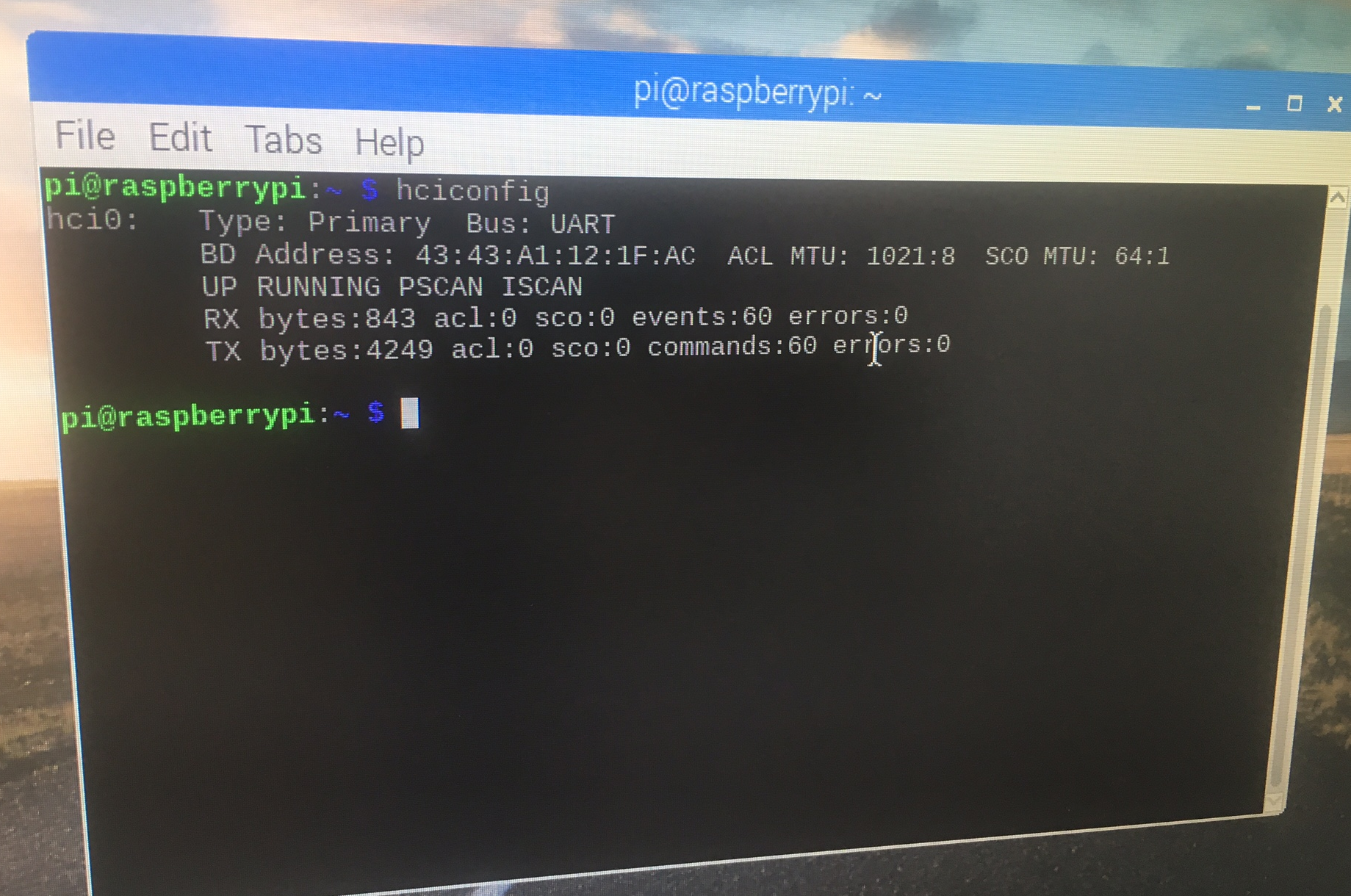
Regardless of scenario deployed, we need to get a MAC address for the Bluetooth adaptor on the respective devices.
We can use the following command to get the MAC address:
hciconfig
And we should get back something like 43:43:A1:12:1F:AC (which is what I got). You shouldn't get something like AA:AA:AA:AA:AA:AA. That is not good!
![]()
Ok, so we are going to use the second scenario, since we want the deter device to report back to the detection device if it performed a deter. First, let's do the test code for using native python sockets. It's similar to our code for communicating between the detection devices using Ethernet!
First for the server, so this is what the deter device is running:
import socket
hostMACAddress = '00:1f:e1:dd:09:3d'
# The MAC address of a Bluetooth adapter on the server.
# Which we got using hciconfig
port = 9
# anything that isn't in use
backlog = 1
size = 1024
s = socket.socket(socket.AF_BLUETOOTH, socket.SOCK_STREAM, socket.BTPROTO_RFCOMM)
s.bind((hostMACAddress,port))
s.listen(backlog)
try:
    client, address = s.accept()
    while 1:
        data = client.recv(size)
        if data:
            print(data)
            client.send(data)
        # echo back to client that we got the data
except:
    print("Closing socket")
    client.close()
    s.close()
if data == "yes_audio":
    deter = 1
# if the data sent from the client (detection device) was "yes_audio" we
# set deter to 1
Secondly for the client (detection device):
import socket
message = "yes_audio"
serverMACAddress = '00:1f:e1:dd:08:3d'
port = 9
s = socket.socket(socket.AF_BLUETOOTH, socket.SOCK_STREAM, socket.BTPROTO_RFCOMM)
s.connect((serverMACAddress,port))
while 1:
    s.send(bytes(message, 'UTF-8'))
s.close()
Now we switch the detection device to the server:
import socket
hostMACAddress = '00:1f:e1:dd:08:3d'
# The MAC address of a Bluetooth adapter on the server. Which we got using hciconfig
port = 9
# anything that isn't in use
backlog = 1
size = 1024
s = socket.socket(socket.AF_BLUETOOTH, socket.SOCK_STREAM, socket.BTPROTO_RFCOMM)
s.bind((hostMACAddress,port))
s.listen(backlog)
try:
    client, address = s.accept()
    while 1:
        data = client.recv(size)
        if data:
            print(data)
            client.send(data)
except:
    print("Closing socket")
    client.close()
    s.close()
if data == "done":
    deter_done = 1
else:
        deter_done = 0
# so if the data we got back from the deter device was "done" we know it did the deter, else we can assume it failed
Now we switch the deter device to client, so it can send the "done" message to the server (detection device):
import socket
message = "done"
serverMACAddress = '00:1f:e1:dd:08:3d'
port = 9
s = socket.socket(socket.AF_BLUETOOTH, socket.SOCK_STREAM, socket.BTPROTO_RFCOMM)
s.connect((serverMACAddress,port))
while 1:
    s.send(bytes(message, 'UTF-8'))
s.close()
Now, let's do test code for doing this with PyBluez instead. This is best for doing device discovery and Bluetooth service advertisements, and if you don't have python 3.3.x.
First for the server, so this is what the deter device is running:
import bluetooth
hostMACAddress = '00:1f:e1:dd:08:3d'
port = 9
backlog = 1
size = 1024
s = bluetooth.BluetoothSocket(bluetooth.RFCOMM)
s.bind((hostMACAddress, port))
s.listen(backlog)
try:
    client, clientInfo = s.accept()
    while 1:
        data = client.recv(size)
        if data:
            print(data)
            client.send(data)
        # echo back to client so it knows we got the data
except:
    print("Closing socket")
    client.close()
    s.close()
if data == "yes_audio":
    deter = 1
# if the data sent from the client (detection device) was "yes_audio" we
# set deter to 1
Secondly for the client (detection device):
import bluetooth
message = "yes_audio"
serverMACAddress = '00:1f:e1:dd:08:3d'
port = 9
s = bluetooth.BluetoothSocket(bluetooth.RFCOMM)
s.connect((serverMACAddress, port))
while 1:
    s.send(message)
sock.close()
Ok, so I won't do the others, it's just the same thing, but with a different way of setting the sockets.
[video]
12. What kind of data is the detection device going to be sending?
Well it was intended to send a JSON file as a string. We looked at making these files for each detection alert in this log https://hackaday.io/project/20448-elephant-ai/log/67563-messaging-formats-example-of-json-alert-message-file . So in this scenario, the deter device is going to parse that string for:
"deter" : {
    "deterdone" : "no",
    "deteraudio" : "no",
    "deterphysical" : "no"
And if it gets deteraudio as having "yes" after the ":" then it can go ahead and run the code in part 10. Then the server (deter device) will send a modified JSON back to the client as a string with the deterdone "no" changed to "yes".
Now we do need two of these things! We need the detection device to send data telling the deter device to perform the deter (i.e. play scare_sounds), and we do need the deter device to send data to the detection device it has run this code for the time we've specified. It's important for the detection device to know if deter has occurred, since this information is required by the system users. But do we need to bother with sending entire JSON messages back and forth? I'm not sure there's any point!
So we can just work like this:
- Deter device (server) listens on socket
- Detection device (client) sends data "yes_audio" to deter device (server) if elephant spotted and wants a deter done
- Deter device (server) runs the code to randomly play the audio files. Then once loop completes, it sends data "yes_done" back to detection device (client). If something went wrong it would send data back "no" to detection device (client)
Which is a lot easier!
13 Here we go with code to both receive the message from the detection device, play the sounds of bees, and send a message back. Then wait again for a message!
# DETER DEVICE
# this is test code for getting a message via bluetooth from the detection device, and
# going ahead and playing scare sounds
import socket
import time
import os
import random
hostMACaddress = 'xxx'
port = 9
backlog = 1
size = 1024
s = socket.socket(socket.AF_BLUETOOTH, socket.SOCK_STREAM, socket.BTPROTO_RFCOMM)
s.bind((hostMACaddress, port))
s.listen(backlog)
print("We are waiting for a message from the detection device to arrive via bluetooth!")
try:
    client, address = s.accept()
    data = client.recv(size)
    if data:
        print(data)
        client.send(data)
        #echo back
except:
    print("closing the socket")
    client.close()
    s.close()
message = str(data)
#convert the data received to a string
print(message)
if message == "b'yes_audio'":
    print("play scare sounds now")
    time.sleep(3)
    scare_sounds = ['aplay bees1.wav', 'aplay bees2.wav', aplay bees3.wav']
    i = 0
    while i <10:
        i = i+1
        to_play = random.choice(scare_sounds)
        print(to_play)
        os.system(to_play)
print("Finished scare. Now can message detection device, and await another message from it")
Ok, let's go ahead and see that in action with this video. Warning! Don't play this when you're near to a beehive!!
14.
Now we need our code to run on startup! So when the Pi Zero comprising the deter device has power and boots, we execute our python code!
We need to edit /etc/rc.local
So edit with command:
sudo nano /etc/rc.localThen add the following:
python /home/pi/deter_elephants/deter_device_code.py &The ampersand (&) will allow the command to run in a separate process, so raspberry pi booting can continue with the process running.
15.
Now all the hardware and software is completed, we can put our elephant deter devices into a waterproof housing.
We need to drill holes into the housing for +ve and -ve power wires from the solar charging circuit/battery. And we need to drill holes for the four speaker output cables from the Amp Zero.
I mounted my speakers on the top of the housing by drilling 4 other holes and using nuts and bolts!
There are many different solutions to housings and speakers!
Elephant AI
a system to prevent human-elephant conflict by detecting elephants using machine vision, and warning humans and/or repelling elephants