 Arnov Sharma
-
1MAIN BOARD ASSEMBLY PROCESS
![]()
![]()
![]()
![]()
![]()
![]()
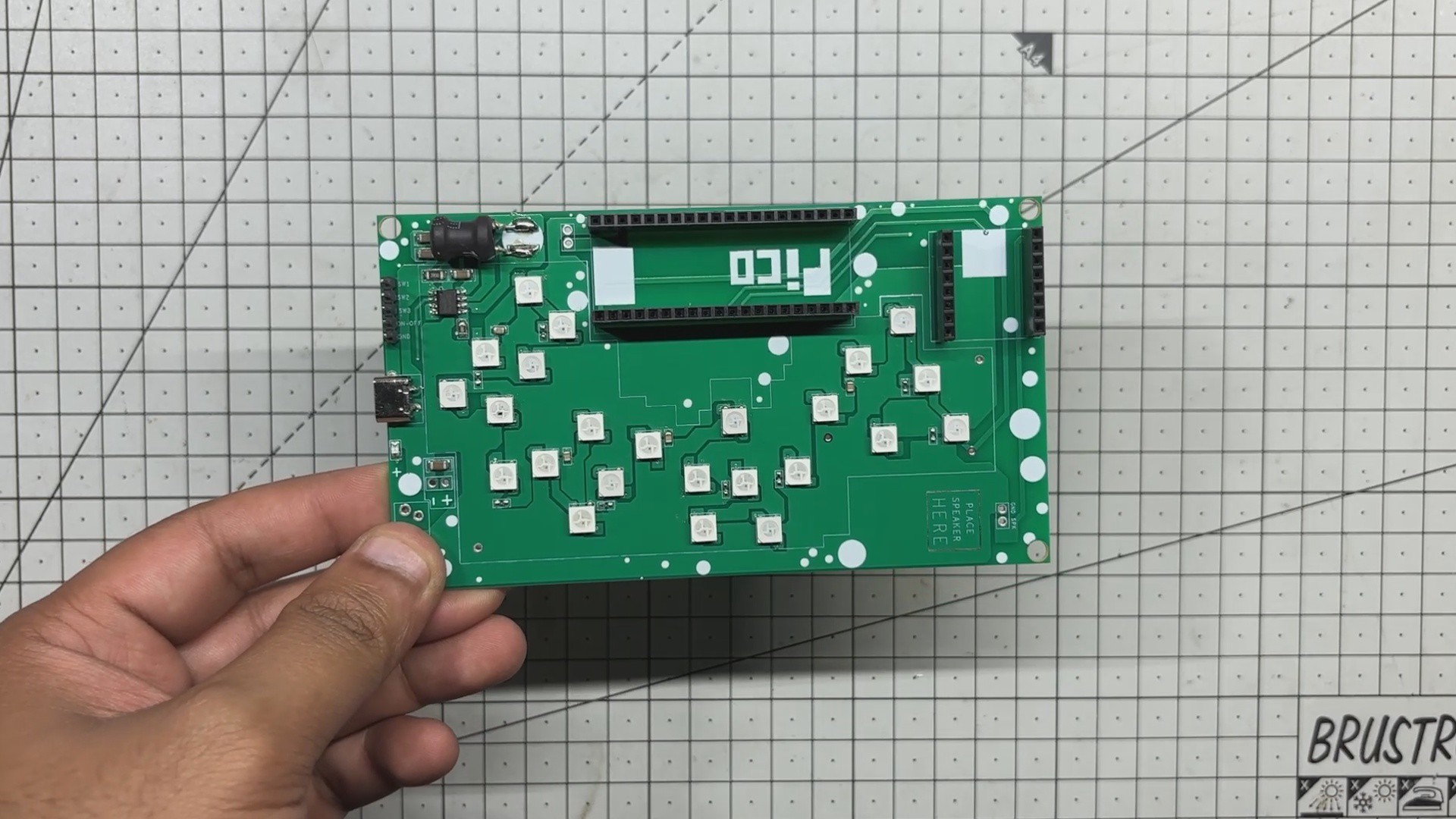
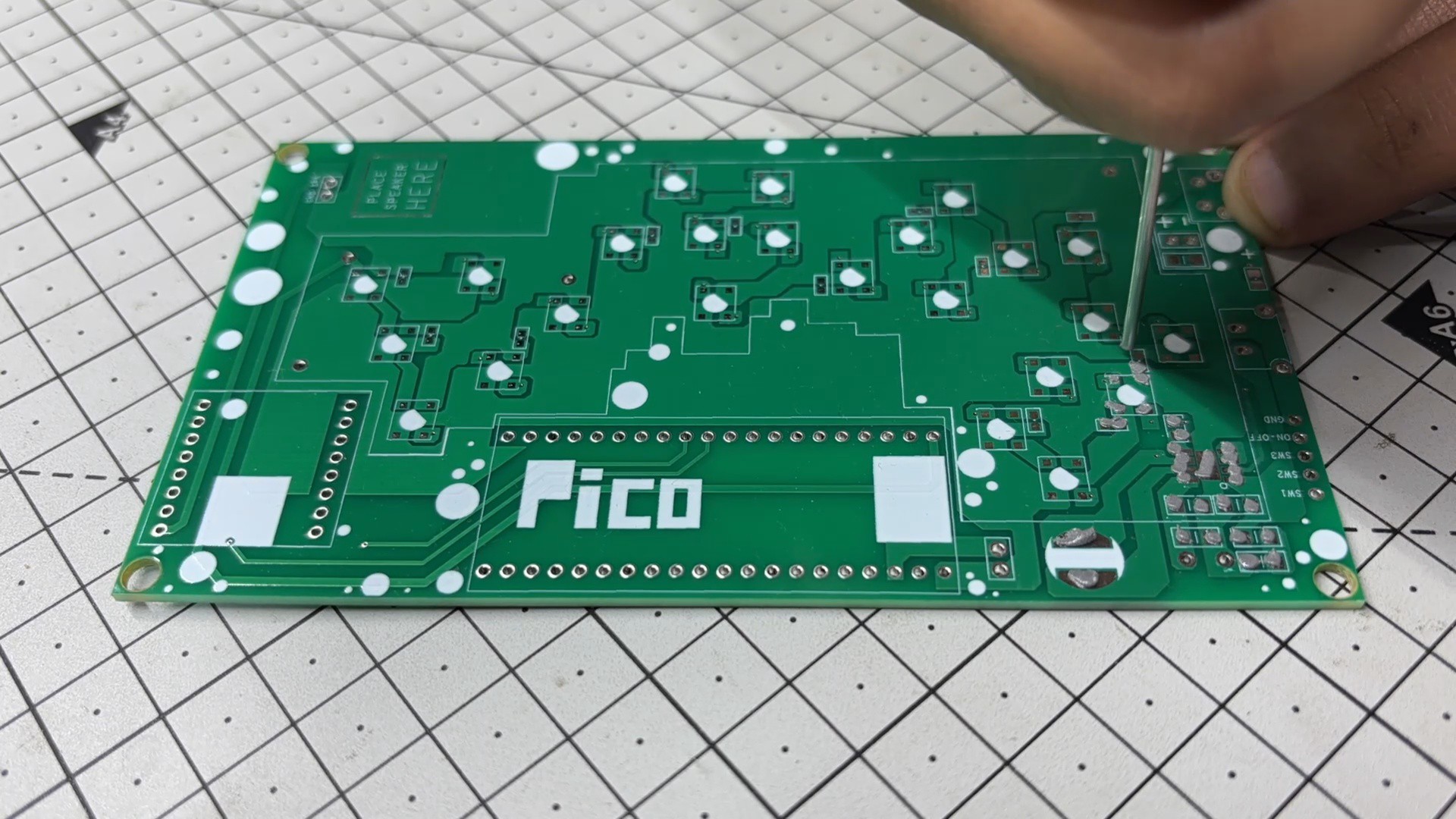
- We begin assembling the main board by applying solder paste to each SMD pad using a dispensing needle. For this build, we’re using 63/37 Sn/Pb solder paste, which has a melting point of around 200°C.
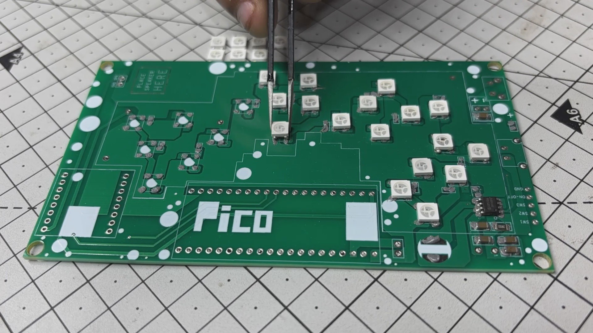
- Next comes the pick-and-place stage, where each surface-mount component, which includes RGB LEDs, the IP5306 power management IC, capacitors, and resistors, are carefully positioned using ESD-safe tweezers.
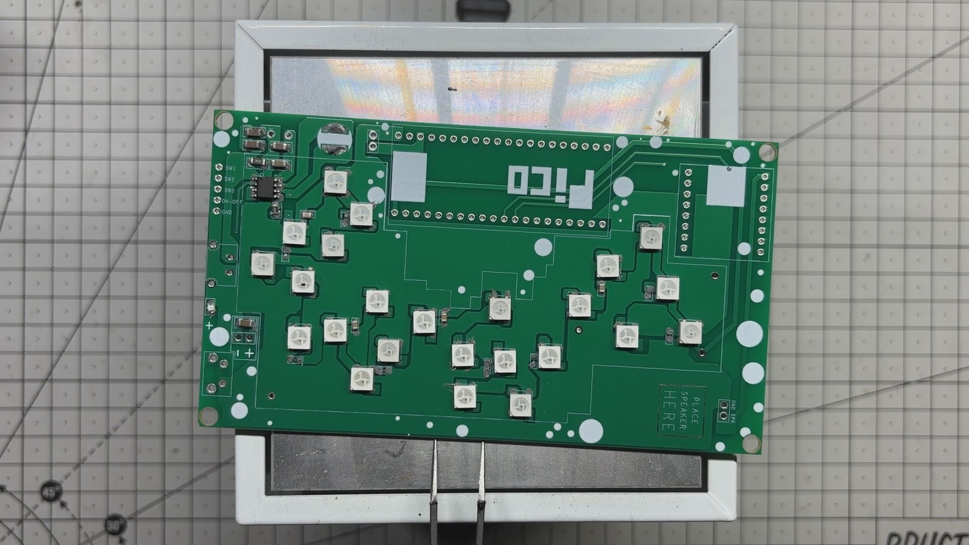
- Once all components are in place, the PCB is transferred to a reflow hotplate. The board is heated from below until it reaches the solder paste’s melting temperature. At that point, the solder melts and solidifies, locking all SMD components securely in place.
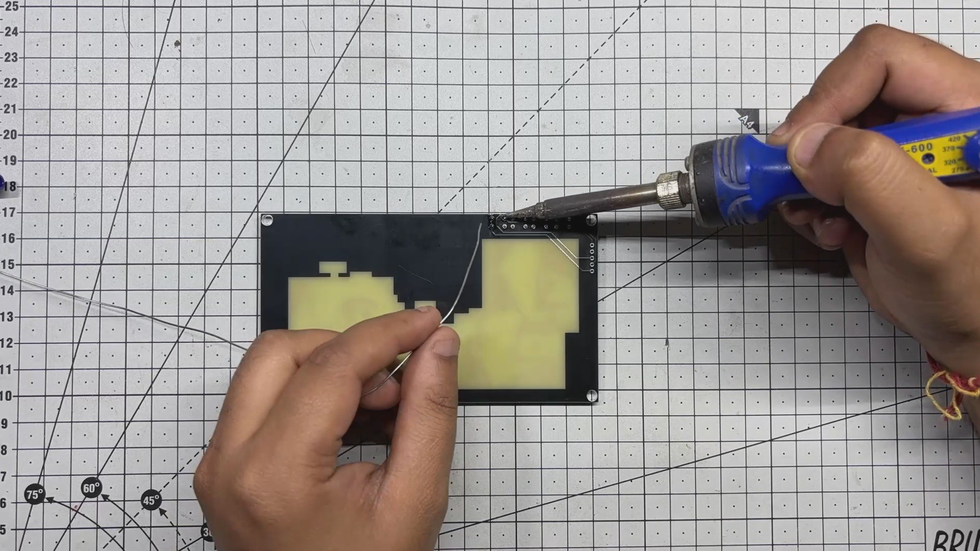
- With the surface-mount process complete, we move on to the through-hole components. Female header pins for the Raspberry Pi Pico and DFPlayer Mini, a USB Type-C port, male header pins, and an inductor are added from the top side of the board.
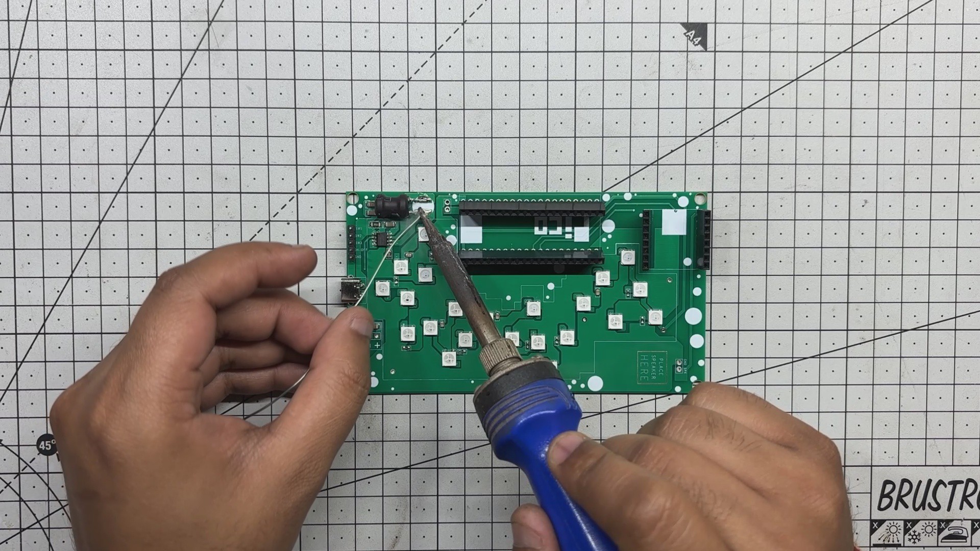
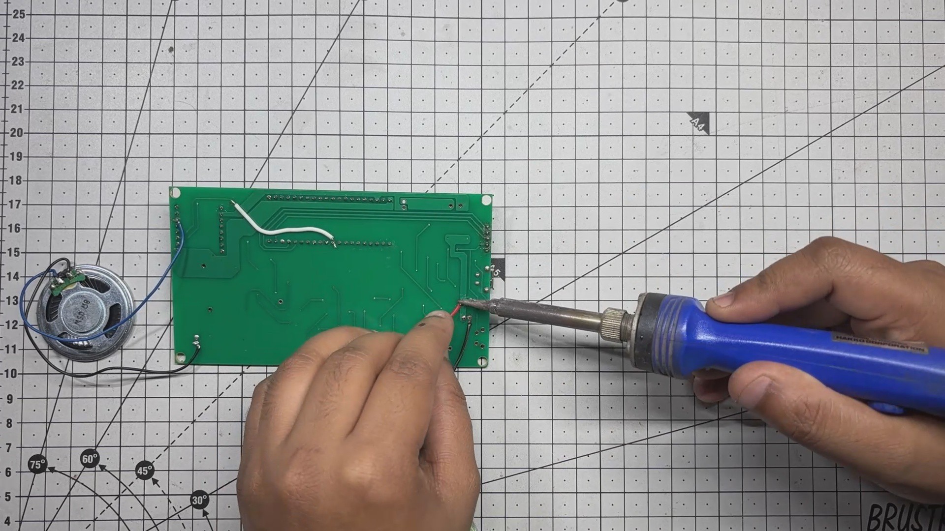
- The PCB is then flipped, and all through-hole pads are soldered manually using a soldering iron to ensure strong mechanical and electrical connections.
- Finally, the Raspberry Pi Pico and DFPlayer Mini are mounted onto their respective headers, marking the completion of the assembly process.
-
2ART LAYER ASSEMBLY PROCESS
![]()
![]()
![]()
![]()
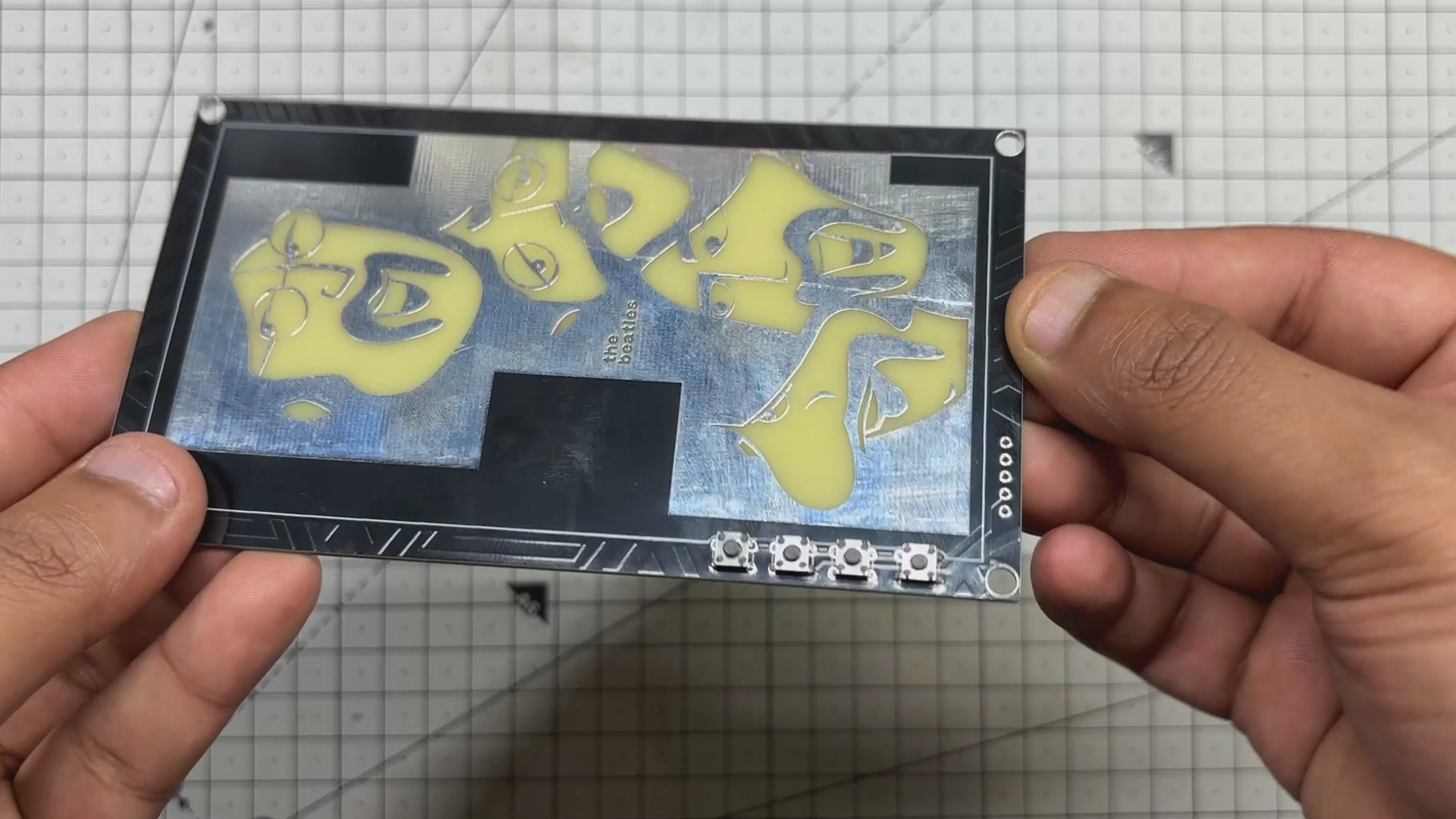
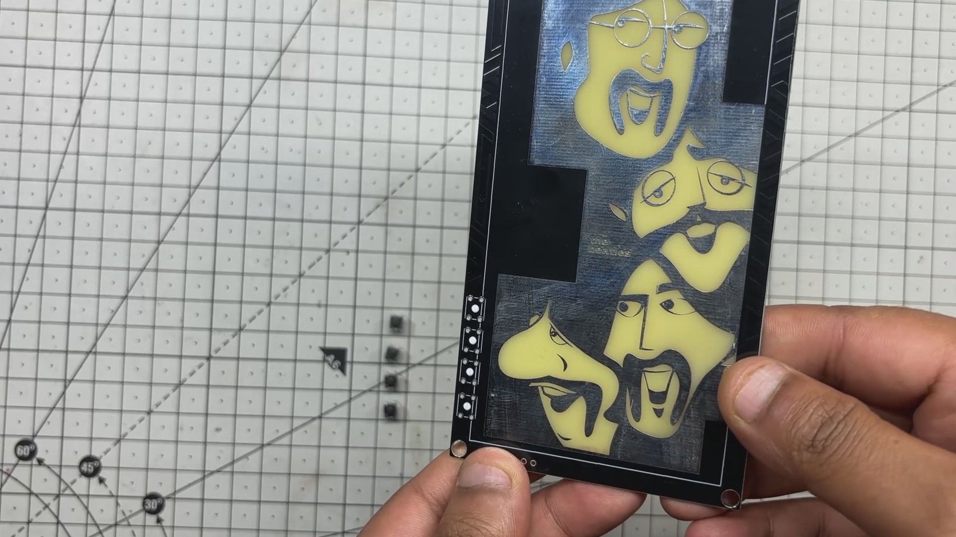
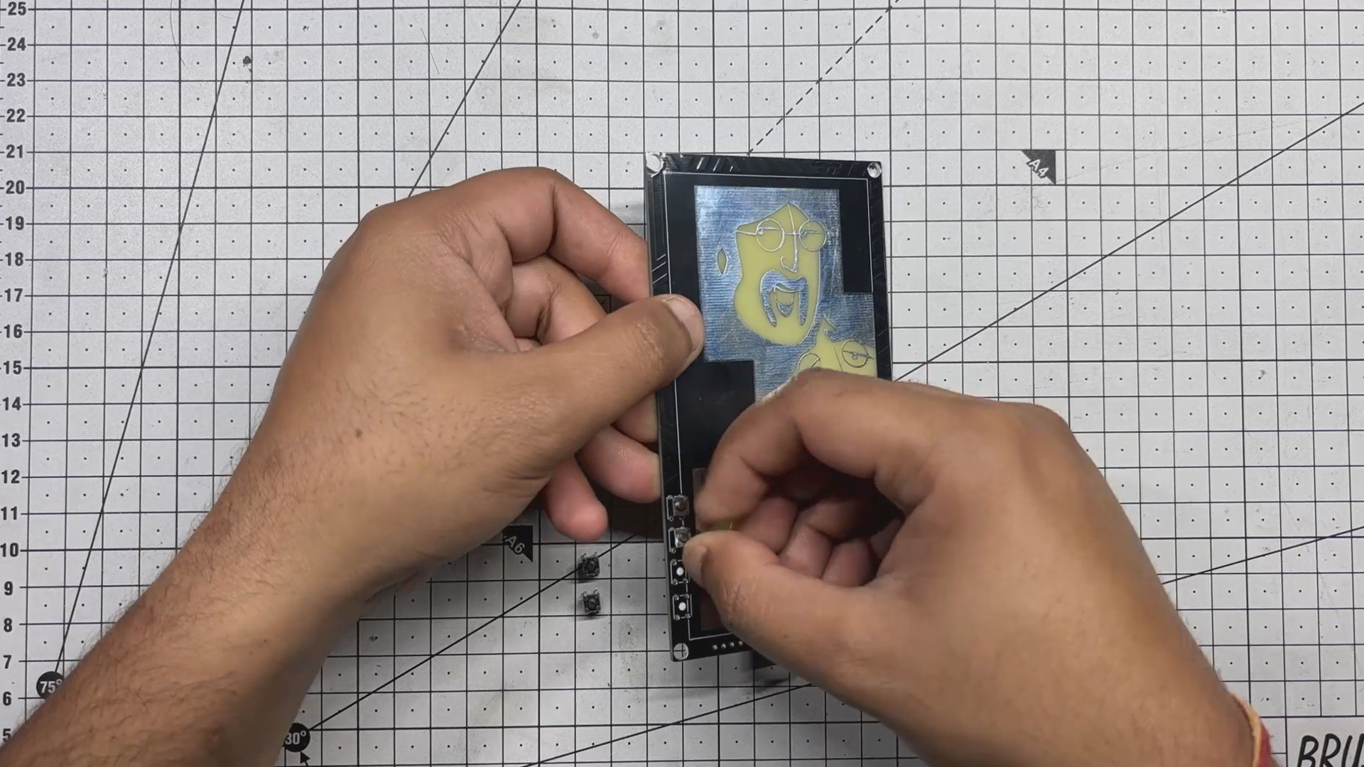
The front board contains four through-hole 4×4 tactile push buttons. Each button is placed carefully into its designated position on the PCB. Once aligned, the board is flipped over and all the pads are soldered securely, locking the buttons in place.
-
3SPEAKER ASSEMBLY
![]()
![]()
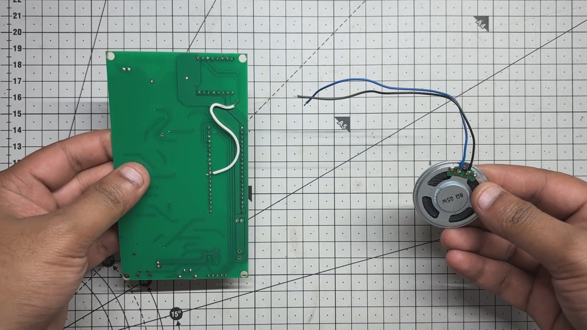
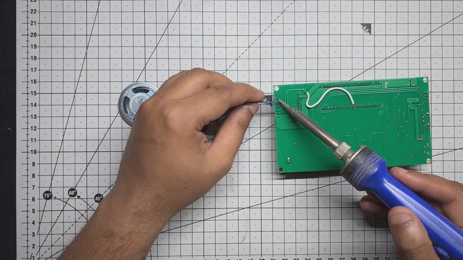
Next comes the speaker assembly process. It begins by soldering the speaker’s positive terminal to the Speaker 1 pin on the DFPlayer Mini, while the Speaker ground (GND) terminal is connected to the Speaker 2 terminal of DFplayer.
This simple wiring setup completes the audio path.
-
4POWER SOURCE
![]()
![]()
![]()
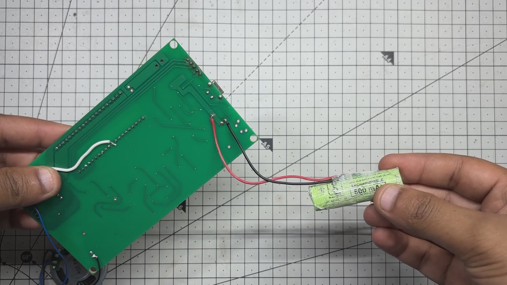
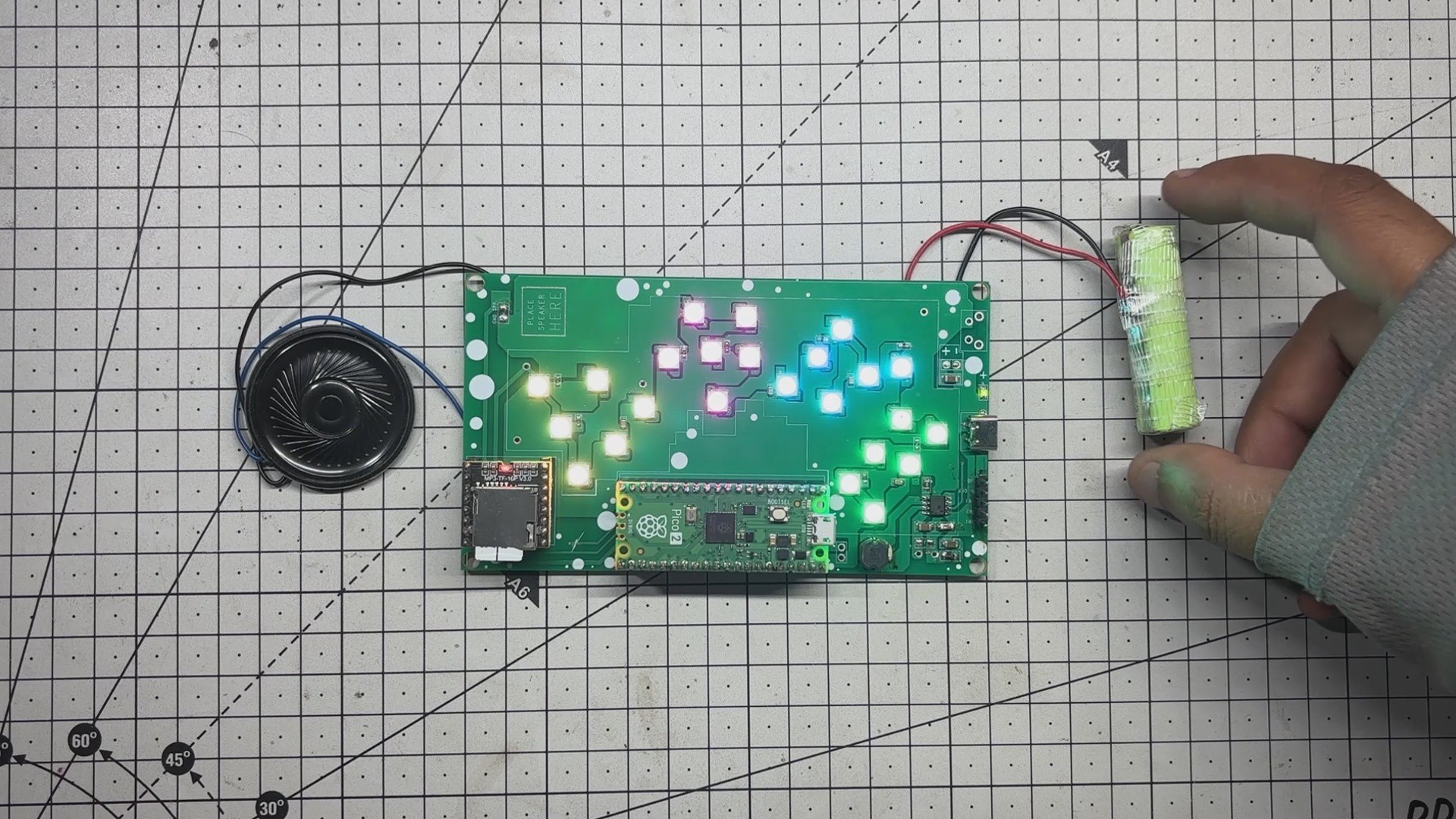
The original plan was to use a standard 18650 Li-ion cell but ended up using a 14500 lithium cell. It offers the same operating voltage of 3.7V but with a smaller form factor and approximately half the capacity — around 600mAh.
The positive and negative terminals of the 14500 cell were soldered directly to the board’s battery connector using a soldering iron, completing the power circuit.
-
5MAIN CODE
![]()
Here's the main code we used in this project and it's a simple one; let me explain.
#include <SoftwareSerial.h>
#include <DFRobotDFPlayerMini.h>
#include <Adafruit_NeoPixel.h>
SoftwareSerial mySerial(7, 8); // RX, TX
DFRobotDFPlayerMini myDFPlayer;
const int totalSongs = 4;
int currentSong = 1;
int currentVolume = 20;
// Button pins
const int nextPin = 12;
const int volUpPin = 13;
const int volDownPin = 14;
// LED setup
#define LED_PIN     0
#define LED_COUNT   24
Adafruit_NeoPixel strip(LED_COUNT, LED_PIN, NEO_GRB + NEO_KHZ800);
void setup() {
Serial.begin(9600);
mySerial.begin(9600);
pinMode(nextPin, INPUT_PULLUP);
pinMode(volUpPin, INPUT_PULLUP);
pinMode(volDownPin, INPUT_PULLUP);
strip.begin();
strip.show();
if (!myDFPlayer.begin(mySerial)) {
Serial.println("DFPlayer Mini not found");
while (true);
}
myDFPlayer.volume(currentVolume);
delay(1000);
myDFPlayer.play(currentSong);
updateLEDs();
}
void loop() {
if (myDFPlayer.available()) {
uint8_t type = myDFPlayer.readType();
if (type == DFPlayerPlayFinished) {
currentSong++;
if (currentSong > totalSongs) currentSong = 1;
myDFPlayer.play(currentSong);
}
}
// ⏳ Press-and-hold logic for next song
static unsigned long nextPressStart = 0;
if (digitalRead(nextPin) == LOW) {
if (nextPressStart == 0) nextPressStart = millis();
if (millis() - nextPressStart >= 1000) {
currentSong++;
if (currentSong > totalSongs) currentSong = 1;
myDFPlayer.play(currentSong);
nextPressStart = 0;
while (digitalRead(nextPin) == LOW); // Wait for release
}
} else {
nextPressStart = 0;
}
// Volume Up
if (digitalRead(volUpPin) == LOW) {
delay(200);
if (currentVolume < 30) currentVolume++;
myDFPlayer.volume(currentVolume);
while (digitalRead(volUpPin) == LOW);
}
// Volume Down
if (digitalRead(volDownPin) == LOW) {
delay(200);
if (currentVolume > 0) currentVolume--;
myDFPlayer.volume(currentVolume);
while (digitalRead(volDownPin) == LOW);
}
}
void updateLEDs() {
for (int i = 0; i < LED_COUNT; i++) {
if (i < 6) {
strip.setPixelColor(i, strip.Color(255, 255, 0)); // Yellow
} else if (i < 12) {
strip.setPixelColor(i, strip.Color(255, 0, 128)); // Pink-purple mix
} else if (i < 18) {
strip.setPixelColor(i, strip.Color(0, 255, 255)); // Cyan-blue
} else {
strip.setPixelColor(i, strip.Color(0, 255, 0)); // Light green
}
}
strip.show();
}
In our Setup we have used three key libraries:
•SoftwareSerial for serial communication
•DFRobotDFPlayerMini to control the DFPlayer audio module
• Adafruit Neopixel to drive the RGB LEDs
The setup includes four buttons: one for skipping tracks (press-and-hold), one for volume up, one for volume down, and one for power. When a button is pressed, the device responds accordingly changing the song, adjusting the volume, or triggering LED behavior.
The RGB LEDs glow continuously, split into four color zones: yellow, pink-purple, cyan-blue, and light green, each mapped to a section of the front PCB. The code also handles automatic track progression when a song finishes.
-
6FINAL ASSEMBLY
![]()
![]()
![]()
![]()
![]()
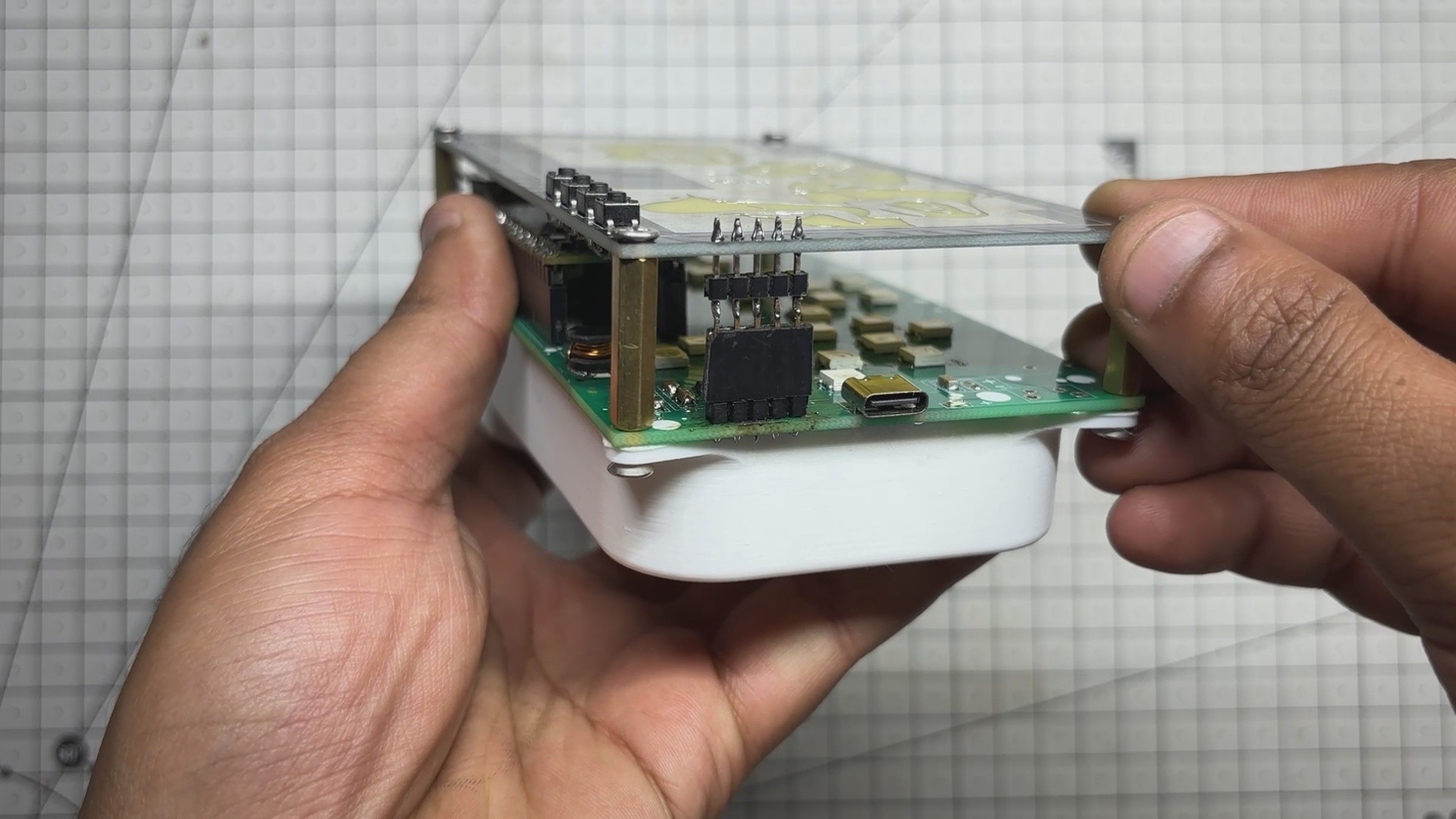
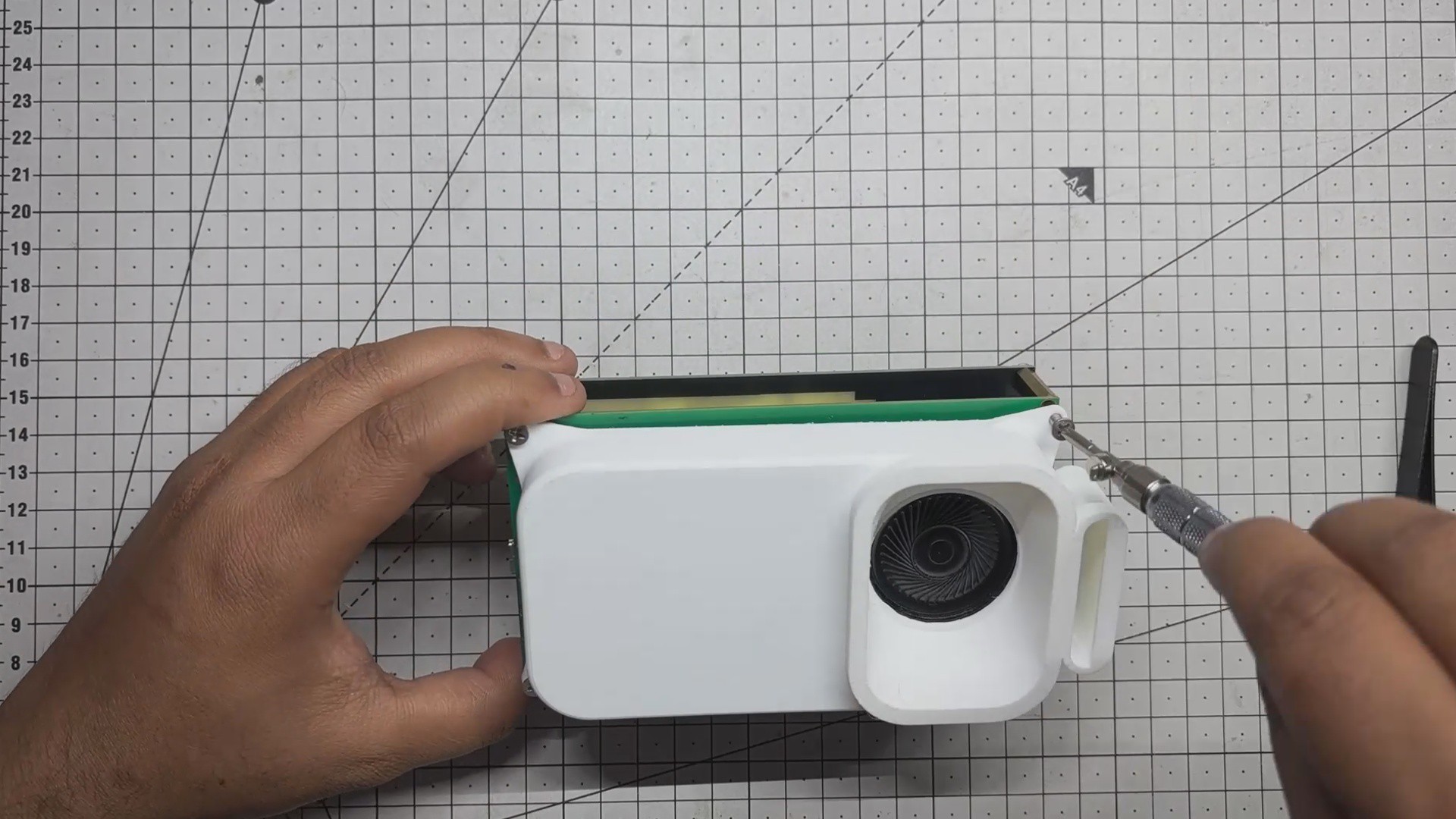
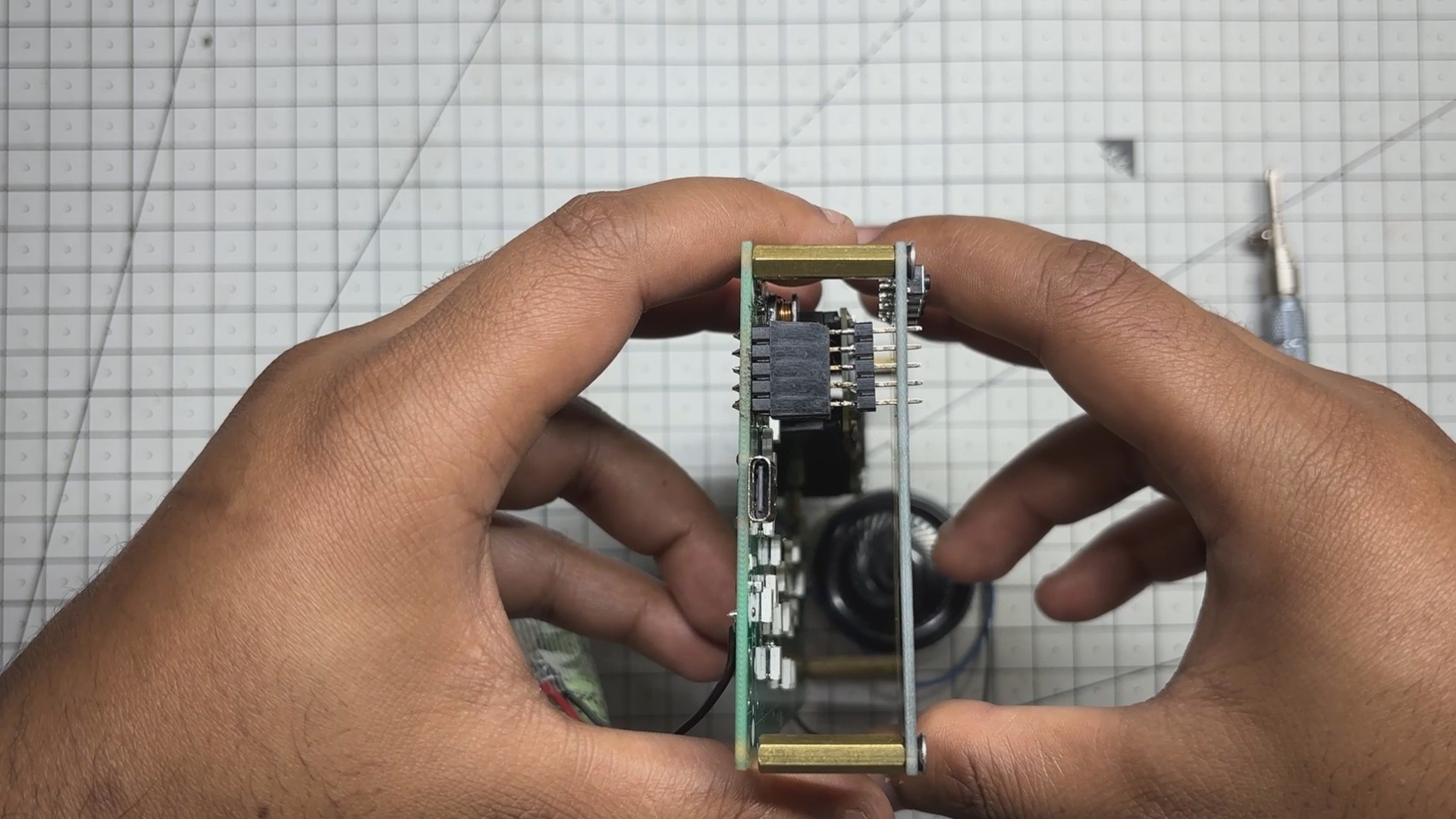
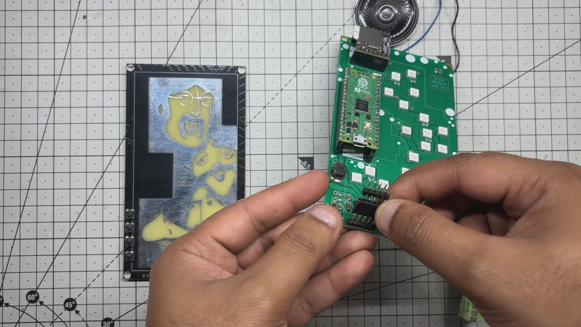
- To connect the main PCB with the front PCB, we use a custom-built CON5 header, a makeshift connector made by soldering a male header pin directly to a female header pin. This hybrid setup plugs into the male CON5 connector on the main board, creating a reliable link between the two PCBs.
- Next, we install four M2.5 PCB standoffs into the mounting holes of the front PCB. With the header connector and standoffs aligned, we carefully sandwich the front PCB onto the main board, locking the two layers together both electrically and mechanically.
- We then move to the enclosure. A 3D-printed shell houses the speaker and lithium cell, which are placed securely in their designated slots. The entire enclosure assembly is positioned behind the main PCB, and four M2. 5 screws are used to fasten everything together—completing the build.
- At this point, the device is fully assembled.
-
7RESULT
![]()
![]()
![]()
![]()
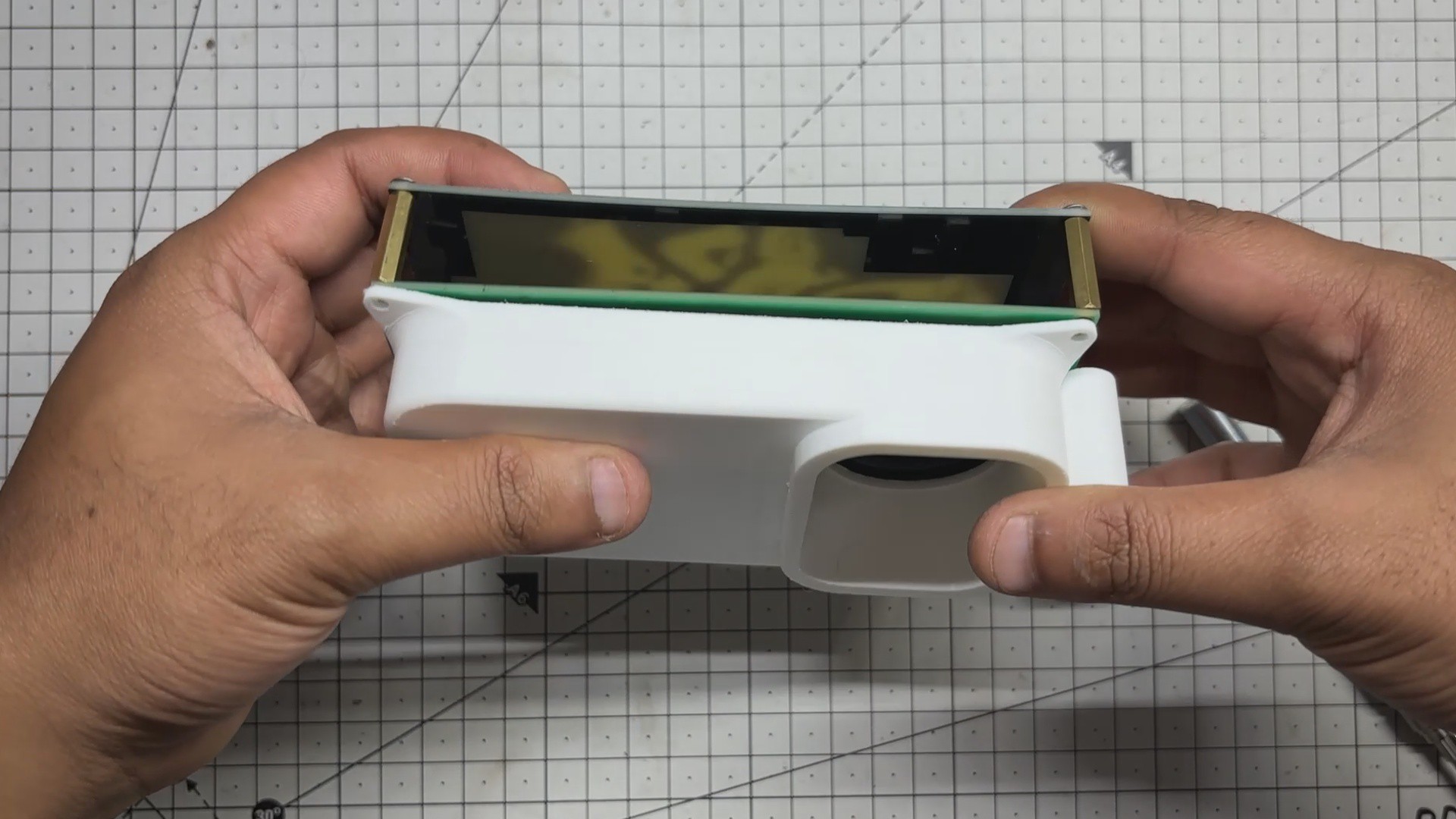
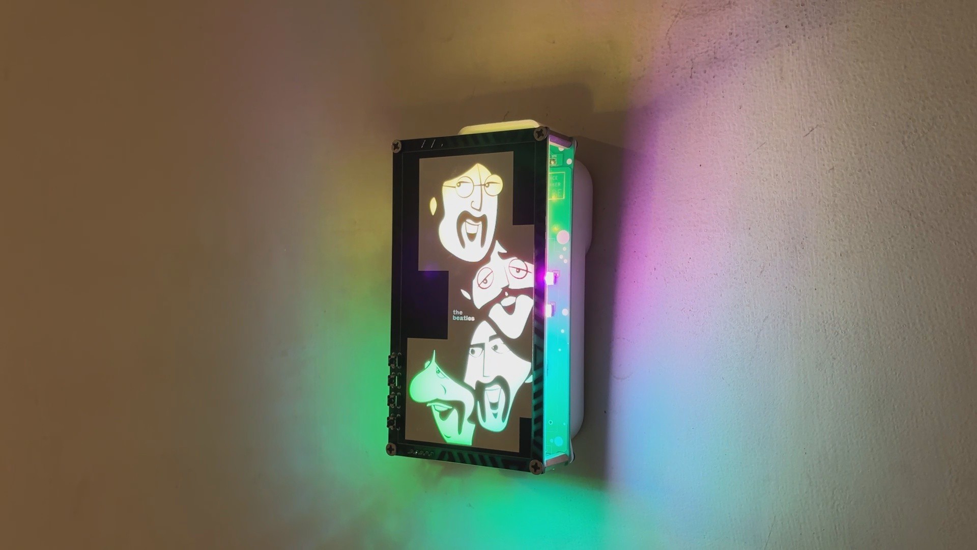
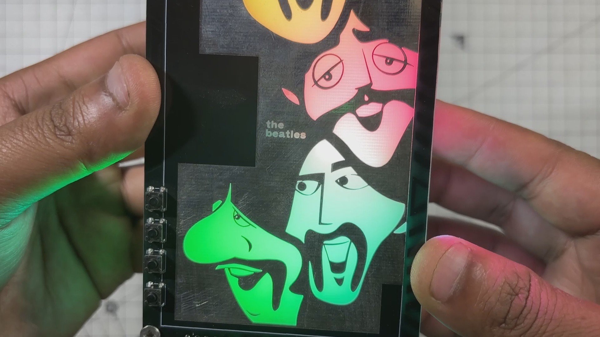
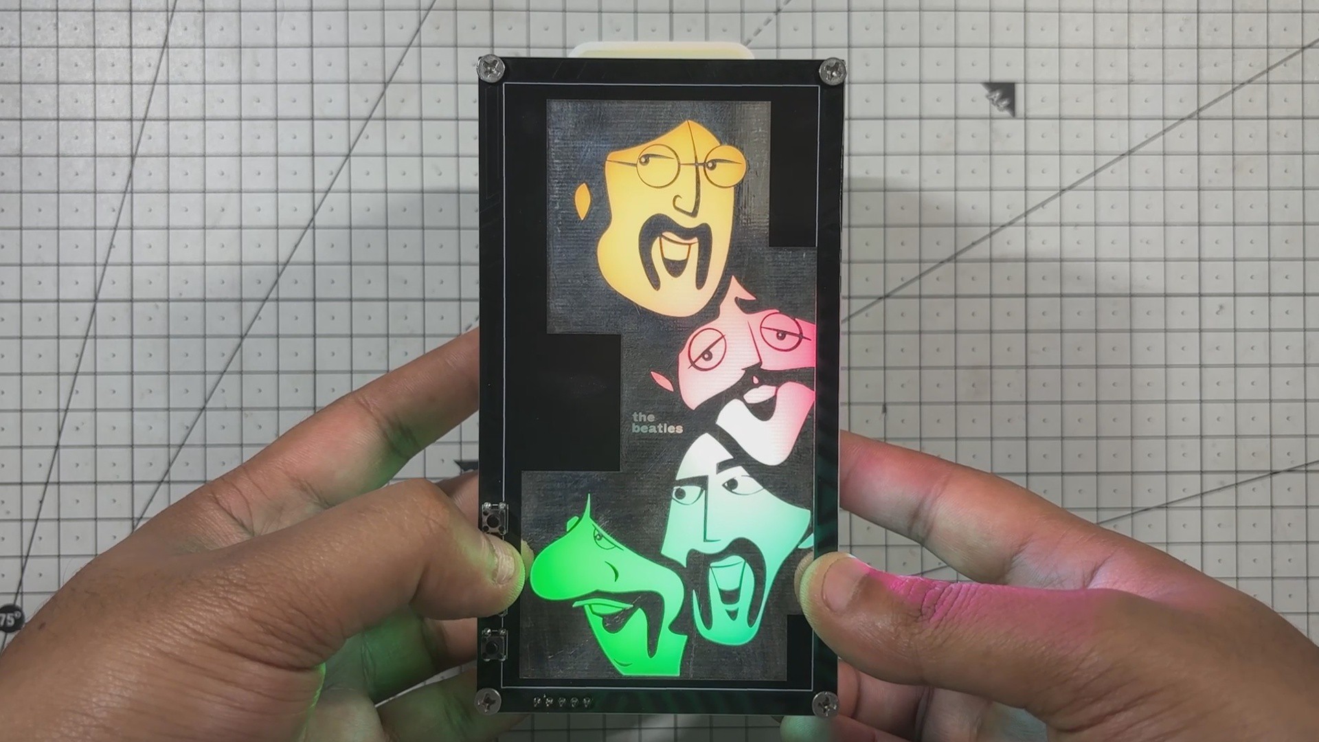
Here’s the end result of this simple yet fun build-a Beatles-themed art-light music player that’s hard to categorize. It plays a selection of Beatles songs stored on an onboard SD card and features a custom front panel with cartoon-style illustrations of the four original Beatles members.
The panel glows in four distinct colors, each mapped to a zone of RGB LEDs beneath the artwork, giving the device a vibrant, aesthetic feel. It’s designed to rest on my desk, right beside my monitor, but I also added a hook so it can hang on a wall using a nail.
It’s not just a music player. Not just a lamp.
It’s a fusion of sound, light, and illustration a personal tribute built from electronics combined with ART.
Thanks for reaching this far, and I will be back with a new project soon.
The Beetles PCB ART
It’s a PCB art board. It’s a music player. It’s something else entirely. Hard to define


Discussions
Become a Hackaday.io Member
Create an account to leave a comment. Already have an account? Log In.