 Max.K
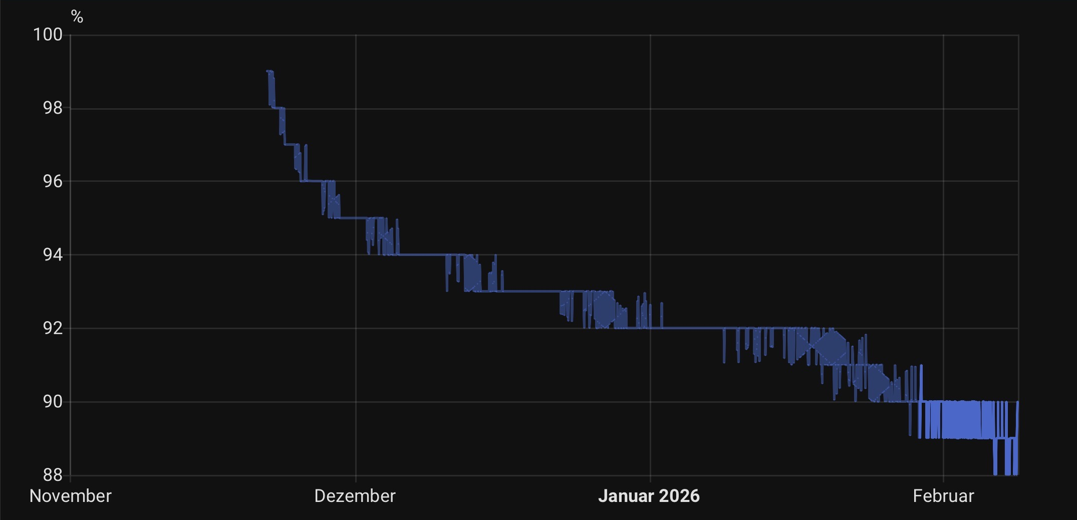
Max.KOver the past few months I have been using the Zicada boards with HomeAssistant. So far, the results looks promising but are a little ambiguous. On two sensors, the battery life seems great with 88% charge left after rougly 3 months. These batteries should last for another year before needing to be recharged. But a third sensor, which has been running for the same duration, is now at 60% already. I am pretty sure this is not a hardware issue and the sensor might be performing better after a reset.
There are a few little other issues or bugs left, where I am not sure whether this is due to my design or just Zigbee's overall complexity. For example, devices might take a few tries to complete their interview. Or some attributes are not reported at all, requiring a reset of the device. But usually, once everything work with a particular sensor, it stays that way.
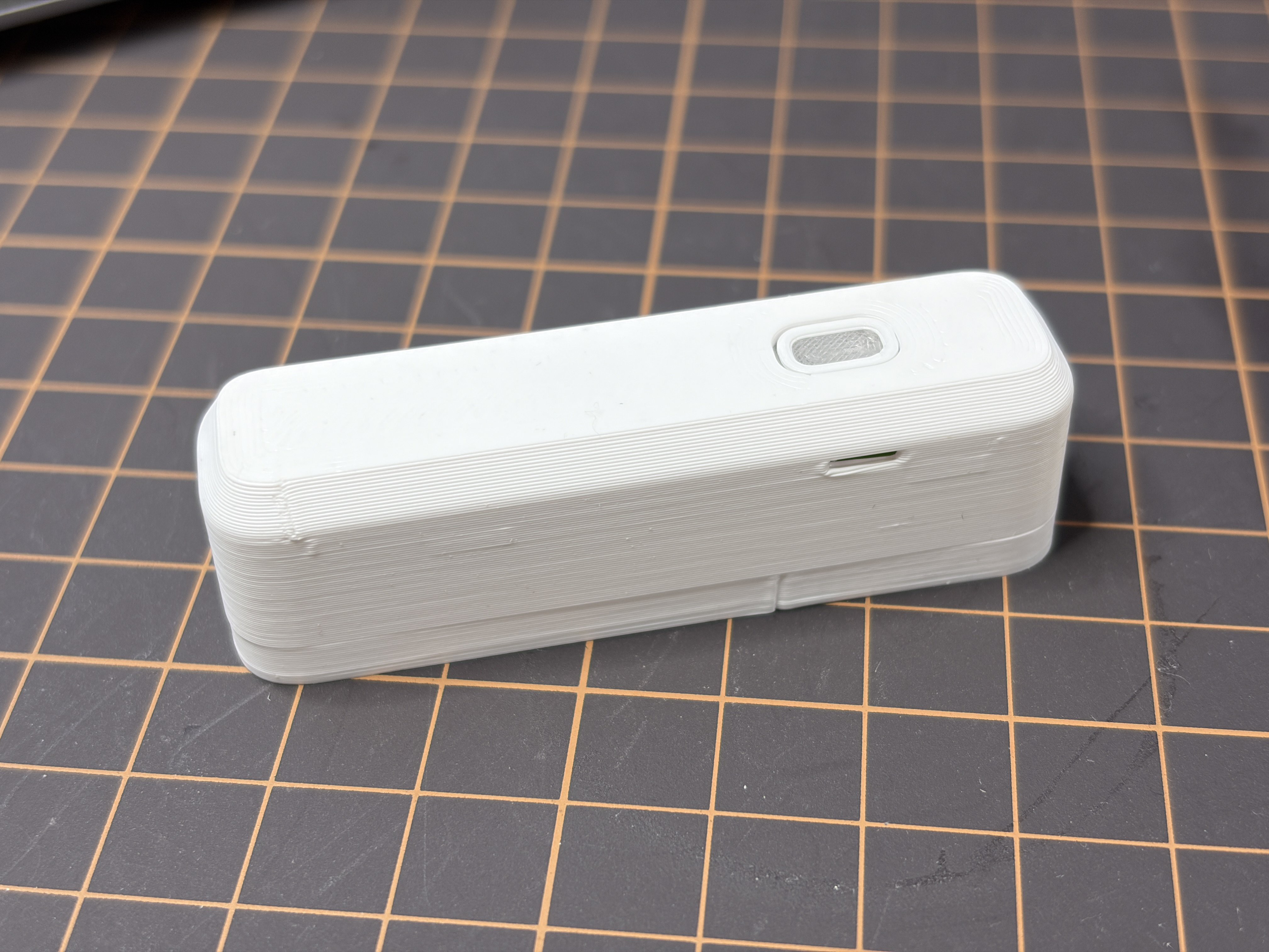
I have gotten some great feedback from the YouTube video. A few people noticed the lack of airflow to the temperature and humidity sensor. This is a valid point, since the gap between the case and button only lets very little air through, making the sensor react slower than it needs to. So I designed an updated version of the case with holes for improved airflow.
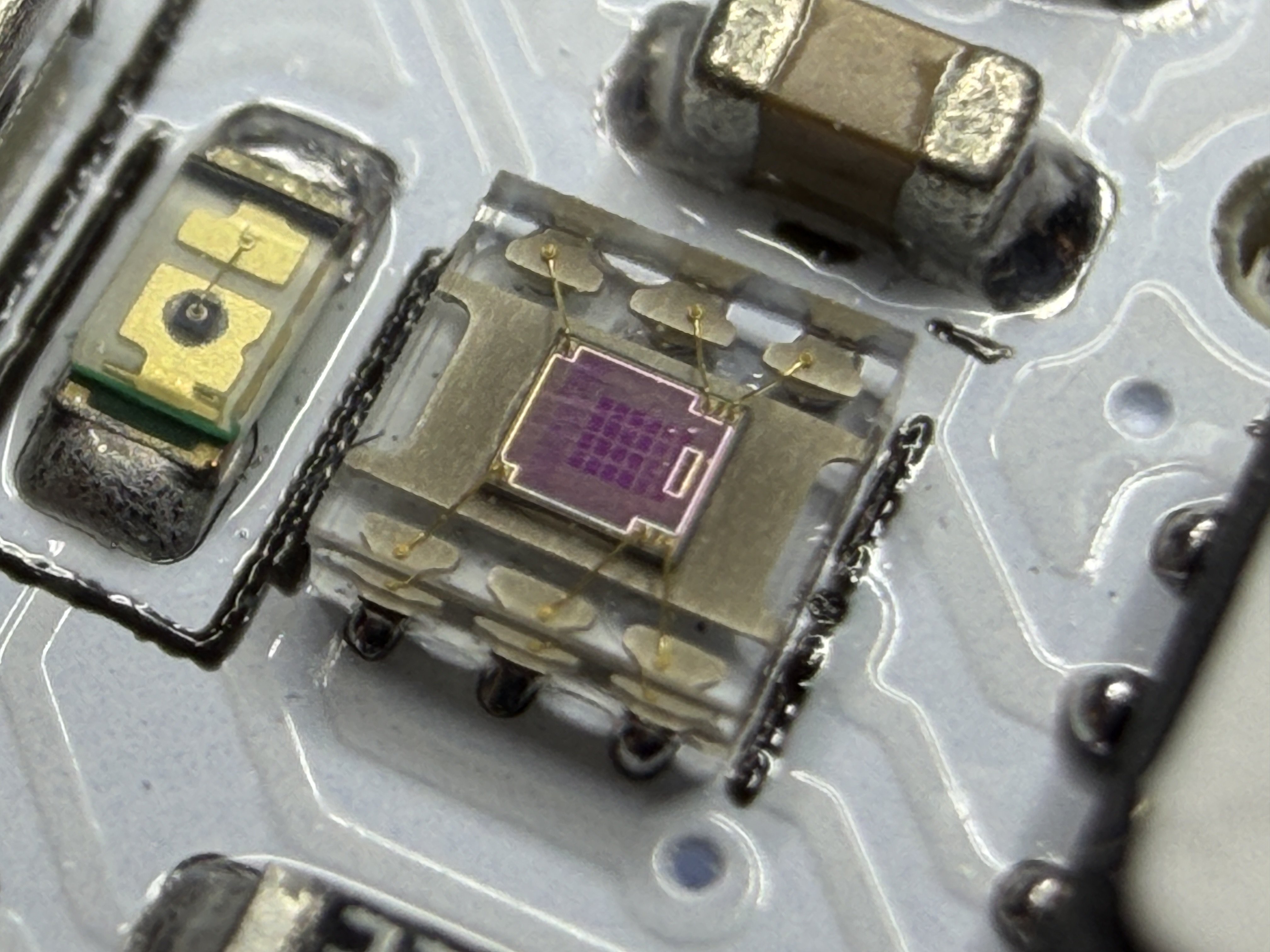
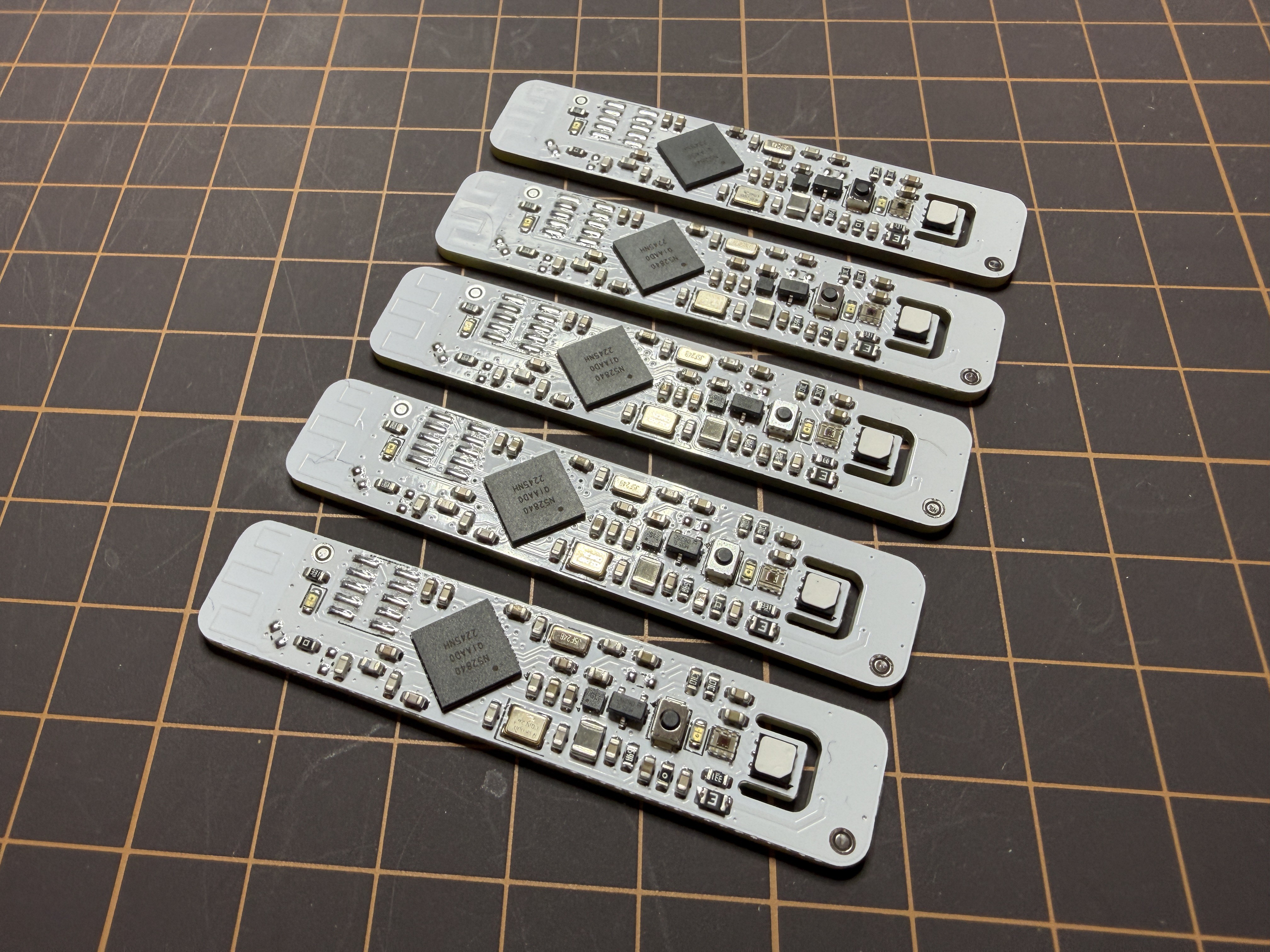
Since I wanted to order a few more PCB for myself, I wanted to include another feature, that was mentioned a few times: A light sensor. On the PCB, there was just enough space near the button for a TI OPT3001 brightness sensor. This little sensor uses the existing i2c bus on the board for communication, so no more pins or routing were needed. This sensor looks really gorgeous with its translucent case, measuring only 2x2mm.
The firmware needed some updates to read the sensor and to integrate the Zigbee illuminance cluster. Luckily, Zephyr comes with a driver for the OPT3001, so the sensor was up and running in no time. One problem with the driver was, that it forced the sensor in a continous mode, where it adds around 4µA to the power draw (the battery voltage is stepped up, so the sensor actually only draws 2uA @ 2.2V). Instead of modifying the driver, I am just overwriting the mode setting by writing to the register directly via i2c. The sensor now only wakes up when is needed. This got the power draw of the entire board down to 7.2µA, only 1µA more than before the addition of the light sensor.
The reset button already has a translucent center since it used for the status LED. I increased the size of the button to let more light in. The button is directly above the light sensor so this should be enough to get a relative estimate of a room's brightness. Of course, this will not be a very precise measurement, since the 3D-printed button still absorps some of the light.
The updated code, PCB files and 3D-printed files are available on GitHub in a separate branch, until I have done some more testing: https://github.com/CoretechR/Zicada/tree/boardrev3
Discussions
Become a Hackaday.io Member
Create an account to leave a comment. Already have an account? Log In.