Close
0%
0%

ESP32 NTP Clock

A Clock that sets itself over WiFi

Similar projects worth following
First there was my GPS clock. Then, for situations where GPS reception wasn't easy or possible, I made a Raspberry Pi Zero clock. But the Pi is a bit overkill. The middle ground is this project: A clock display driven by an ESP32 that fetches time via NTP over WiFi.

Going back to the first iterations of the GPS clock, the display is managed by a MAX6951. The SPI pins are connected up to the default SPI interface pins of an ESP32-C3-MINI-1 (pin 0 CLK, pin 3 DIN, pin 10 !CS). The boot selector pin (pin 9) goes to a solder jumper. To place the ESP32 in the sketch upload mode, you short that jumper out while applying power (I find a piece of solder wick braid best for this. Just hold it on the pads while plugging it in). The barrel connector for power has been replaced with a USB-C socket. This allows the same connector to be used for firmware updates as well as normal power. The only other addition is a single button that goes to pin 4. This button puts the clock in the setup mode.

On the firmware side, I needed to find a high-precision NTP client implementation. The ones that sort of come with Arduino are only good to the second and I wanted to display tenths and for them to be reasonably accurate. To do that, I turned to the ESPNtpClient library. But that library has a crash bug in it, so I found this fork that works properly. You'll want to install that version in your IDE if you want to build the firmware yourself.

When the clock boots up, it uses the preferences API to load the WiFi, NTP and feature configuration. The clock will show a brief LED test and then show "no ntP" until the clock is synchronized with the NTP pool.

At any time, you can push the setup button. The display will show "SEtuP" and the board will go into WiFi AP mode with the SSID "ESPClock". Once connected, open a web browser and you should find a captive portal that will redirect you to a setup UI where you can put in the correct WiFi SSID and password (WPA2 and WPA3 personal are supported), override the default NTP server if you wish, change the display brightness, set 12 or 24 hour mode, enable or disable the tenth of a second digit, set the mode for the colons (off, on or blink) and select your time zone (or enter your own time zone string). Once you submit that page, the preferences will be updated and the clock rebooted.
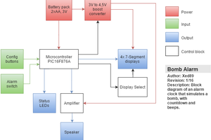
esp_clock_1_0.brd

brd - 122.50 kB - 11/20/2025 at 22:10

Download

esp_clock_1_0.sch

sch - 276.71 kB - 11/20/2025 at 22:10

Download

esp_clock_1_0.pdf

Adobe Portable Document Format - 56.31 kB - 11/20/2025 at 22:10

Preview

  • First build report

    Nick Sayer2 hours ago 0 comments

    The boards from OSHPark came back and they work just fine. Shorting the boot pads while applying power puts it into the firmware loading mode as expected and the firmware worked the same as it did on the prototype.

    Moreover, the board fits just fine in the 3D printed case. That was simply a modified version of the GPS clock case, with some of the lettering changed, one of the button holes removed, the antenna hole removed and the power hole elongated to accommodate a USB-C jack.

    I am going to order a v1.1 board. It will move the ESP closer to the USB jack just to cut down on the trace lengths and replace the TVS diode with a USB protection diode array that protects the data lines as well as the VUSB. When that comes back and is tested I'll probably get some assembled and add them to the store.

  • Config web UI & accuracy checks

    Nick Sayer11/20/2025 at 21:39 0 comments

    I was able to figure out how to do the configuration UI. Pressing the "setup" button will display "SEtuP" on the display and create a WiFi network called "ESPClock". Connect to that and then surf to the web page at 192.168.4.1 and you'll get a form to put in the SSID, password, hostname NTP server and set things like 12/24 hour mode, enabling or disabling the 10th of a second digit and setting the mode for the colons.

    I was also able to perform a rudimentary accuracy check on the clock. I took some slow-motion videos of the ESP clock prototype next to one of my GPS clocks. The iPhone slo-mo video seems to me to be running at about 120 FPS or so, so any given frame is maybe 8 ms or so away from its neighbor. Immediately after startup, the two clocks were changing the tenth-of-a-second digit about 6 frames apart, which is not great, but after sitting for an hour the two clocks were changing in perfect unison. Even at the start they were within 50 ms of each other, so that's still not too much to complain about. I'm certainly confident that it'll be just as accurate or more than the Pi clock I used to have.

  • Prototype results

    Nick Sayer11/20/2025 at 18:02 0 comments

    The prototype is up and running. It consists of the Pi clock display board with the Pi removed and a SparkFun Pro Micro ESP32-C3 hooked up to it with 5 jumper wires. The wires cary the 3 lines of the SPI interface (MISO is not used), ground and +5. This setup has allowed me to develop the firmware and validate the design (at least as much as possible).

    At the moment, the bit still missing is the setup system, which puts the WiFi into AP mode and puts up a web server. That's still TBD. But everything else is working, and that's good enough to move on to dedicated hardware.

    The first board has been ordered from OSHPark as well as raw C3-Micro modules from DigiKey and a paste stencil for the modules. Fingers crossed for the first build!

View all 3 project logs

Enjoy this project?

Share

Discussions

Does this project spark your interest?

Become a member to follow this project and never miss any updates