 Omer Inbar
The Z-axis actuation is done by moving a base plate along the robot’s tower. The tower’s stiffness under load is the main weakness of the configuration I chose. It’s actually quite difficult to make a 300mm tall, 3d printed linear actuator that is both stiff and smooth without going for expensive profiles and linear rails, which I wanted to avoid.
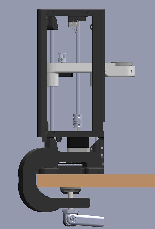
Like others before me, I went with linear ball bearings on steel rods that serve both as the guides and as the main structural element, and they’re very cheap.
My first build used 6 mm rods with 19 mm long bushings (LM6UU), and it was nowhere near strong enough, both in terms of bending and in the amount of play of the plate on the rods.
For the next iteration I upgraded to 8 mm rods with 45 mm long bushings (LM8LUU) and added an external plastic frame, which turned out much better.
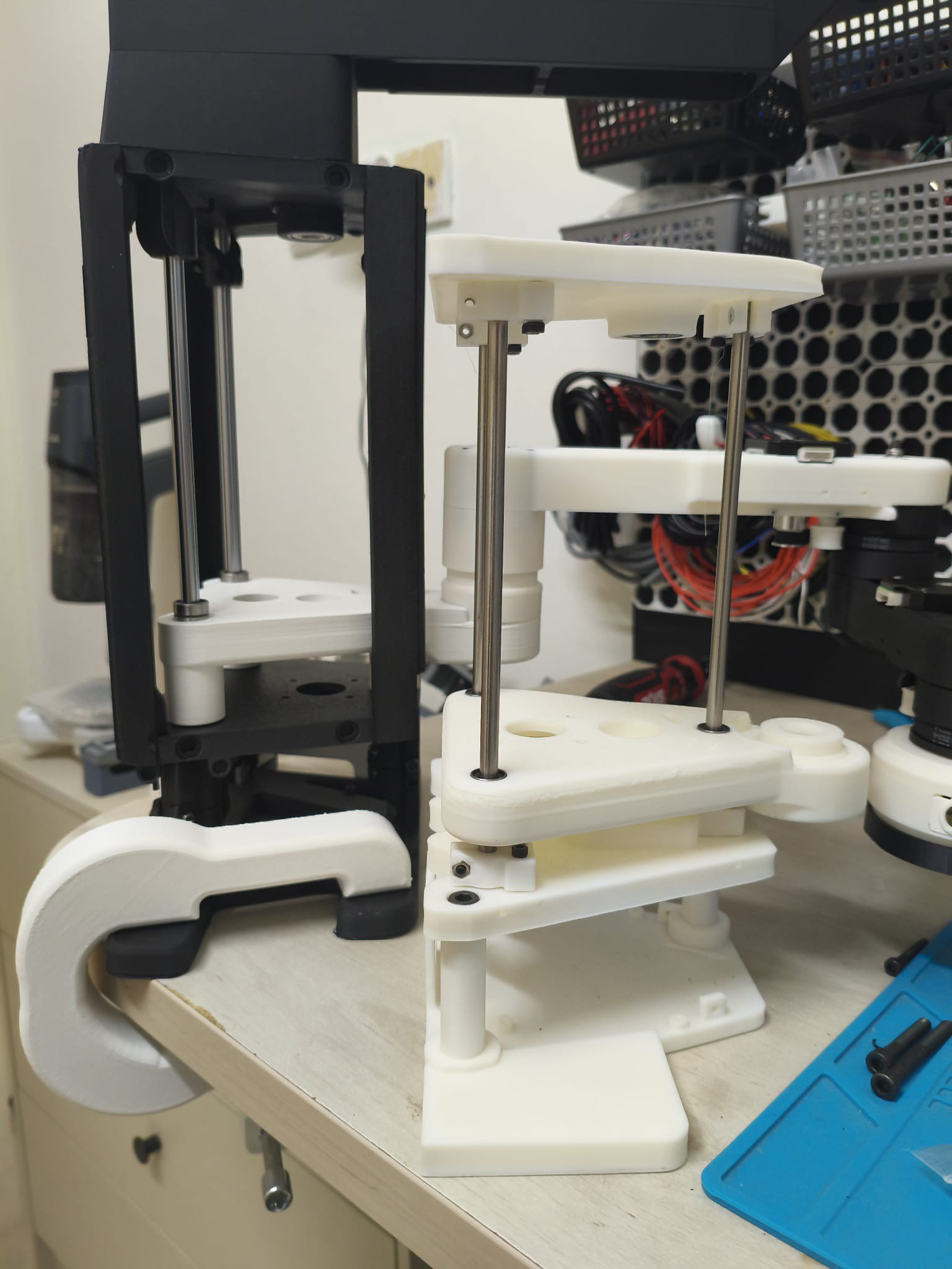
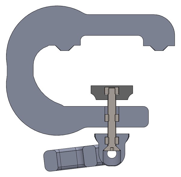
The robot is mounted by clamping or bolting the flaps on the sides of its base, and those also bend a bit when force is applied to the top. In the second iteration I thickened the flaps and designed printed clamps that press nicely on all four corners of the base. To get that to work, the clamps have to make contact with the front corners first, because as they are tightened the clamp bends and that deflection increases the force on the back corners.
there are still several regions in the tower that get some flex so i am still working on stiffing it up, looking into embedding steel brackets in the prints. if any one has some advice it would be most appreciated.
Discussions
Become a Hackaday.io Member
Create an account to leave a comment. Already have an account? Log In.