 patrick.souty
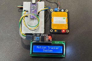
The tachometer is based on a tracking line sensor KY-033. A black tape is sticked on 180° of the lathe rotating axis. The sensor detects the alternance between the black surface and the bright aluminium surface once per rotation. An Arduino Nano board is used to detect sensor output changes and manage a 4 digits, 7 segments LED display. All these parts are coming form an Arduino kit which was offered to me.
The software uses interrupts from the sensor input. At each interrupt, the current time T1 in µseconds is saved and the rotation speed in rpm is computed as 60 / (T1 - previous T1) x 10E6.
In addition, to avoid spurious interrupts due to noise, the interrupt is disabled during 40% of the sensor signal period thanks to the timer 2 which is armed on interrupt receipt.
Timer 1 has been used to simulate sensor output during test phase.
Display management requires 12 AVR328 outputs. I have used D2 to D10 and A3 to A5 as analog inputs can be used also as standard digital ports.
The sensor output is connected to A2 input which is used as a digital input.
Power supply is fed by a standard power supply bloc through a barrel jack connector.
The sensor is connected through an stereo audio jack connector.
The overall electronic and connectors are housed in a box 3D printed. Other parts 3D printed are used to attach the sensor and the tachometer box to the lathe.
The tachometer unit is easily detachable from the lathe and can be used on my other CNC machine to monitor spindle speed. I will only need to attach a sensor in front of the spindle.
In order to make wiring simple, I have made a dedicated PCB for Arduino and display + resistors connections. The PCB has been designed with Kycad and and drilled with a CNC 3040 machine using a single layer PCB.
This was my first use of this machine. Previously, I was using an CNC 3018 which was less precise. However I had to make two tries before obtaining good results, though the new machine was supposed to be much better. I understand at the end that the issue was that I was using raw PCBs that were at least 40 years old and their copper thickness was 70 µm and not the usual 35µm. As the machine was more precise, it was actually drilling at 50 or 60µm deep and that was not enough.
You can find more details in the attached files (coming soon).
 Lithium ION
 the.wretch
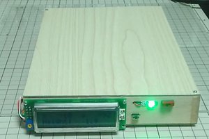
 HomeMadeGarbage
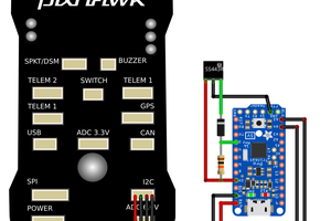
 Peter McCloud