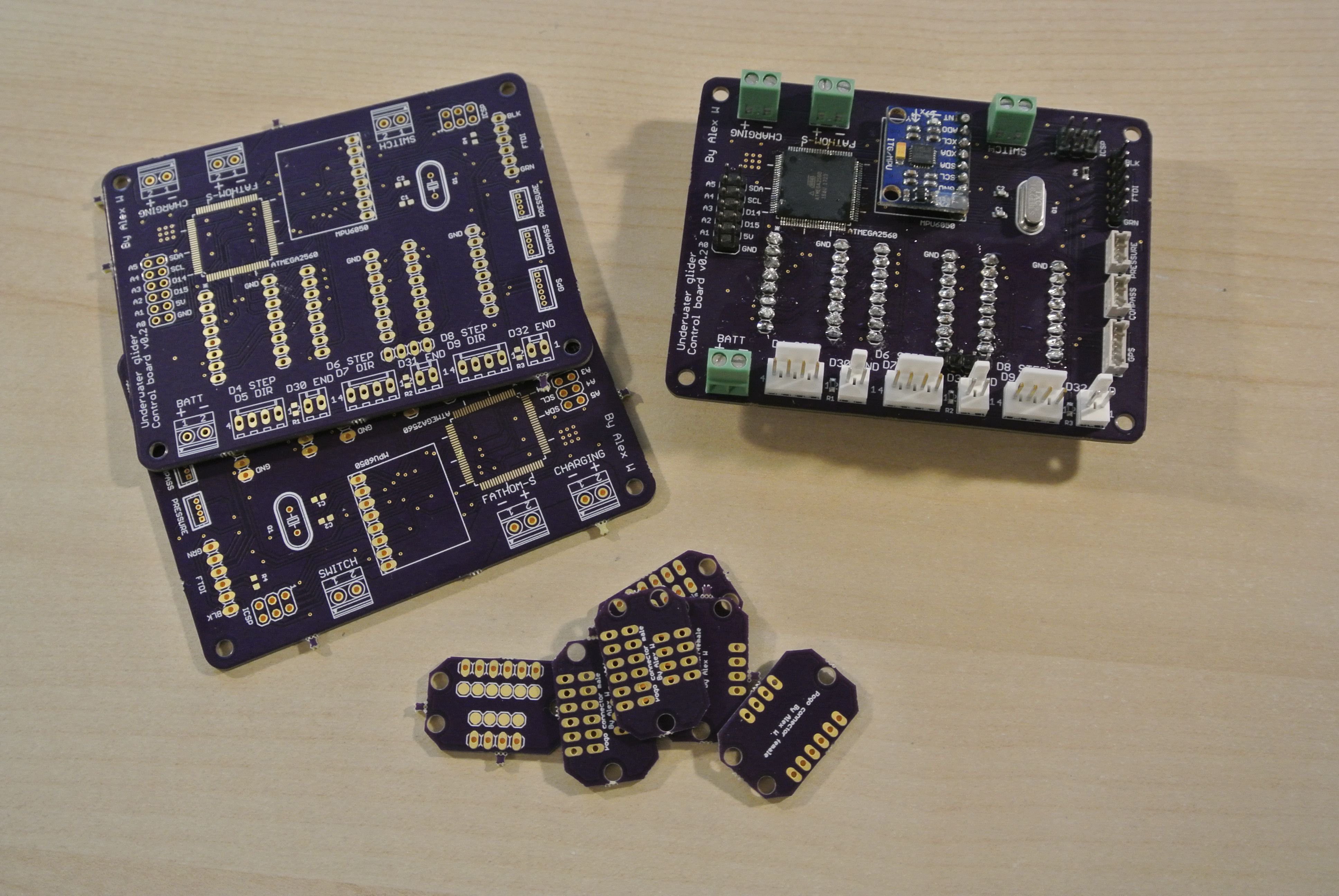
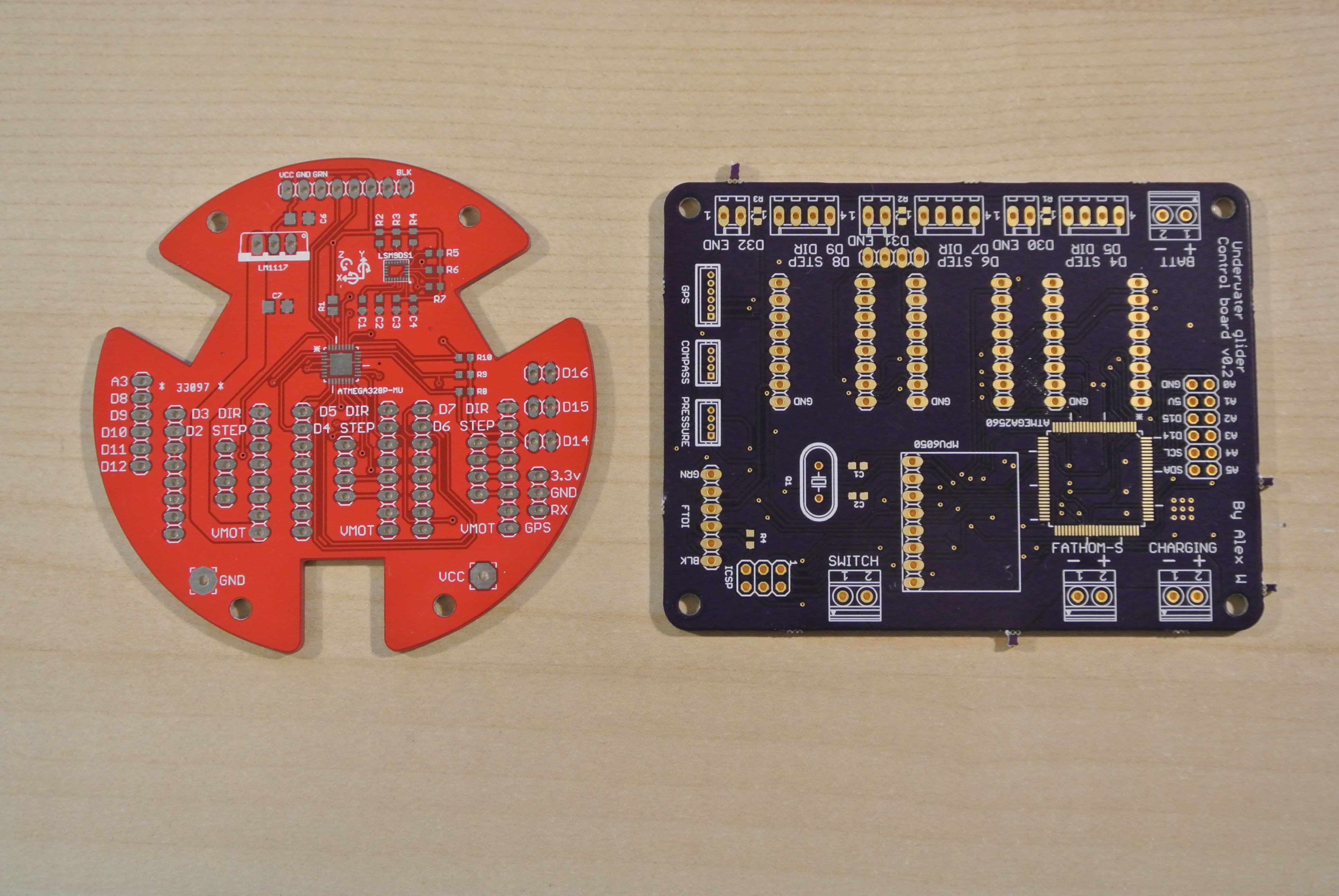
The PCBs have arrived from OSHpark (I was impressed at how quick they were, 9 days to the UK with the super swift service and super saver delivery) and are the very high quality you would expect with OSH park.

Population of the board was relatively straightforward; there are a couple of SMD components and the majority of the other components are through hole headers (this version of the control board is a glorified breakout board). The new control board is only a little bit larger than the previous version, but will be mounted horizontally as opposed to vertically.

I have also designed a mount to attach the Fathom-S board to the control board.

The Fathom-S board mount can be exported from the Onshape CAD model (right click on a part and select "Export" to download the STL of a part)
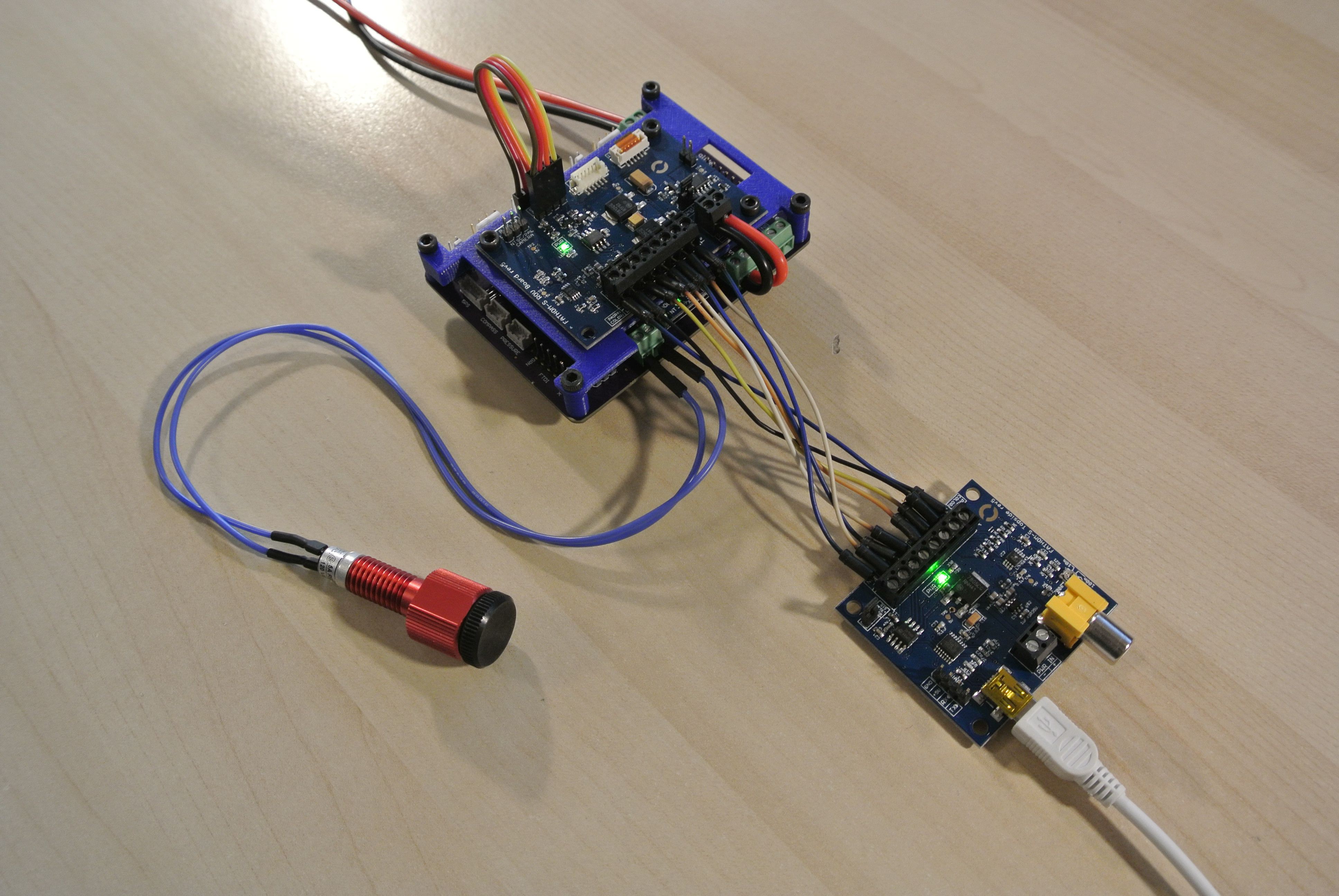
There is a error whilst uploading to the control board via the FTDI header ("avrdude: stk500v2_ReceiveMessage(): timeout"), but programming via the Fathom-S boards is fully functioning. (the 8 wires connecting the two Fathom-S boards can be replaced with up to 600+ metres of Fathom cabling)

When programming over the Fathom-S boards, the glider's boards will only power on if the USB is attached to the topside board. However, if not programming, the boards can also run standalone off of batter power. I plan on using a Bulgin Standard Series buccaneer connector so that you can disconnect the Fathom cabling, making this feature is very useful.

After attaching the Fathom-S board, I made a couple of changes to the control board (moving a couple of headers a millimeter or two and changing the silkscreens a little to make them more useful/clear) The latest board version is v0.2.1 and can be found in the development folder on Dropbox (Glider_PCBs/Control_board/v0.2.1). As with version v0.2, there is an error when uploading the .brd file to OSH Park (related to the SMD capacitors; remove them and it works, add them from the default rcl library and it breaks, I have no idea what is going on), so a zip folder containing all the gerber files is also found within the Dropbox folder.
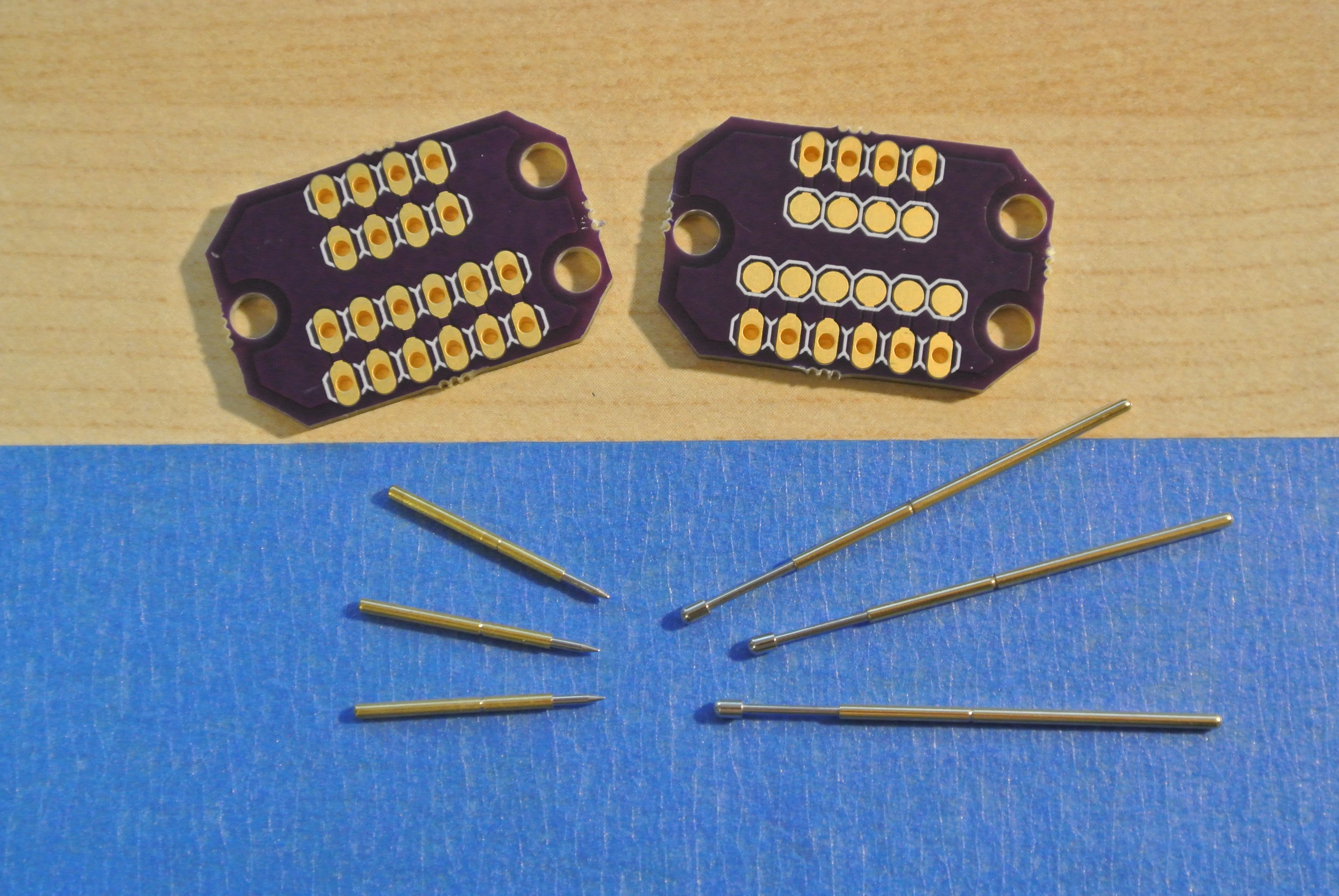
I also ordered a couple of PCBs to help with cable management. On the second generation glider, there was a set of cables running from the buoyancy engine (stepper motor/endstop wiring) that had to be plugged into the control board, but this would be hard to plug in and slack would occur in the wiring, interfering with the movement of the mass assembly. To fix this, I produced a pair of PCBs, one for the front end of the glider and one for the back. When the back end is slid into the tubing, pogo pins would touch against the pads on the front end PCB. One potential issue with this design is that the two PCBs will have to be within a couple of millimeters of their required positions, as the pogo pins do not compress much (2mm). Moreover, the blue robotics tubing can vary by ±3mm, so the user must be able to set the PCB positions themselves.

The two PCBs are both within the Dropbox folder: Glider_PCBs/Buoyancy_engine_connector_female and Glider_PCBs/Buoyancy_engine_connector_male.
 alexw
alexw
Discussions
Become a Hackaday.io Member
Create an account to leave a comment. Already have an account? Log In.
Great update! We're excited to see you got the boards quickly.
Are you sure? yes | no