Richard P
ESPhomeMonitor
Hardware for monitoring equipment using HomeAssistant and Raspberry Pi Pico W-based ESPHome installation.
The boards described here are intended to be stacked, with the main Pico W board on top.
A 3D printable case is provided, with custom escutcheons for each input or output board type.
Boards- Main: Pico W, 3 x peak reading analogue inputs (400mV - 48V), filtered PWM output.
- Analog Input: 8 x analog inputs (3.5V - 48V) 3.81mm pluggable terminals or IDC connector.
- Analog Input (RVR): A specialised analog input board for RVR TEX150 transmitters and TXRL/RXRL STL.
- Digital Input: eight channels, opto-isolated or non-isolated. 3.81mm pluggable terminals or IDC connector.
- Digital Output: eight channels, 4 x opto-isolated + 4 x relays, or non-isolated. 3.81mm pluggable terminals or IDC connector.
- Expander Board: Second stack and additional 3.3V regulator.
The boards are designed in KiCAD. Gerbers and KiCAD source files are provided.
CaseA modular, 3D printable case is provided.
- Base with strain relief.
- Mid section for additional input and output boards
- Top section for main (Pico) board.
Each board type has a customised escutcheon panel that slots into the case, designed to be laser-cut from 2mm acrylic.
The case has a top panel with ventilation and mounting points for a SHT-40 I2C temperature and humidity sensor.
The case is joined together with 12mm tapped spacers and 15mm for the main Pico board.
Case files are in STL (body) or SVG (cover and escutcheons) format.
Documentation and configuration
- Technical overview (HomeAssistant Monitoring and Control.pdf)
- KiCAD design files and an example ESPHome configuration file for each board.
- HomeAssistant dashboard configuration is left to the constructor as needs will differ.
 J. Ian Lindsay
 Christoph
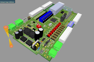
 daovanhoa12