-
1Step 1
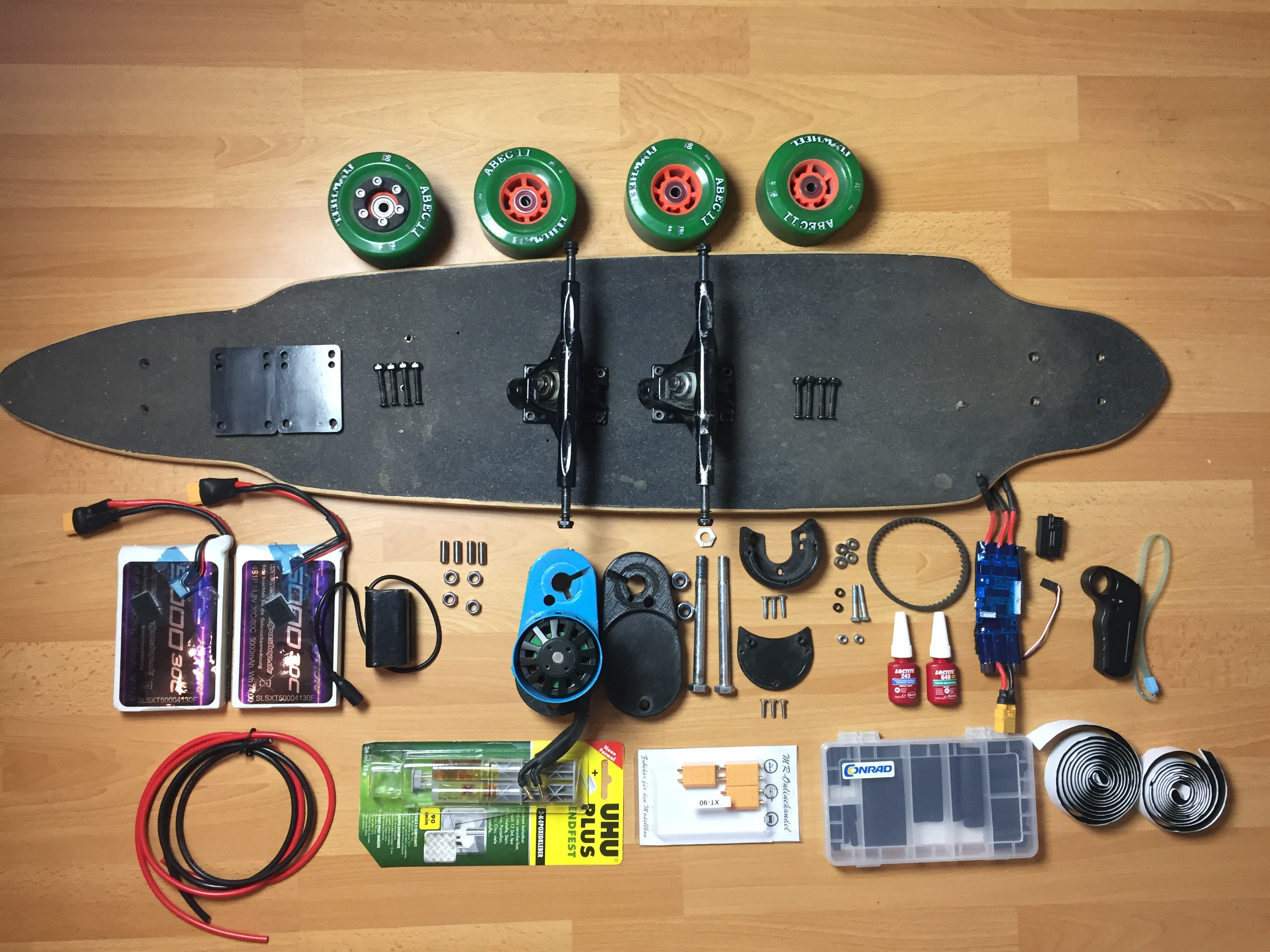
Step 1: What You'll Need
![]()
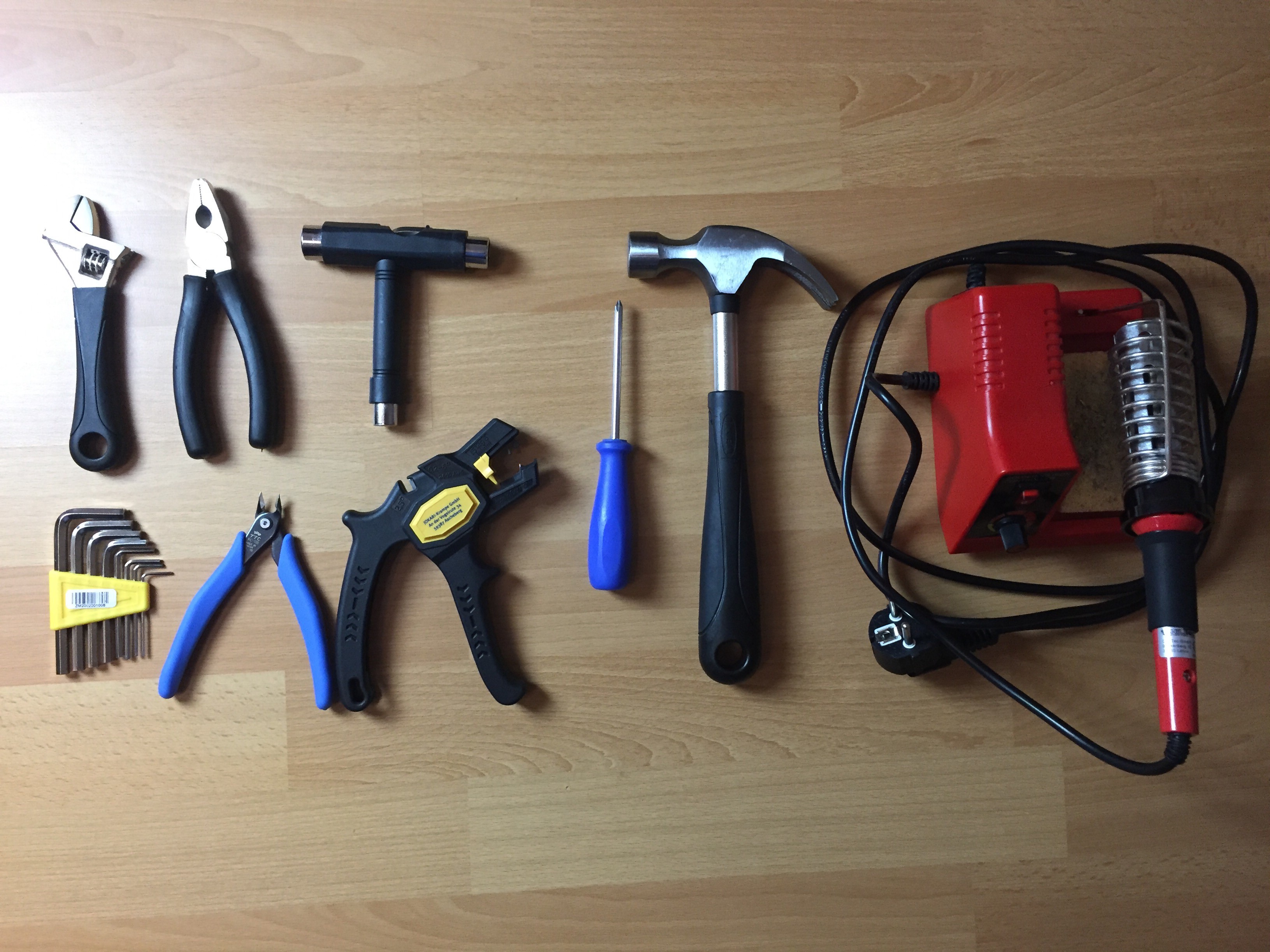
Tools:
- Variable Wrench
- Pliers
- Hex Wrenches
- Wire Cutter
- Wire Stripper/ Knife
- Skateboard T-tool
- Phillips Screwdriver
- Hammer/ Rubber Mallet
- Soldering Iron
-
2Step 2
Step 2: Wheels and Trucks
![]()
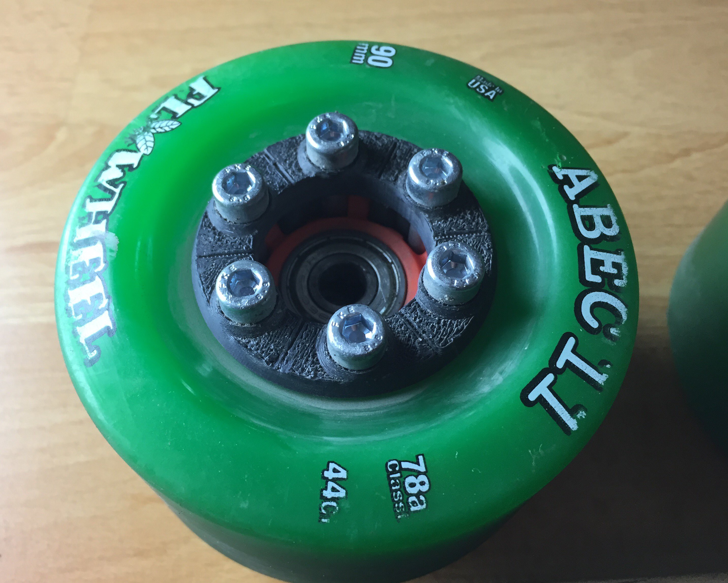
In this build, I used 90 mm ABEC Flywheels with these gears from Thingiverse. (Designer: brentyi) The design I chose was the HTD5 9 mm 40 Teeth gear. They require 6 x M5 x 73 mm Socket Screws and 6 X M5 Nylock Nuts. Once you have chosen your gear, your timing belt and pulley also has to be HTD5, 9mm wide.
Next, mount your trucks along with riser pads in order to increase clearance between the board and ground.
-
3Step 3
Step 3: Motor Mount
![]()
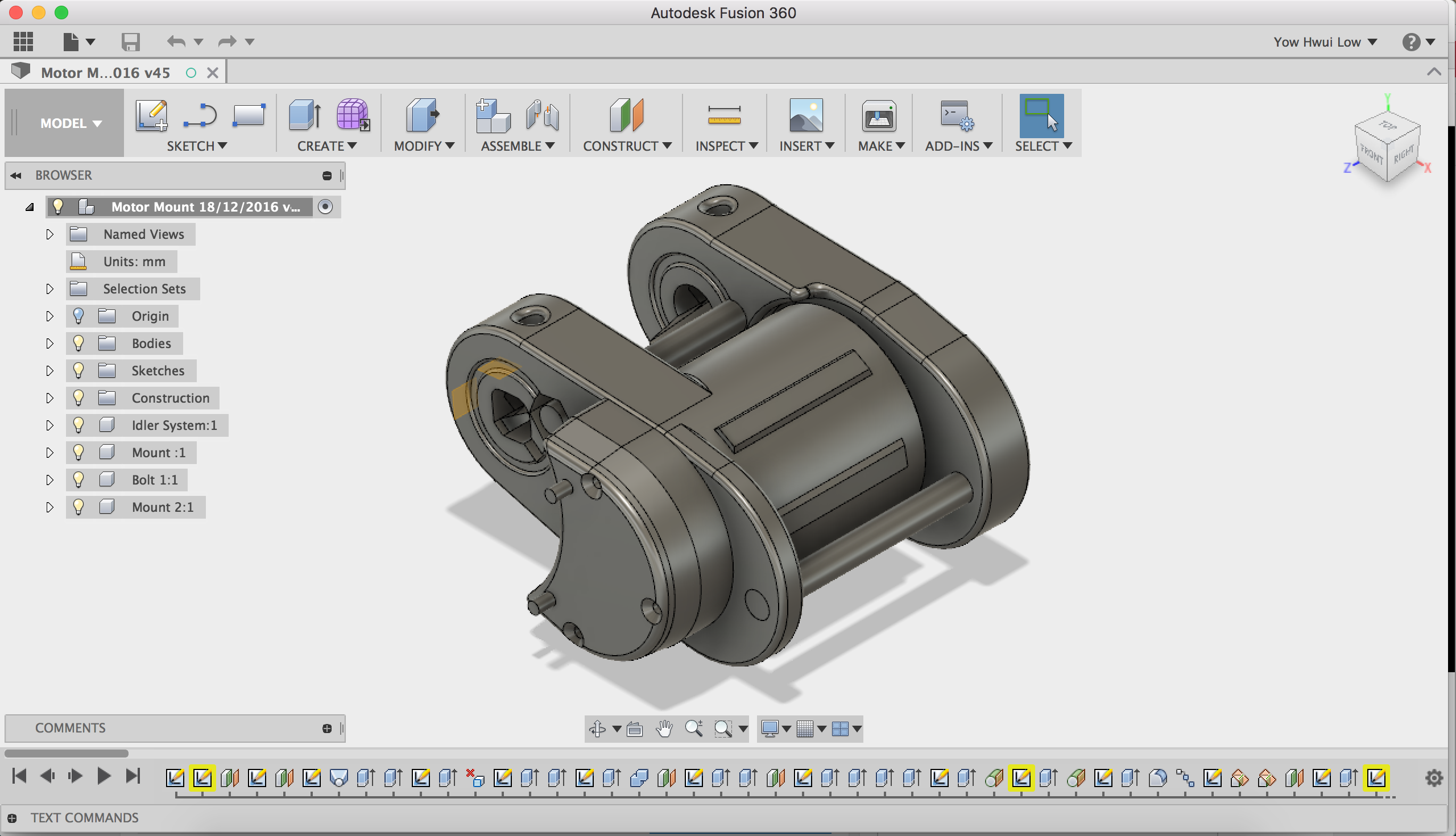
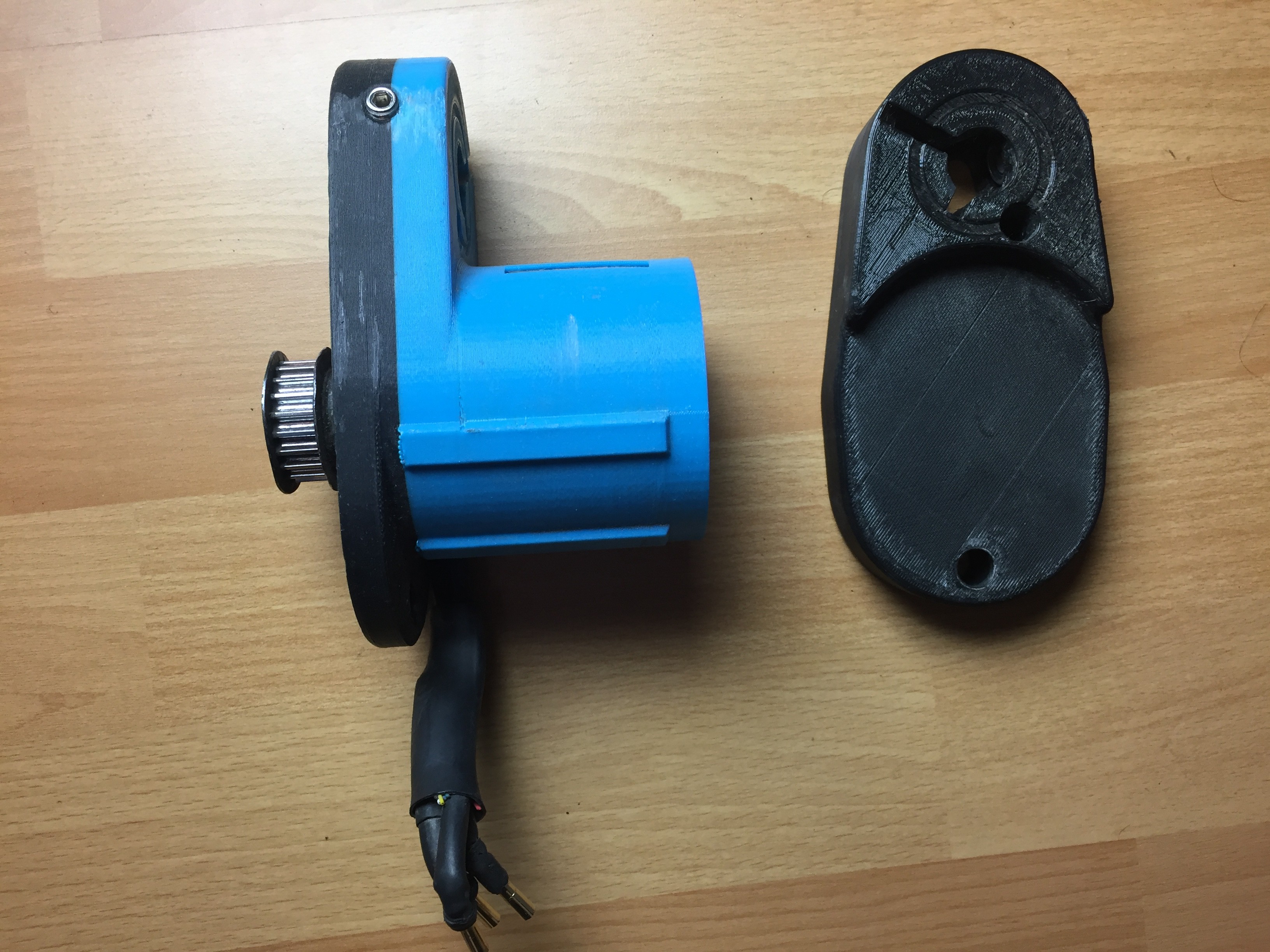
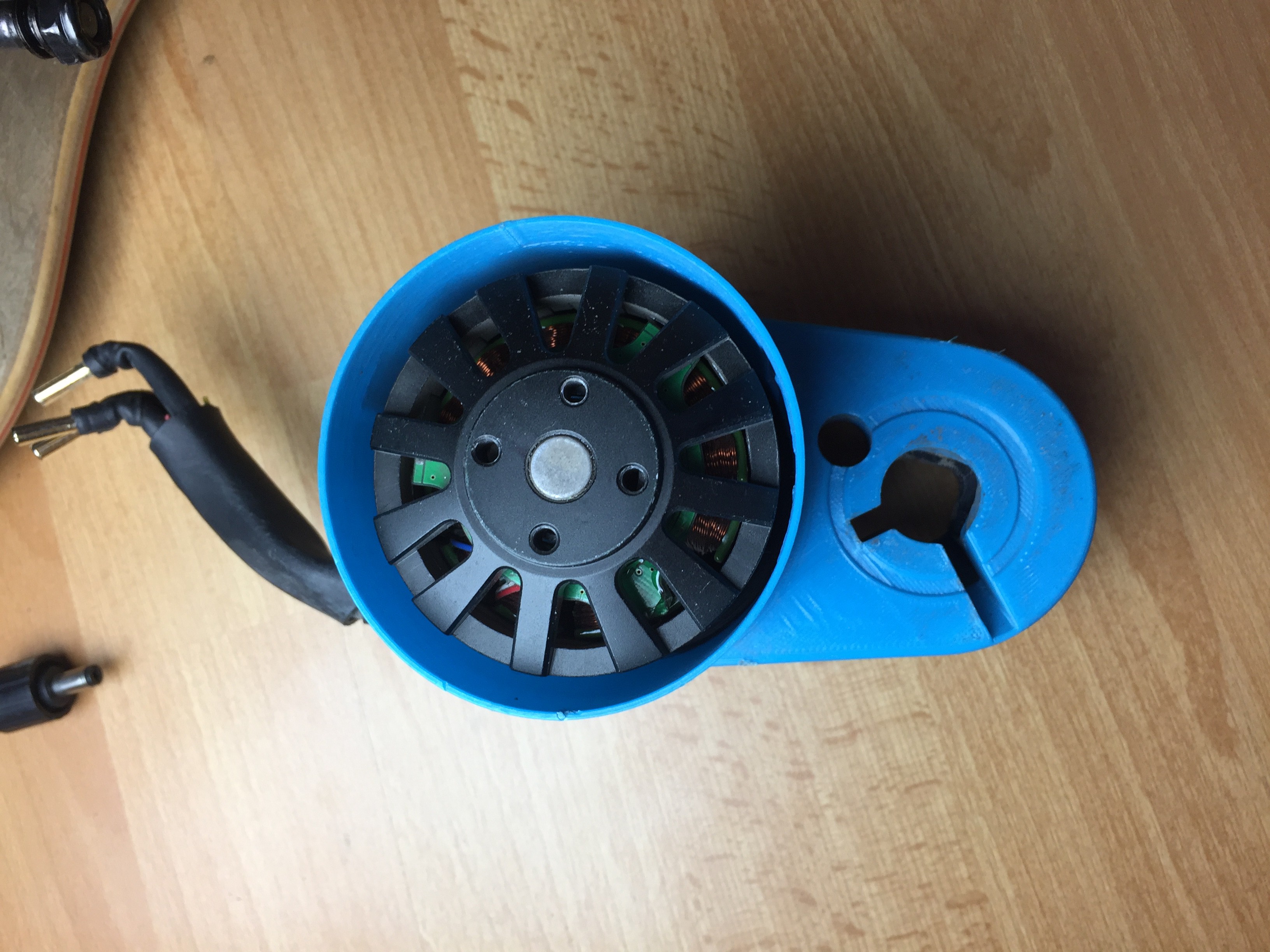
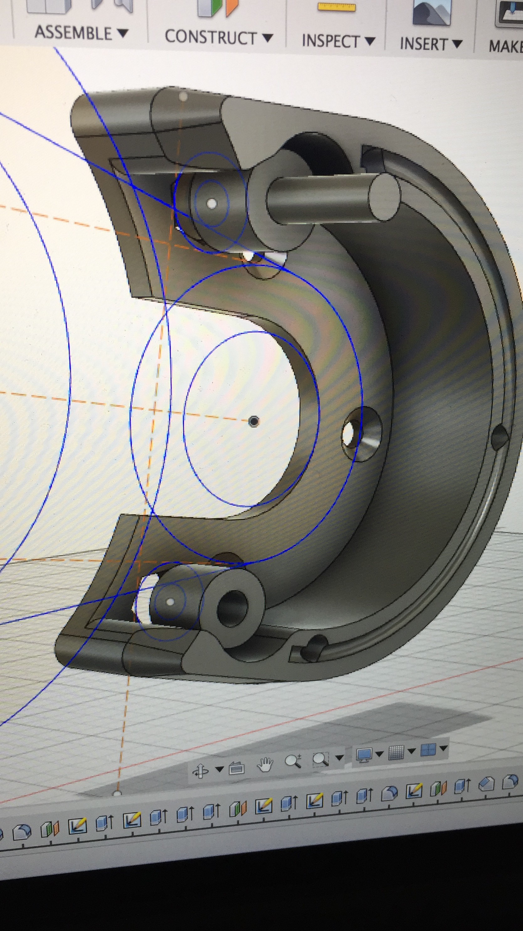
So, this is basically the most tedius part of the build if you are looking to design a motor mount out of ABS that can withstand large braking forces. The files can be found on my Thingiverse. It has been designed in such a way that you can remove it when you want to, but stays exactly where it is during riding. I wanted to test the limits of 3D-printed components and after 150 km (as of March 2017), I can say that it is holding up very well. Most builds use metal and weld the mount directly onto the trucks, which is fine too.
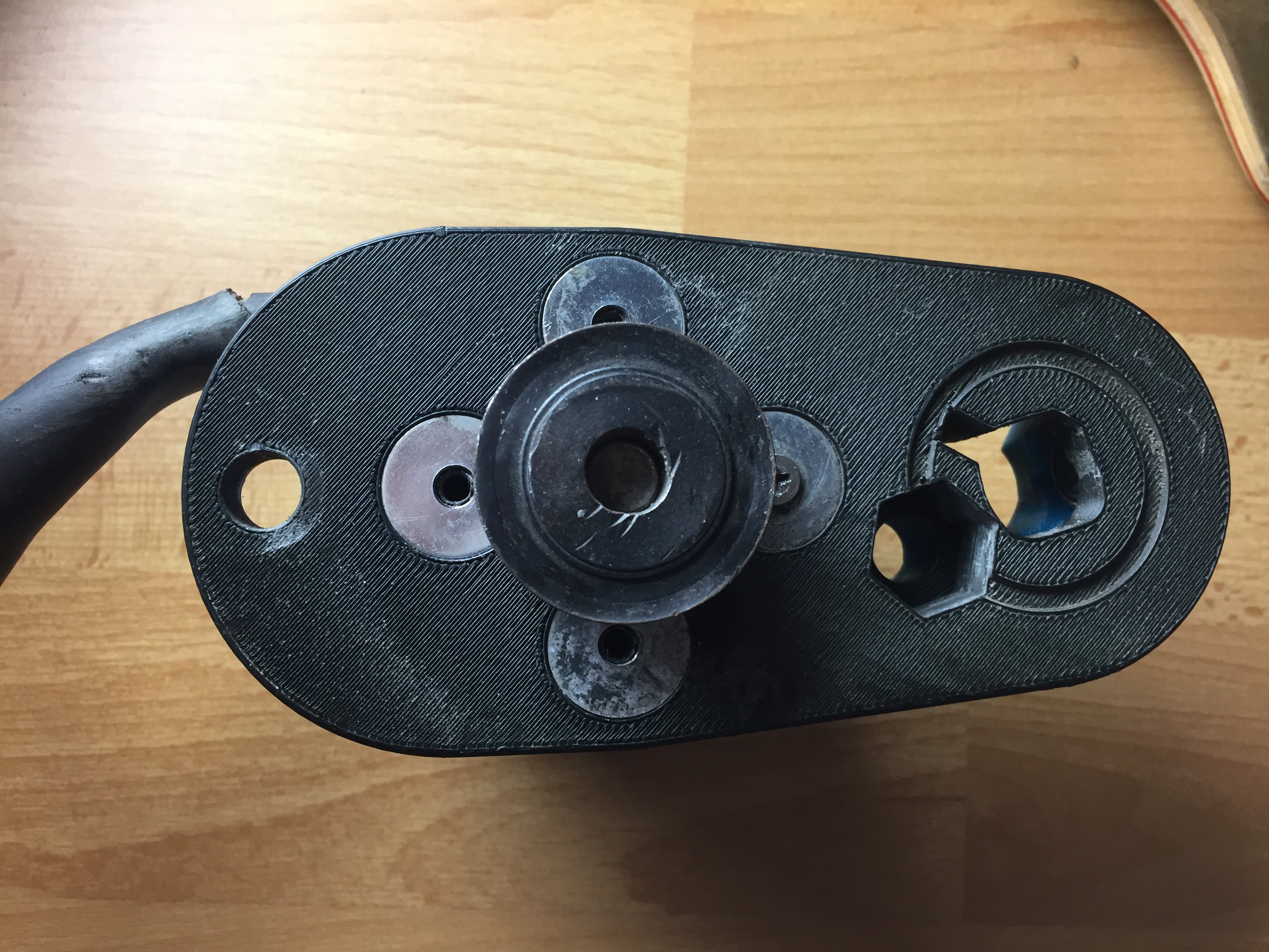
First, insert the 2 x M8 Nylock Nuts into the slots at the axle and screw in the 2 x M8 Set Screws from outside. This will help the mount grip onto the axle. Next, slide the motor into the mount and insert the 4 x M5 Washers into the mount. Next, use 1 x M5 x 16 mm Machine Screw on the axle side to hold the motor in place. The idler system will be using the other three holes in the next step. Now you can attach the pulley wheel to the motor to test out the fit. The BLDC motor I am using has a 10 mm shaft, so make sure the pulley also has the same bore size. Make sure there is no contact between the pulley wheel and the mount. Do not permanently mount the pulley yet, we still need to adjust it later.
Your Own Design
You can design your own mount by first drawing your trucks in CAD, this is quite a tricky process but after a few tries you will get it, don't give up too quickly. Next, you'll need to measure and record all the dimensions on your motor and trucks. Then, start drawing a primitive shape that will hold the components together. Once you feel quite confident, you can print your first prototype either on your own or using a service like 3DHubs and try to iterate from there. Constantly take notes on what to improve and incorporate it into your next design. On Fusion360 it took me 45 Versions and 6 printed prototypes to get to my end goal, you might require less tries. I also used Parametric Modelling to help me change the dimensions easily to get the perfect fit. Do not be discouraged, it is well worth it ;).
-
4Step 4
Step 4: Idler System
![]()
![]()
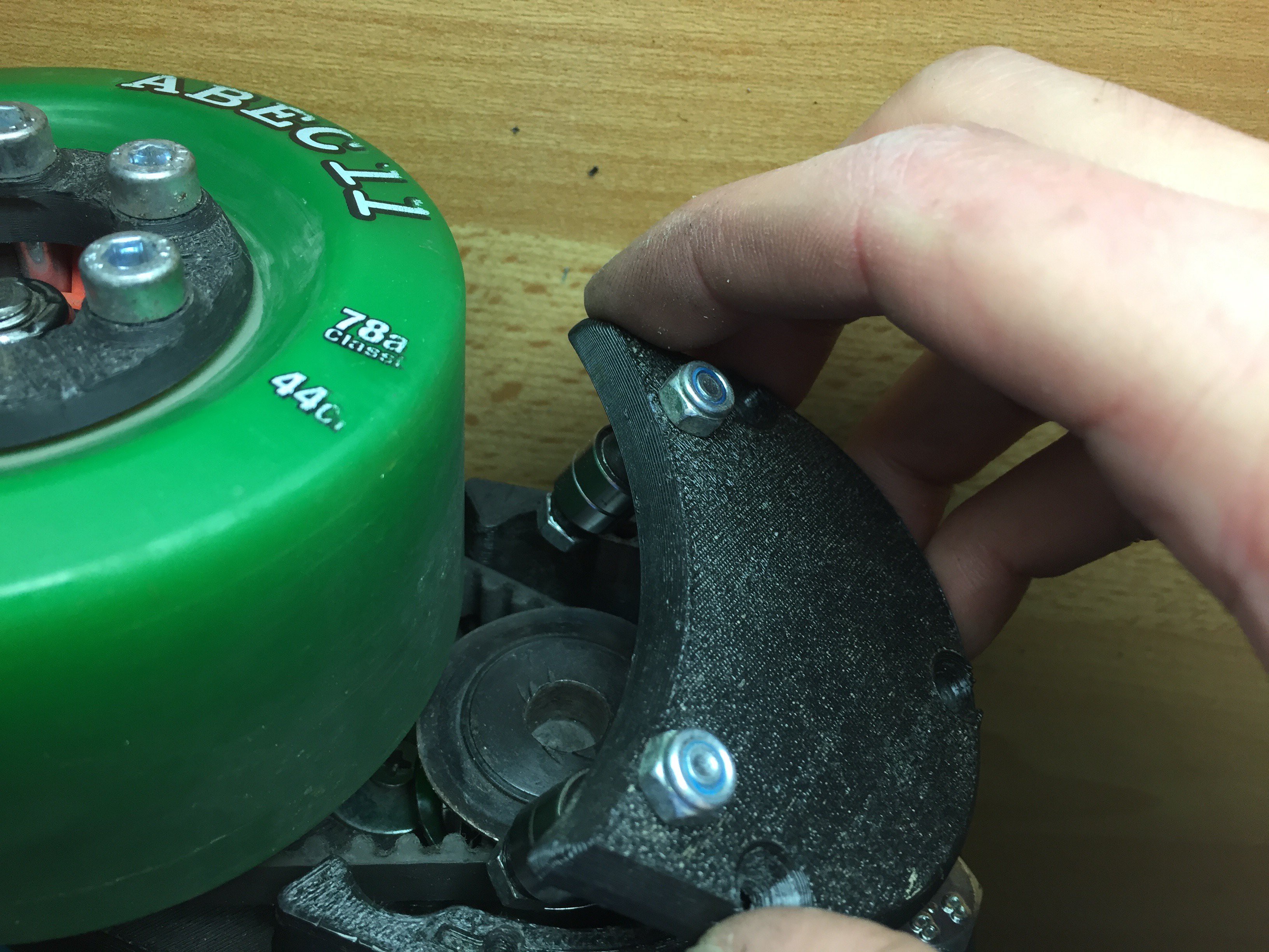
At this stage, your mount is already capable of accelerating but it will not be able to brake efficiently. This is where the idler system comes in. It makes sure that the belt has constant contact with the pulley wheel even during hard braking.
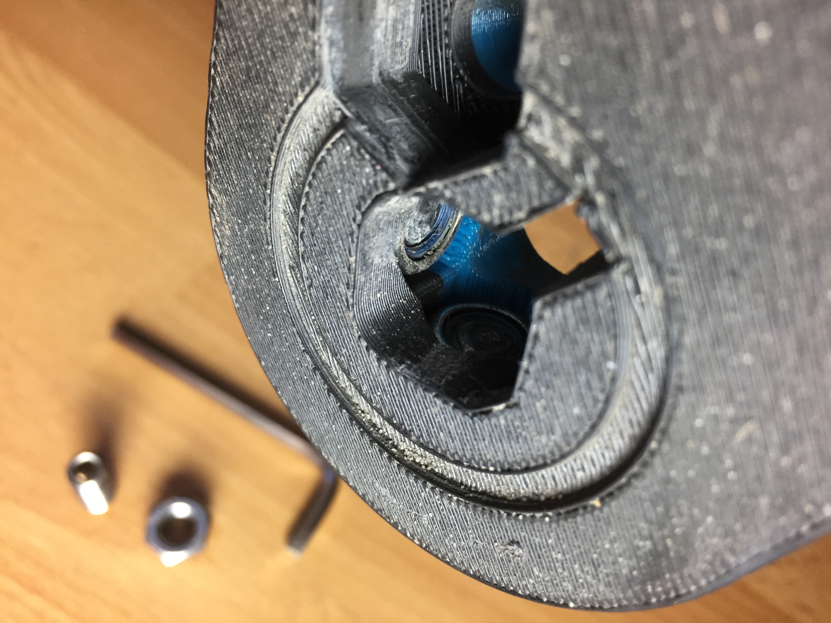
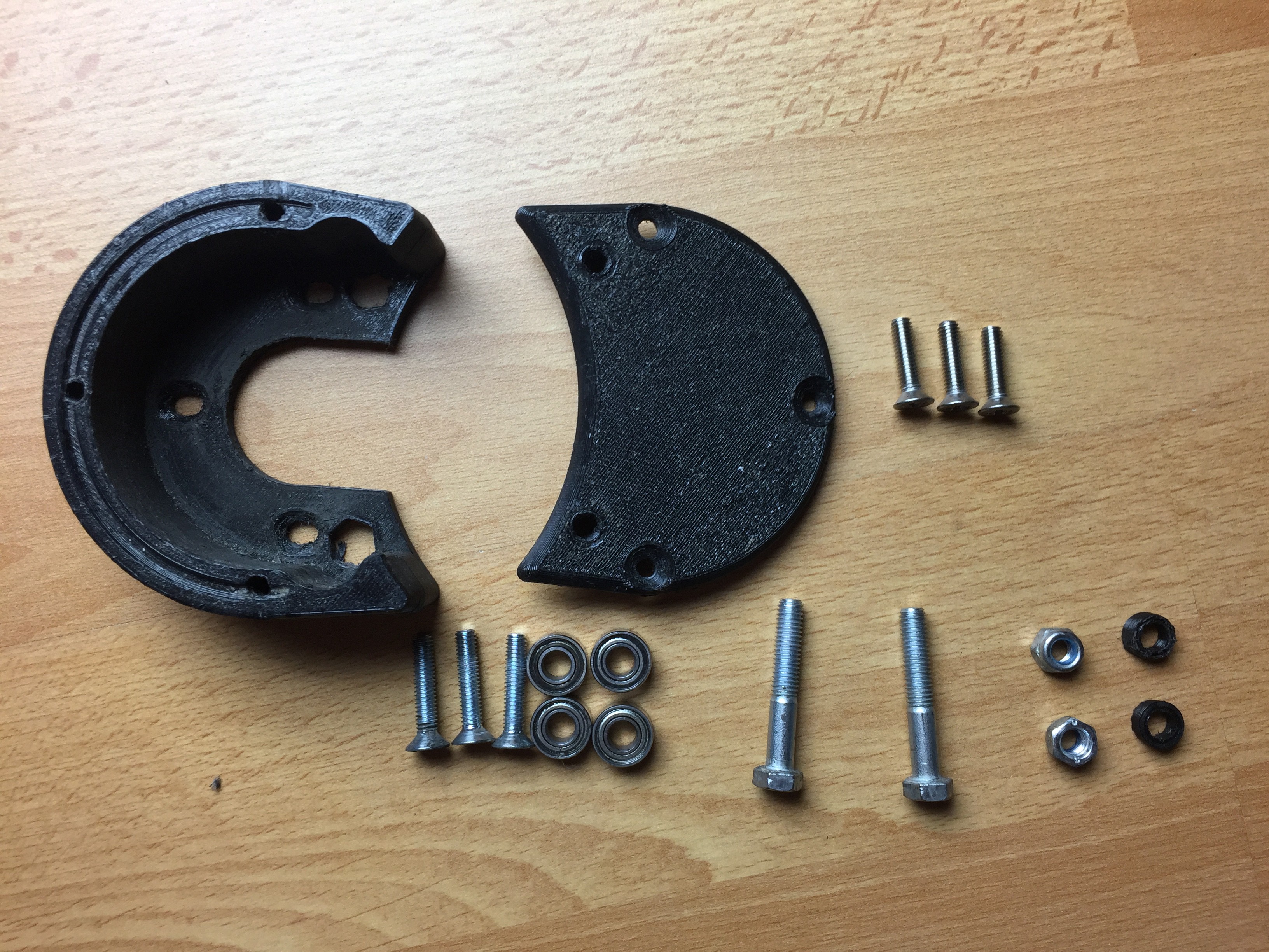
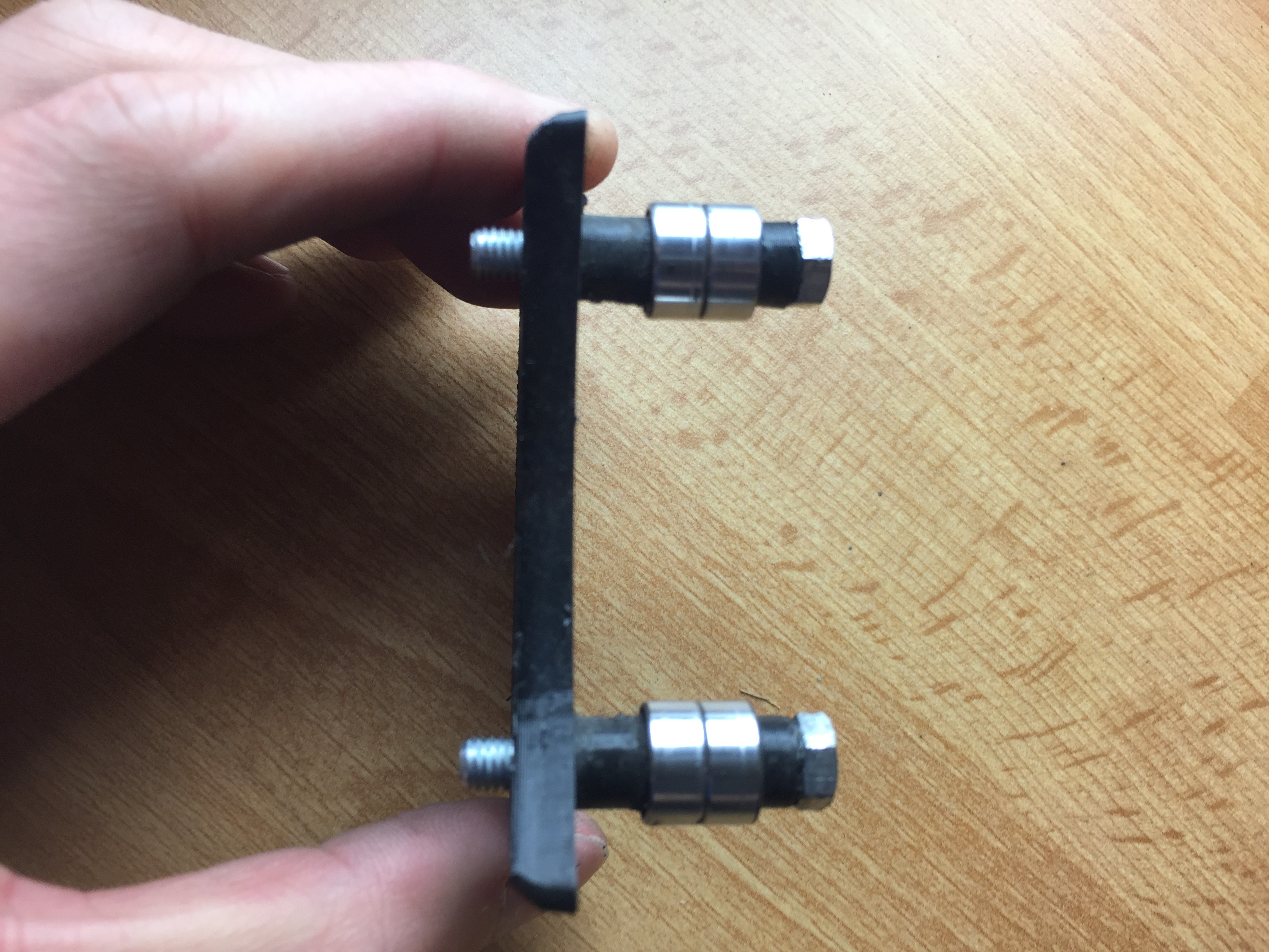
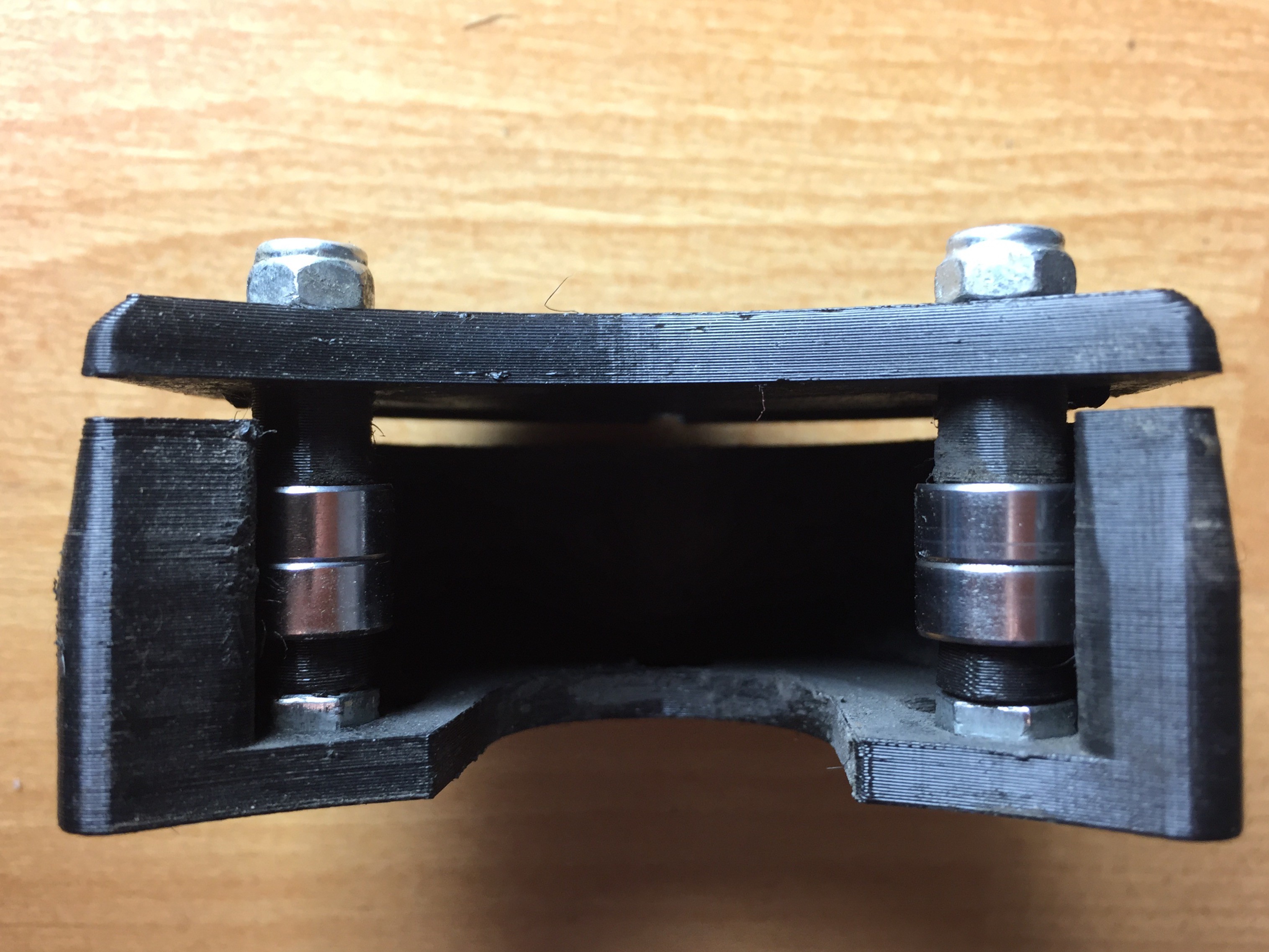
Take the 2 x M5 x 34 mm Hex Bolts and first insert the 3D-printed washers followed by the 4 x 5X11X5ZZ (685ZZ) Bearings as shown in the picture. Then screw them into the idler lid and position them so that the hex head fits into the idler body (Important!). Tighten the 2 x M5 Nylock Nuts and mount the idler body onto the mount using 3 x M4 x 20 mm Machine Screws. We are now ready to mount the drivetrain onto the rear trucks.
-
5Step 5
Step 5: Mounting The Drivetrain
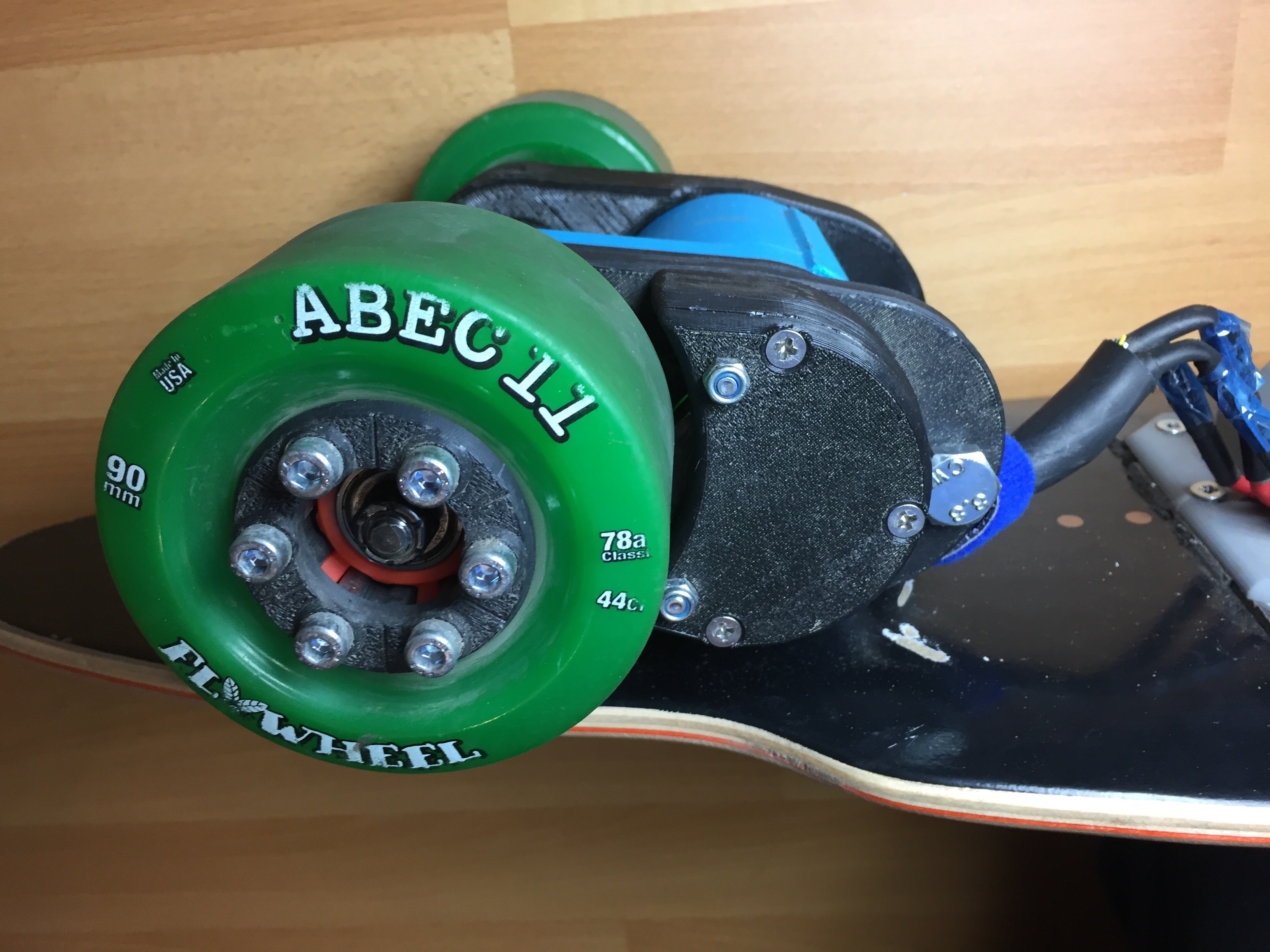
Push the motor mount onto the rear trucks as shown in the picture. Using a piece of cloth and hammer, gently tap the motor mount into position and tighten the M8 Set Screws. Do not over tighten the M8 Set Screws as we do not want too much stress to be concentrated in one area. Next, insert the same M8 Nylock Nuts and M8 Set Screws into the motor mount support/ stiffener and repeat the process. Lastly, using the M10 Bolts, Nuts and 3D-Printed Washer, attach the bolts through the mount and support. The motor mount is now secured axially and radially. The inner bolt (closest to the truck) can be secured tightly while the outer bolt (furthest away from the trucks) does not have to be too tight, it can be used to tighten the timing belt in the next step.
-
6Step 6
Step 6: Timing Belt and Idler System Positioning
![]()
![]()
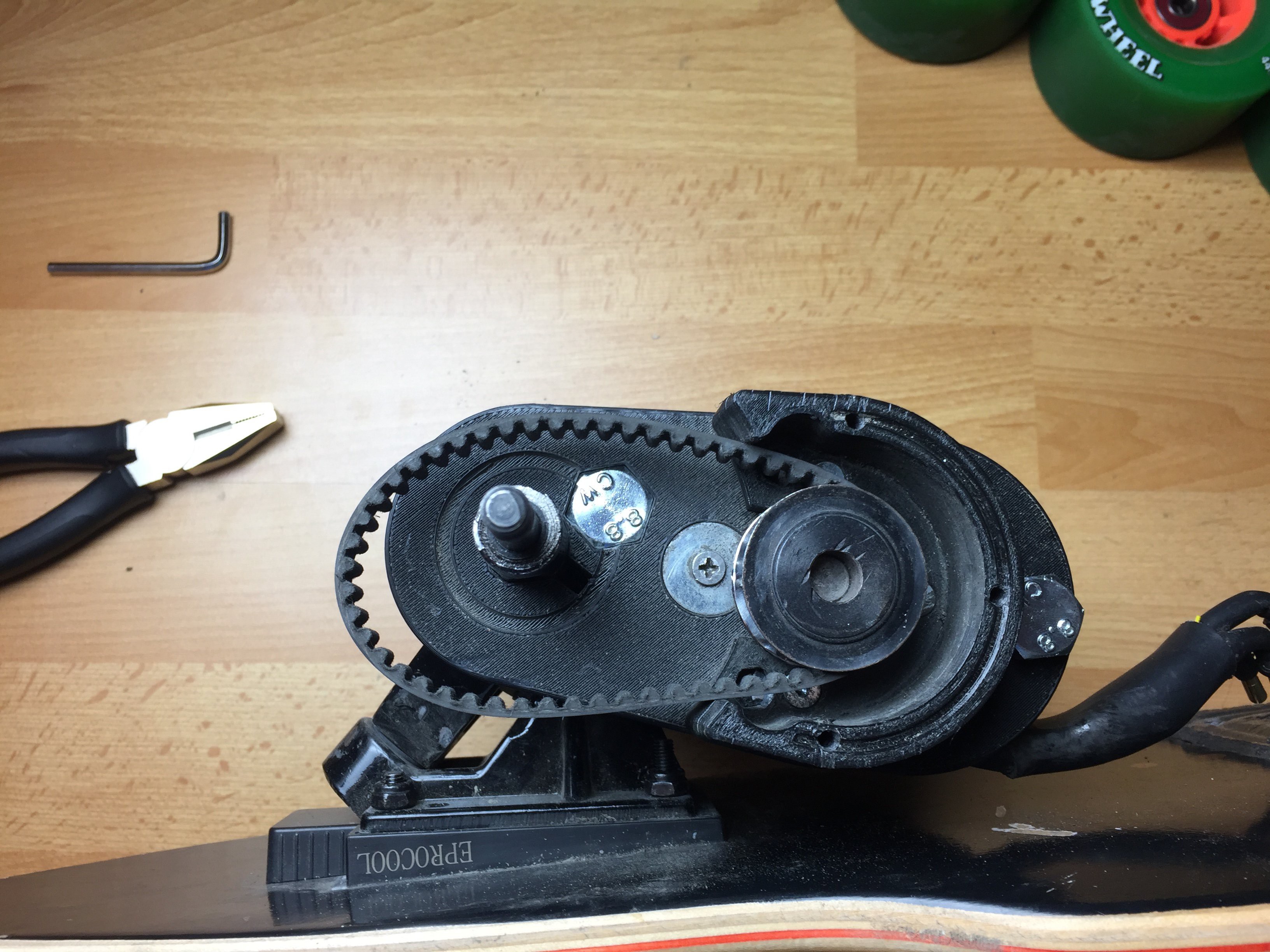
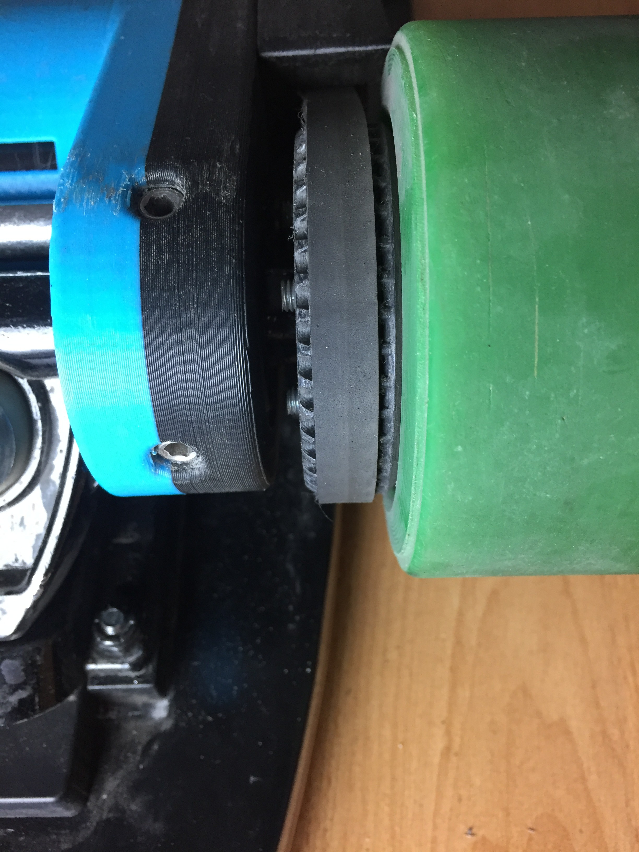
Now, it is important to correctly position the pulley to prevent premature wear of the timing belt. Attach the HTD5 9 mm wide 275 mm timing belt around the pulley and slowly turn the wheel gear in. Turn the wheel and let the belt slide to it's natural position. Position the pulley wheel accordingly to make sure the timing belt is centered as seen in the picture. Once the position is fixed, we can mount the pulley wheel permanently either by tightening the set screws with Loctite 243 or by adding Loctite 648 to the shaft. Beware that Loctite 648 is a very strong adhesive and you would need to heat up the pulley to over 250 degrees celcius in order to remove it. If you are not familiar with such procedures, I would recommend using a keyway and Loctite 243 on the set screws.
Next we need to complete the installation of the idler system. By pressing the belts together, we will be able to slide the idler bearings into the housing. Lightly tap the lid down with a hammer and a piece of cloth. We can then use the 3 x M5 x 16 mm Machine Screws to secure the lid. Tighten or loosen the outer M10 bolt to fine tune the tension of your timing belt. If you hear noises coming from the ball bearings or have a lot of resistance turning the wheels, the belt is too tight. The best tension is as loose as it can be without belt slippage during braking.
-
7Step 7
Step 7: Electronic Components
![]()
![]()
![]()
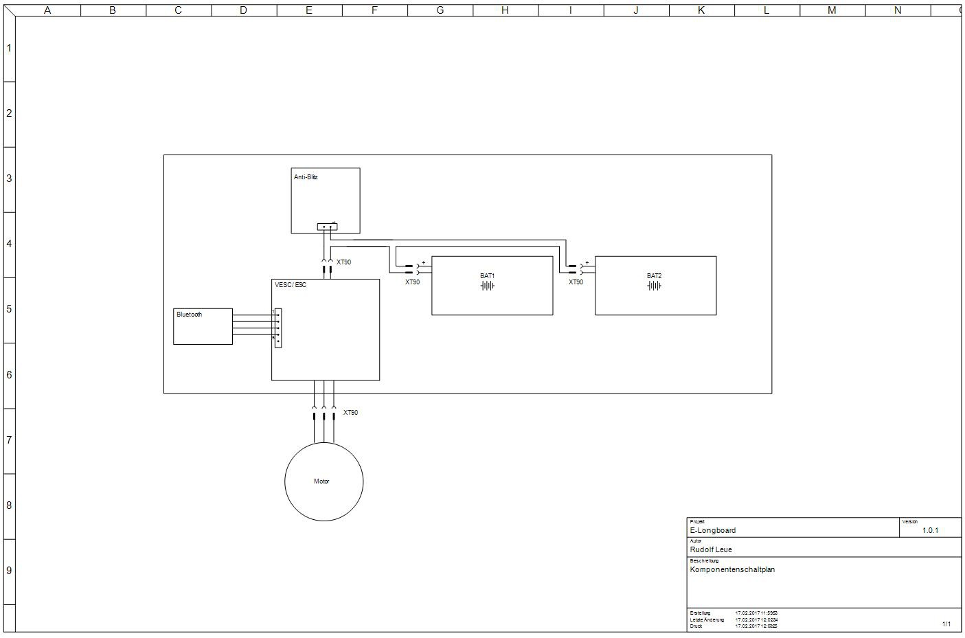
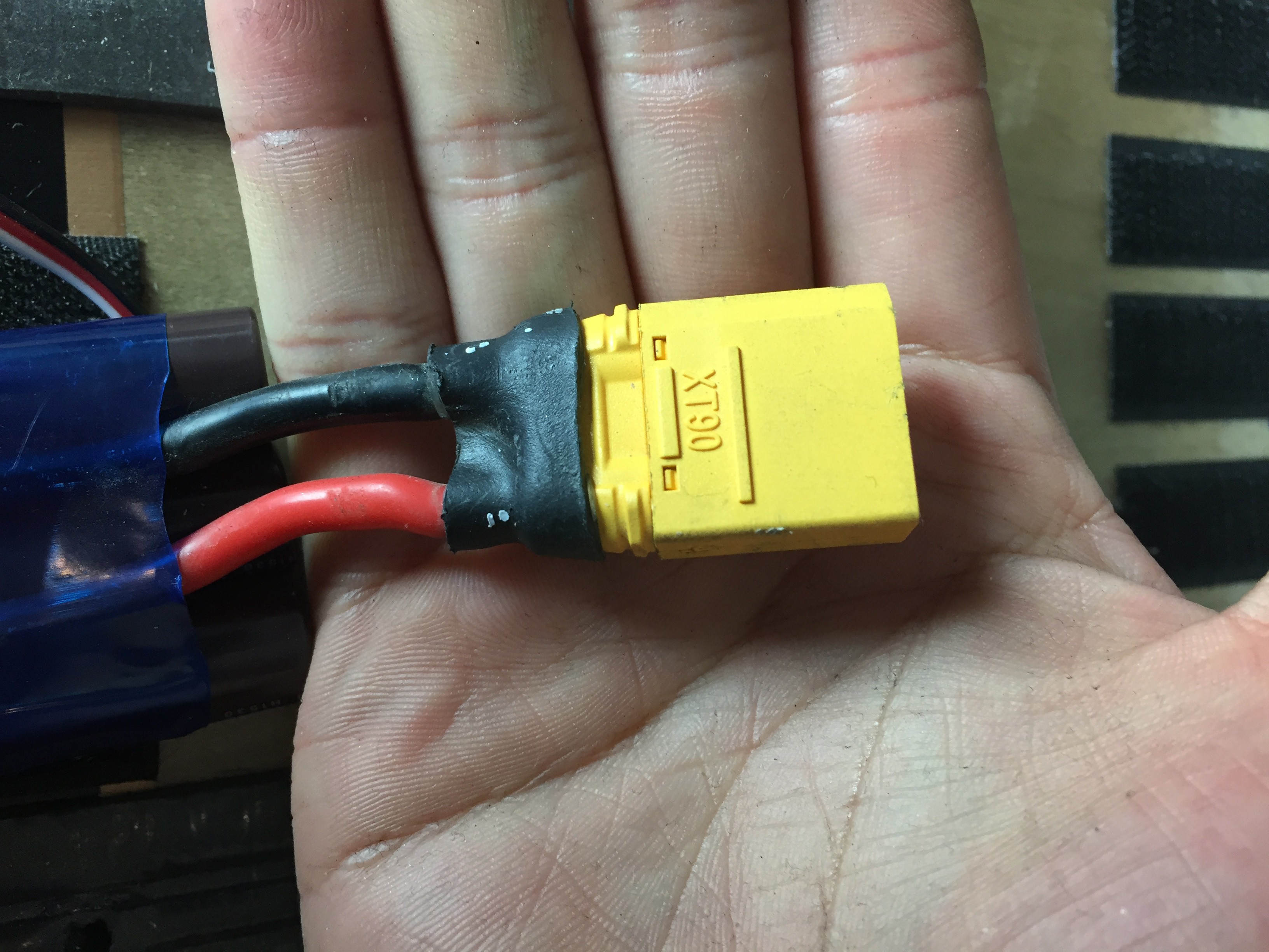
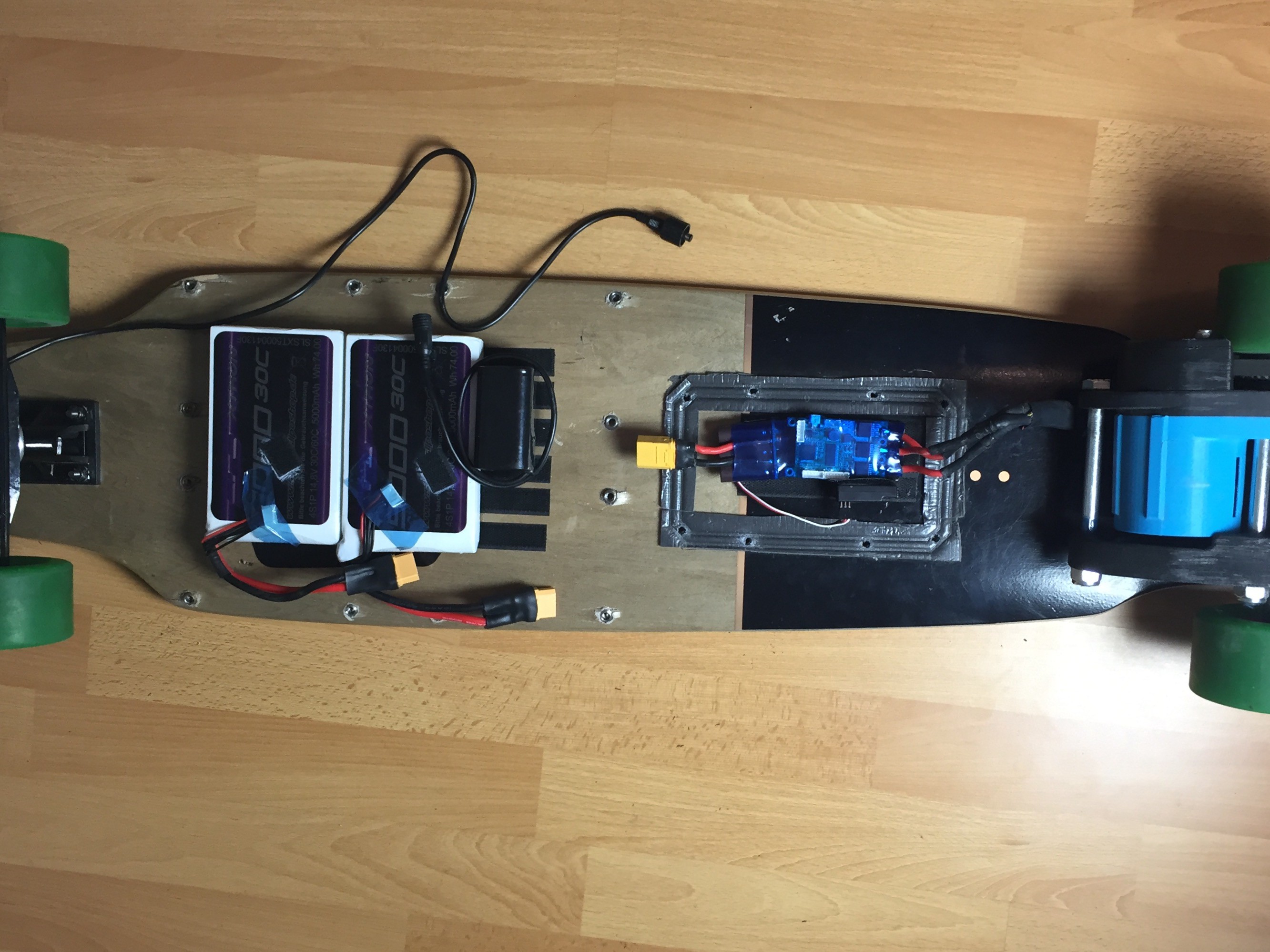
We are now done with the mechanical set up of our longboard. Next, we need to wire up the VESC to the batteries and receiver. It is a very straight forward procedure. Before we start, make sure all connectors are compatible. Solder the wire and connectors as well as using heat shrink to cover any live wires. Here we are using 10 AWG wires and XT-90 connectors to ensure that nothing gets too hot even when we are going up steep hills and the motor is drawing high amperage.
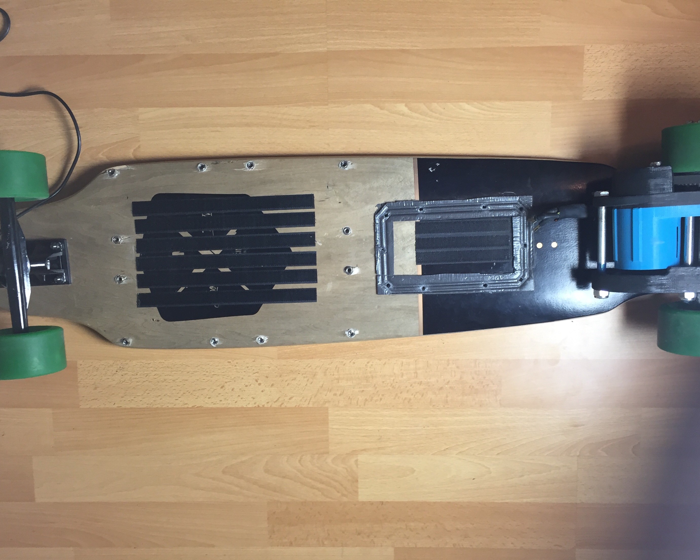
Wire up the system according to the scematic (Thanks Rudolf!). The two 4S batteries are connected in series, giving us an 8S set up (max. 33.6 Volts). The VESC control handle up to 10S, or 42 Volts. For the receiver you can either use a Bluetooth or 2.4 GHz receiver. This can be set up in our VESC later on. I made a rough outline of the position of my components and attached high strength velcro to my board and components.
I will not cover the set up of the VESC in this tutorial as there is already a lot of content on Youtube and Electric Skateboard Forums. Anyone without any prior programming skills can set up the VESC easily with the open source BLDC GUI tool. Make sure you know what firmware is on your VESC when you buy it and what software to use. Your vendor will usually provide these details. I have read that incompatible firmware can cause you to fry your VESC so do some research beforehand. For me my VESC was already loaded with firmware and I only needed to download the right BLDC tool for configuration.
Few things we need to keep in mind, write down these specifications and insert them into your VESC config.:
- Max. allowable amperage of your motor
- Max. allowable discharge of your LiPo batteries (Discharge rate (C-rating) * Capacity (mAH))
- Max., min. voltages of each battery cell. (Usually 3.5 V min and 4.2 V max)
Be aware during initial testing of acceleration and braking, always wear a helmet and accelerate/brake gradually. The acc./braking values can be changed depending on your ride style in the VESC but it requires some experimentation.
-
8Step 8
Step 8: Optional Upgrades
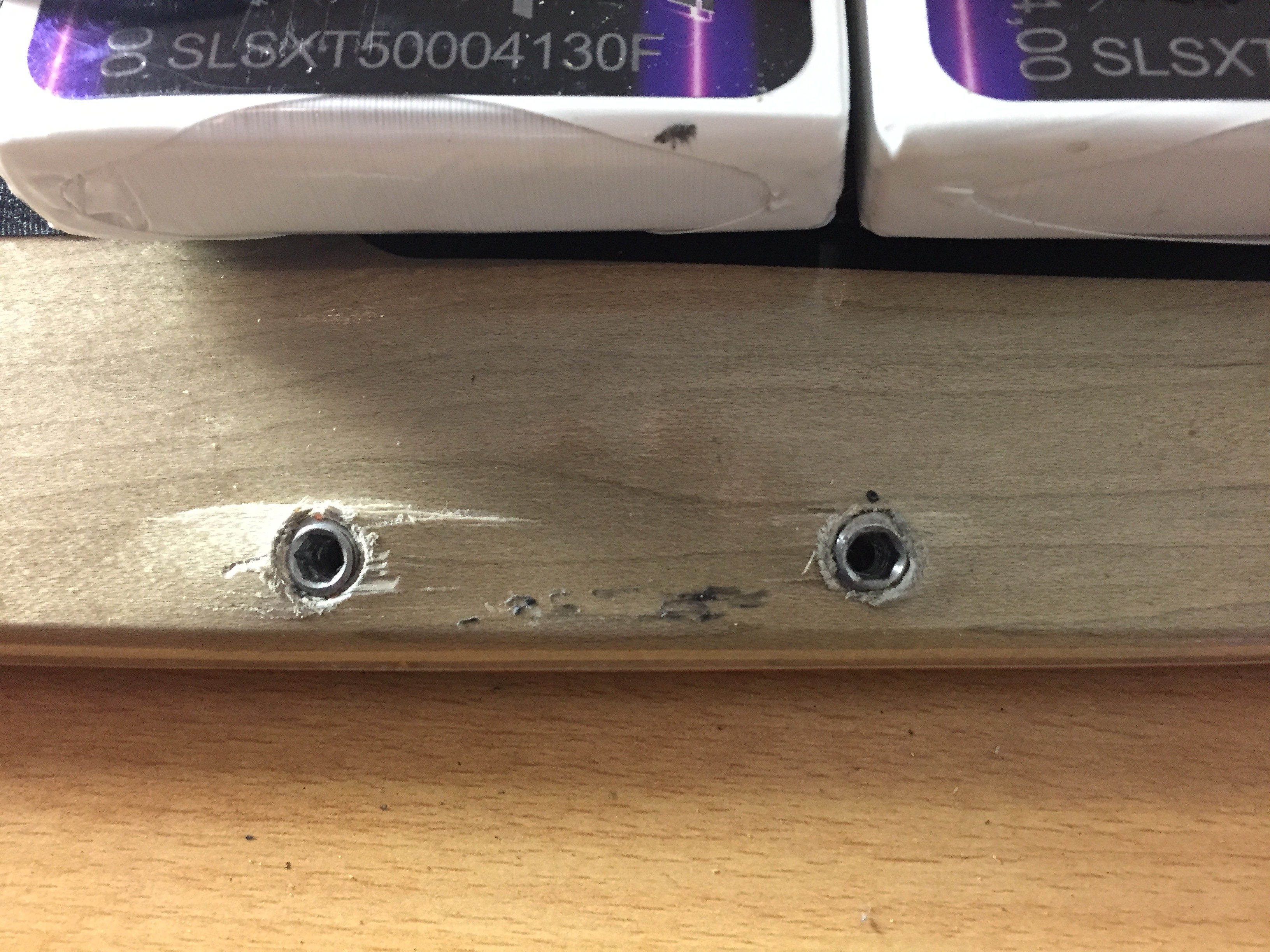
For my board I also printed a housing for the battery and VESC, the files are also on my Thingiverse. Please note that the battery housing is modelled according to the curvature of my RAM longboard. It is divided into four pieces in order to fit a 200 x 200 mm printer and can be fused together using some ABS glue (Acetone+ABS). The VESC housing is modelled to fit any board as it is quite small. Threaded inserts for hard wood were used to keep the screws in place.
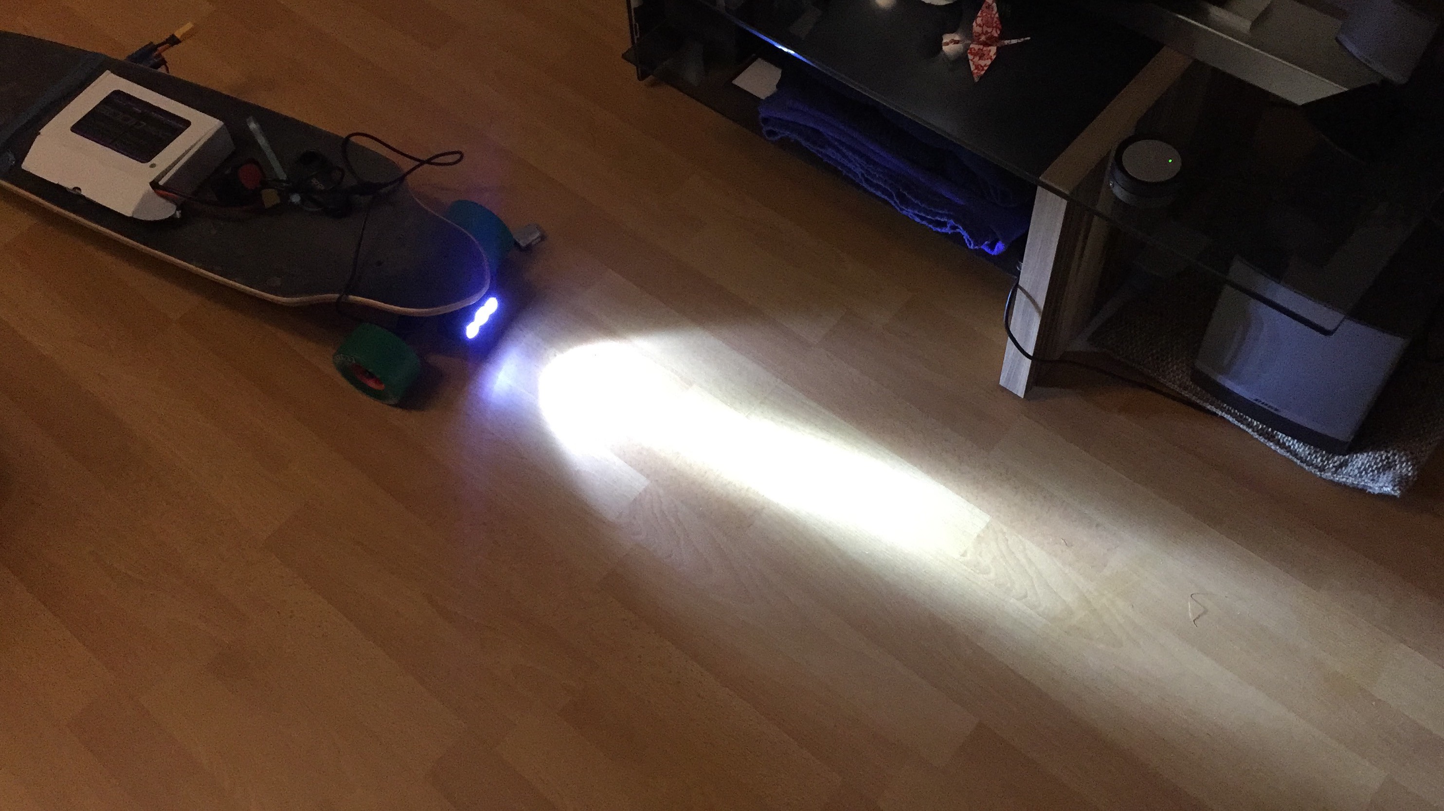
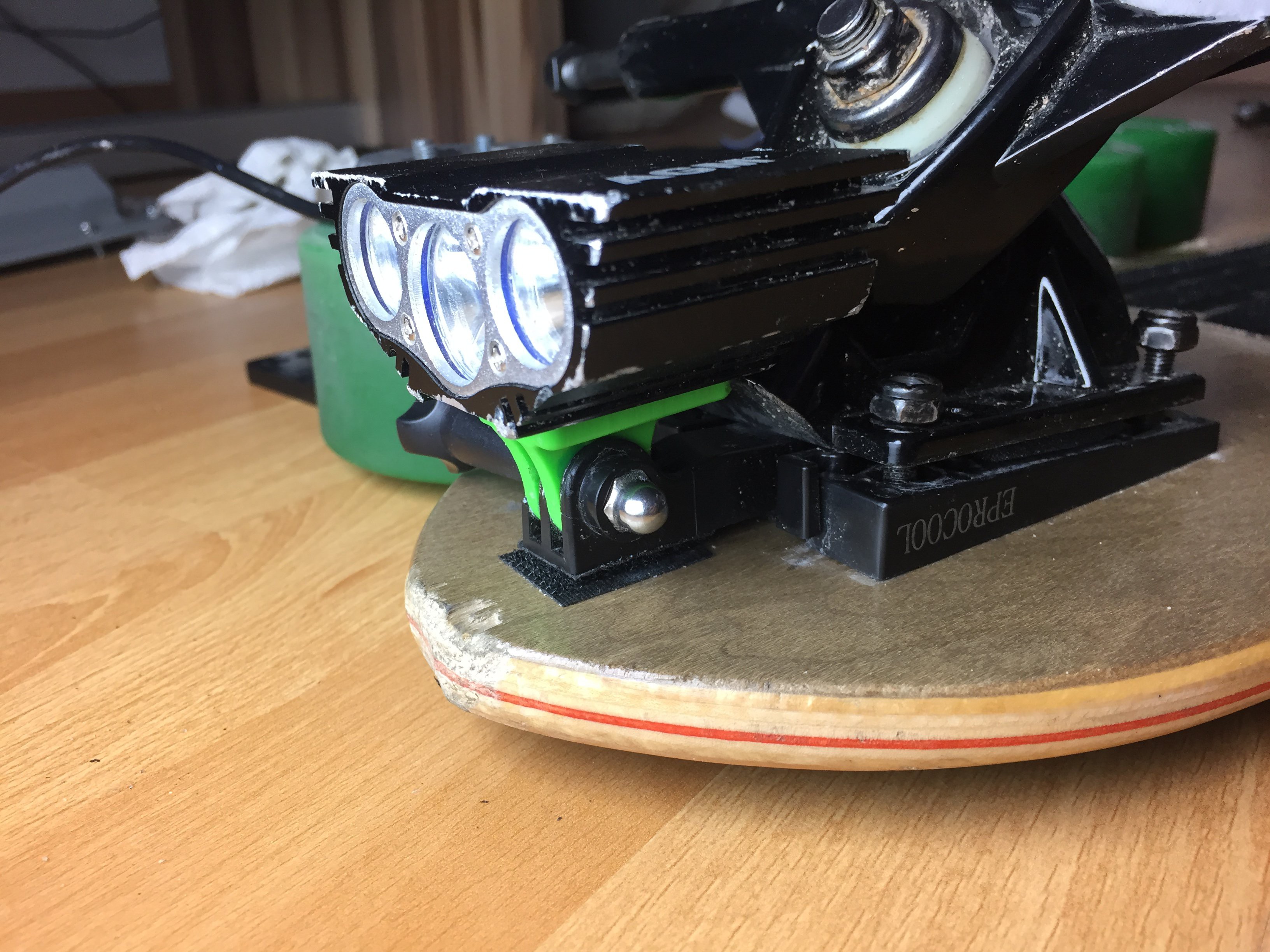
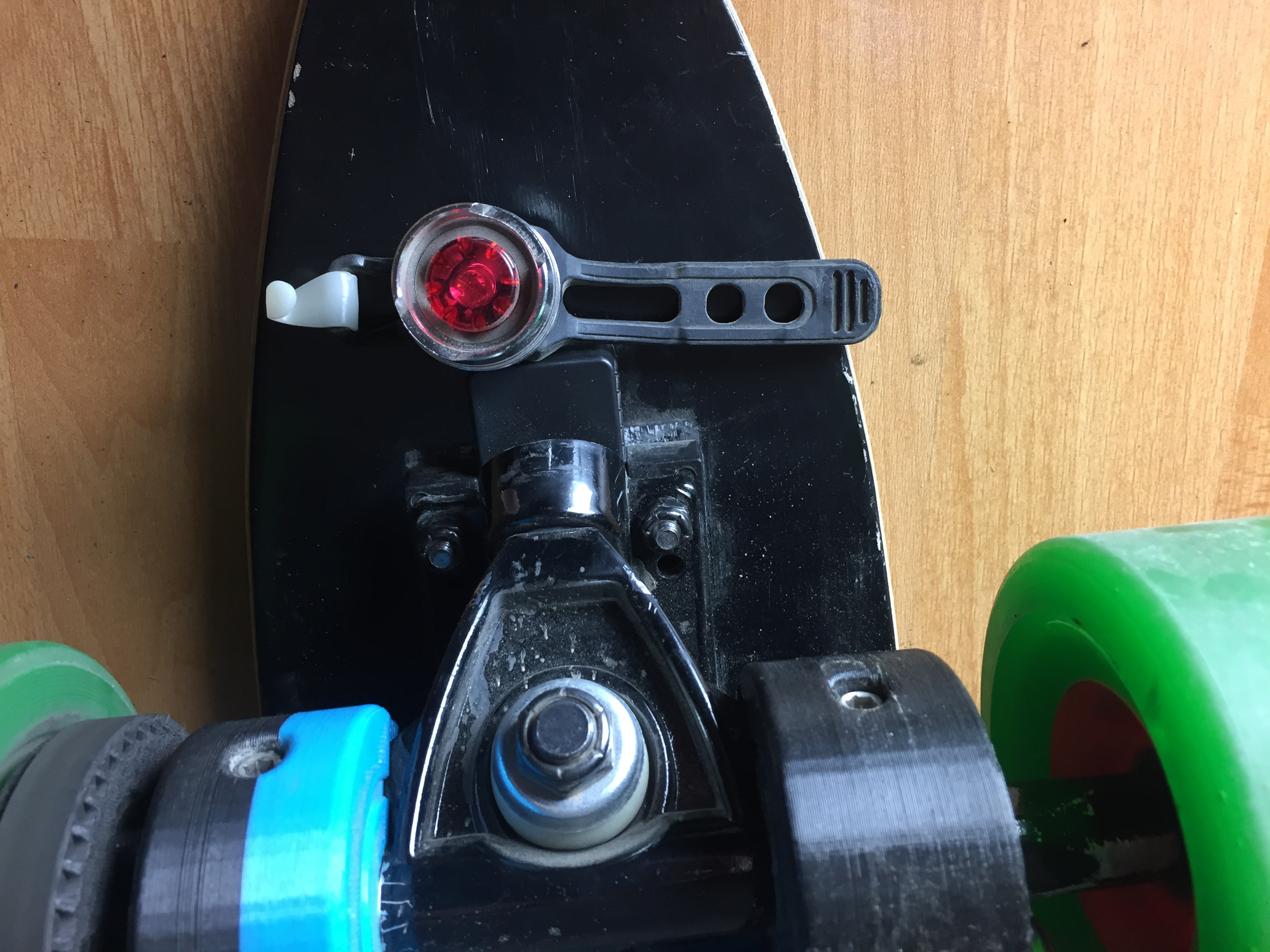
I also added AGM Cree X3 10 W Lights for night riding. Files here (Designer: John21). Make sure you print them in the right orientation (standing up), if not it breaks easily.
A voltmeter was also added so I know how much battery I have left. It is important not to drain the batteries below 3.5 V per cell as a permanent irreversible chemical reaction will occur and your capacity will decrease. Also, use a balance charger to make sure all cells are at the same voltage after charging.
3D-Printed Electric Longboard
Fully 3D-printable electric longboard drivetrain with built-in idler system.
 yowhwui




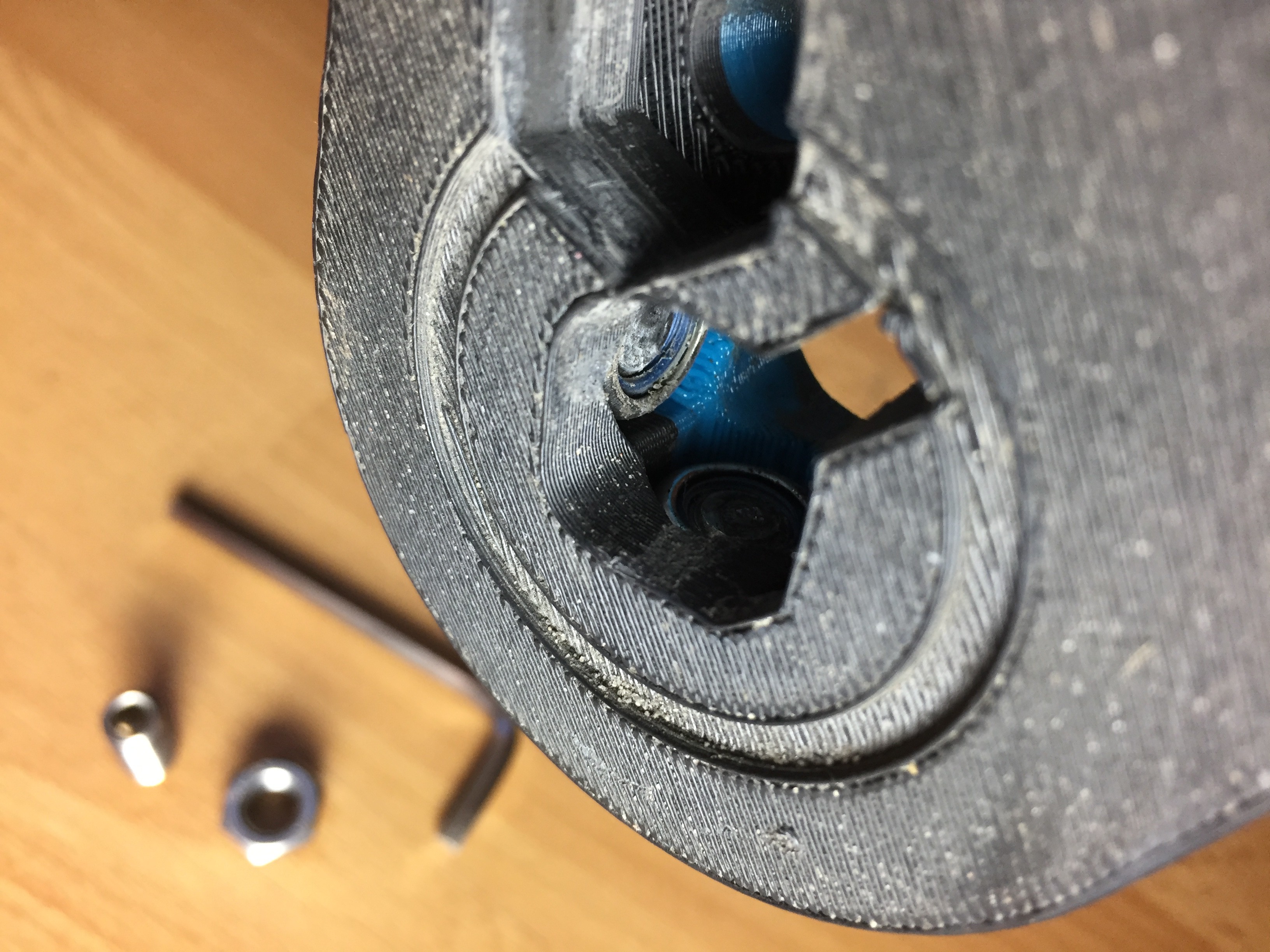
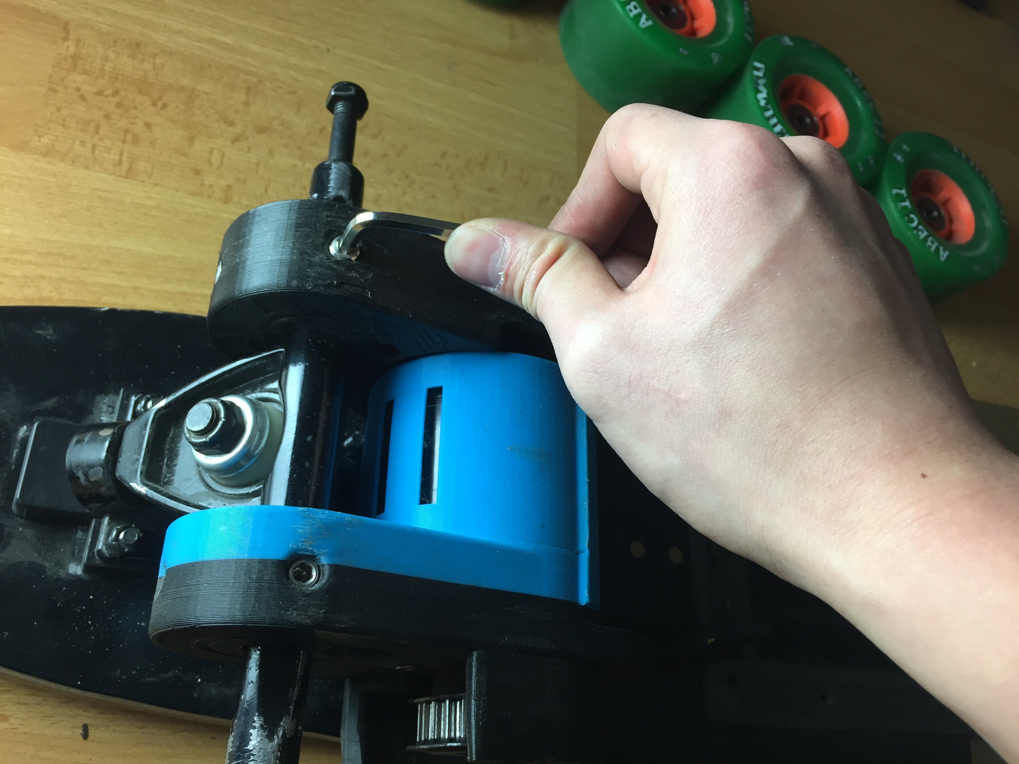
 Push the motor mount onto the rear trucks as shown in the picture. Using a piece of cloth and hammer, gently tap the motor mount into position and tighten the M8 Set Screws. Do not over tighten the M8 Set Screws as we do not want too much stress to be concentrated in one area. Next, insert the same M8 Nylock Nuts and M8 Set Screws into the motor mount support/ stiffener and repeat the process. Lastly, using the M10 Bolts, Nuts and 3D-Printed Washer, attach the bolts through the mount and support. The motor mount is now secured axially and radially. The inner bolt (closest to the truck) can be secured tightly while the outer bolt (furthest away from the trucks) does not have to be too tight, it can be used to tighten the timing belt in the next step.

Discussions
Become a Hackaday.io Member
Create an account to leave a comment. Already have an account? Log In.