 Arnov Sharma
The whole idea behind this project was to make my own MOSFET-based H-bridge motor driver instead of relying on modules like the L293D or L298N. I wanted something I could drop directly into my own PCB designs, especially for a robot rover project I’m building soon. Space is tight on that rover, so I’ve been experimenting with compact drivers—and at some point I thought, why not just make my own?
So this article is basically the process of how I designed and built this little motor driver from scratch. Let’s jump into how it all came together.
MATERIALS REQUIRED
These were the components I used in this build:
- Custom PCBs (provided by JLCPCB and JLCCNC)
- A04406 Mosfet IC
- 10K Resistor
- 5R1 Resistor
- CON6 vertical male header pin
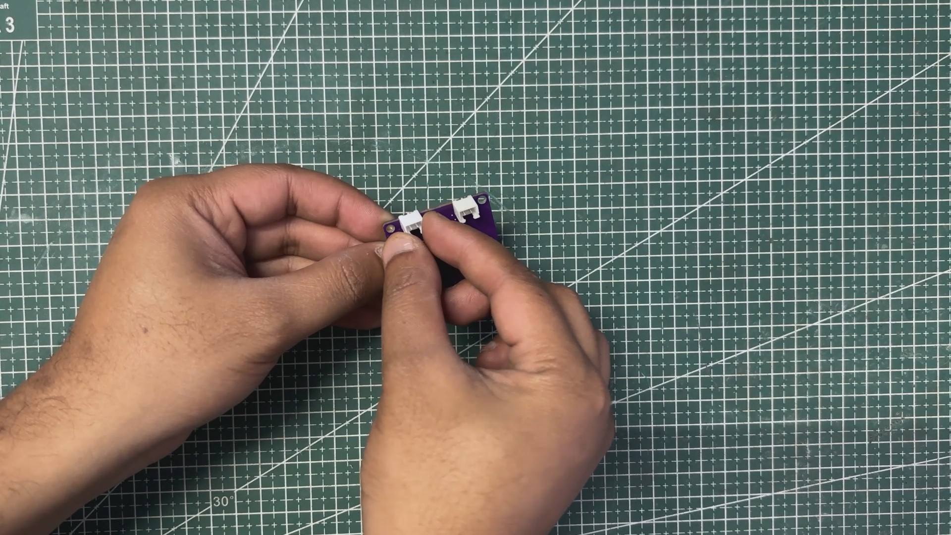
- CON2 JST connector
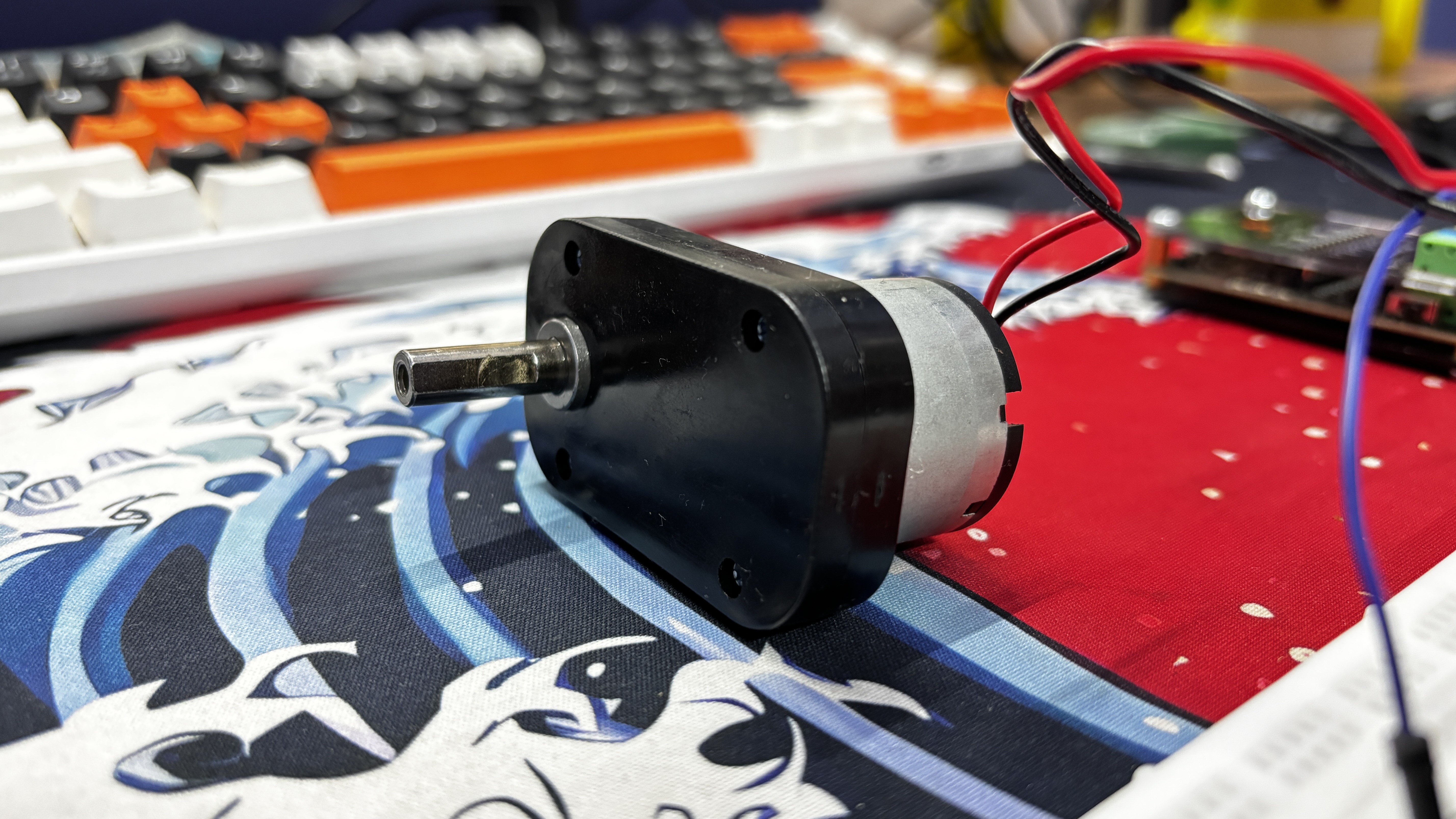
- 5V operating Gear Motor
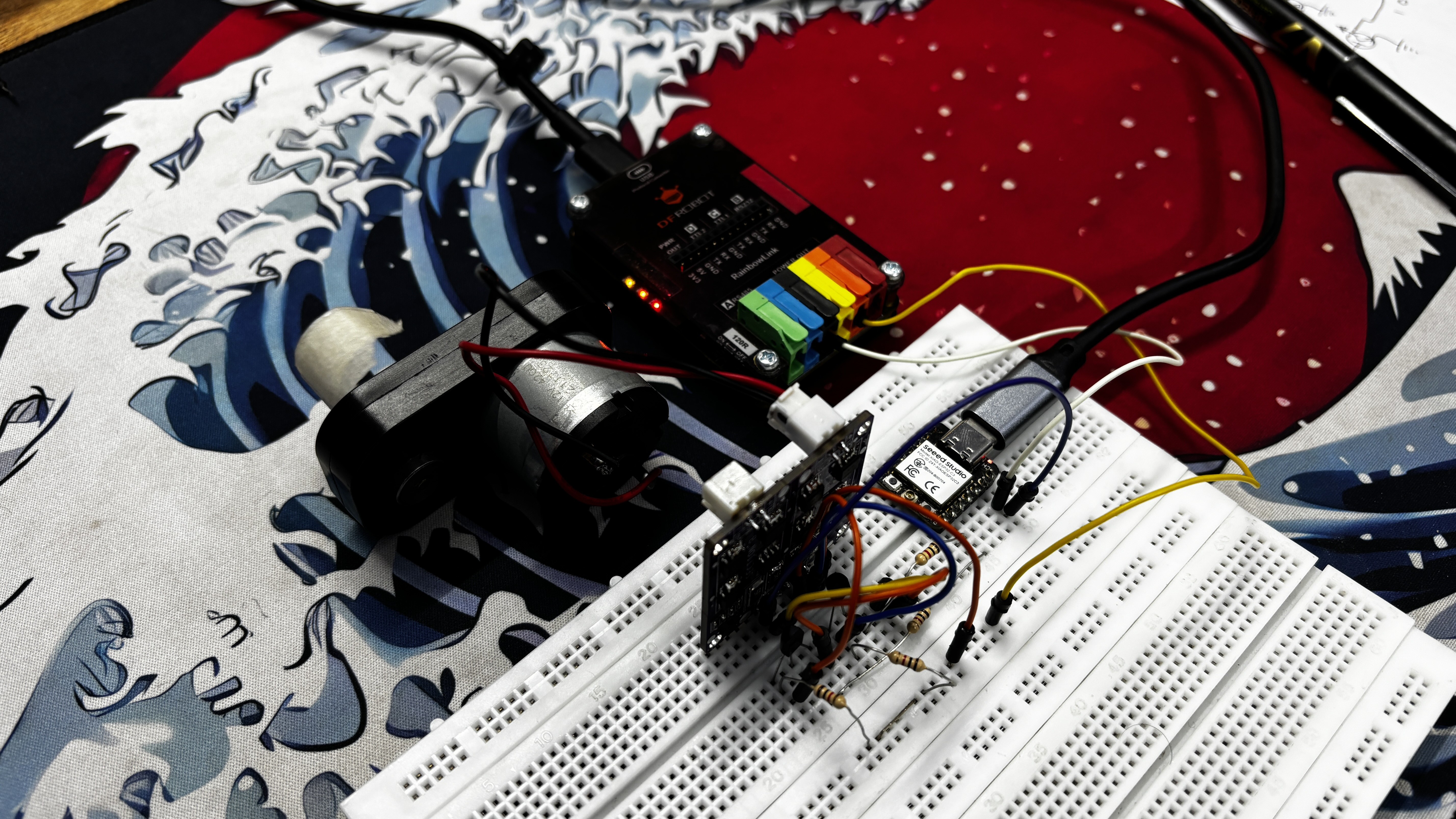
- Breadboard
- Push Buttons
- Connecting wires
- Microcontroller—XIAO ESP32 C6 (any MCU can be use here)
CIRCUIT
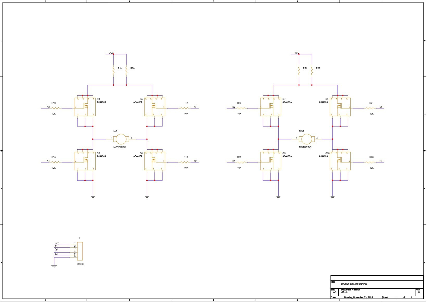
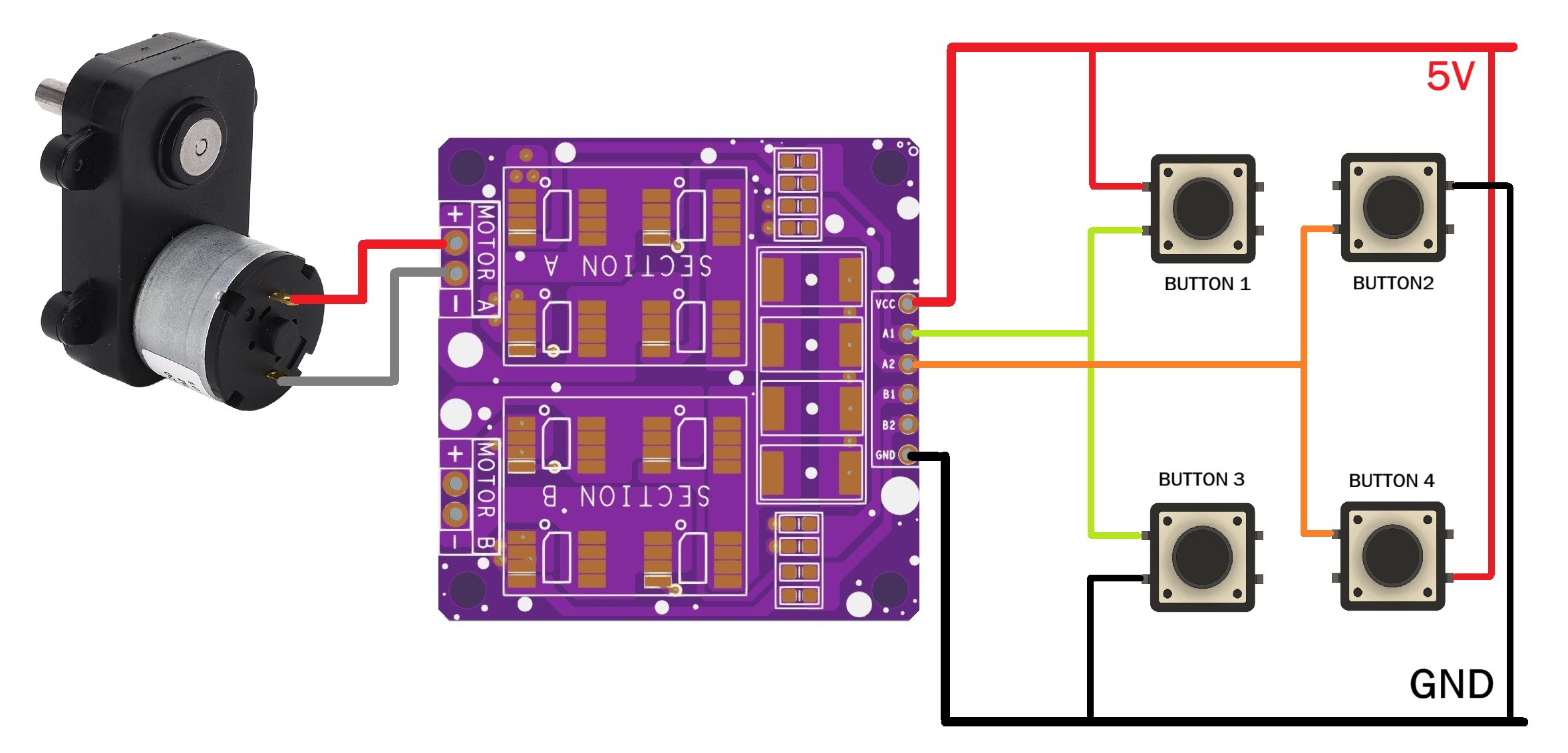
We first started by preparing the schematic for the project, and the design is fairly simple. The core of the circuit is an H-bridge made using four AO4406 N-channel MOSFET ICs—MOSFET 1, MOSFET 2, MOSFET 3, and MOSFET 4—with the motor placed in the middle.
MOSFET 1 and MOSFET 2 form the high-side pair. The drains of both are tied together and connected to VCC. Their sources go to the two terminals of the motor.
On the low side, the drain of MOSFET 3 connects to the same motor terminal as the source of MOSFET 1, and the drain of MOSFET 4 connects to the motor terminal paired with the source of MOSFET 2. The sources of MOSFETs 3 and 4 are both tied to GND.
Each MOSFET gate is paired with a 10K resistor. The gates of MOSFET 1 and MOSFET 4 share one input line, while the gates of MOSFET 2 and MOSFET 3 are linked together on the second input line. These two inputs act as A1 and A2. By toggling A1 and A2 HIGH or LOW, we decide the direction of current flow through the motor, which in turn controls the rotation direction.
We then duplicated this entire H-bridge to create a second identical driver for the second motor.
To keep everything neatly connected, we added a CON6 header that brings out VCC, GND, the two inputs for Motor 1 (A1 and A2), and the two inputs for Motor 2 (B1 and B2).
PCB DESIGN
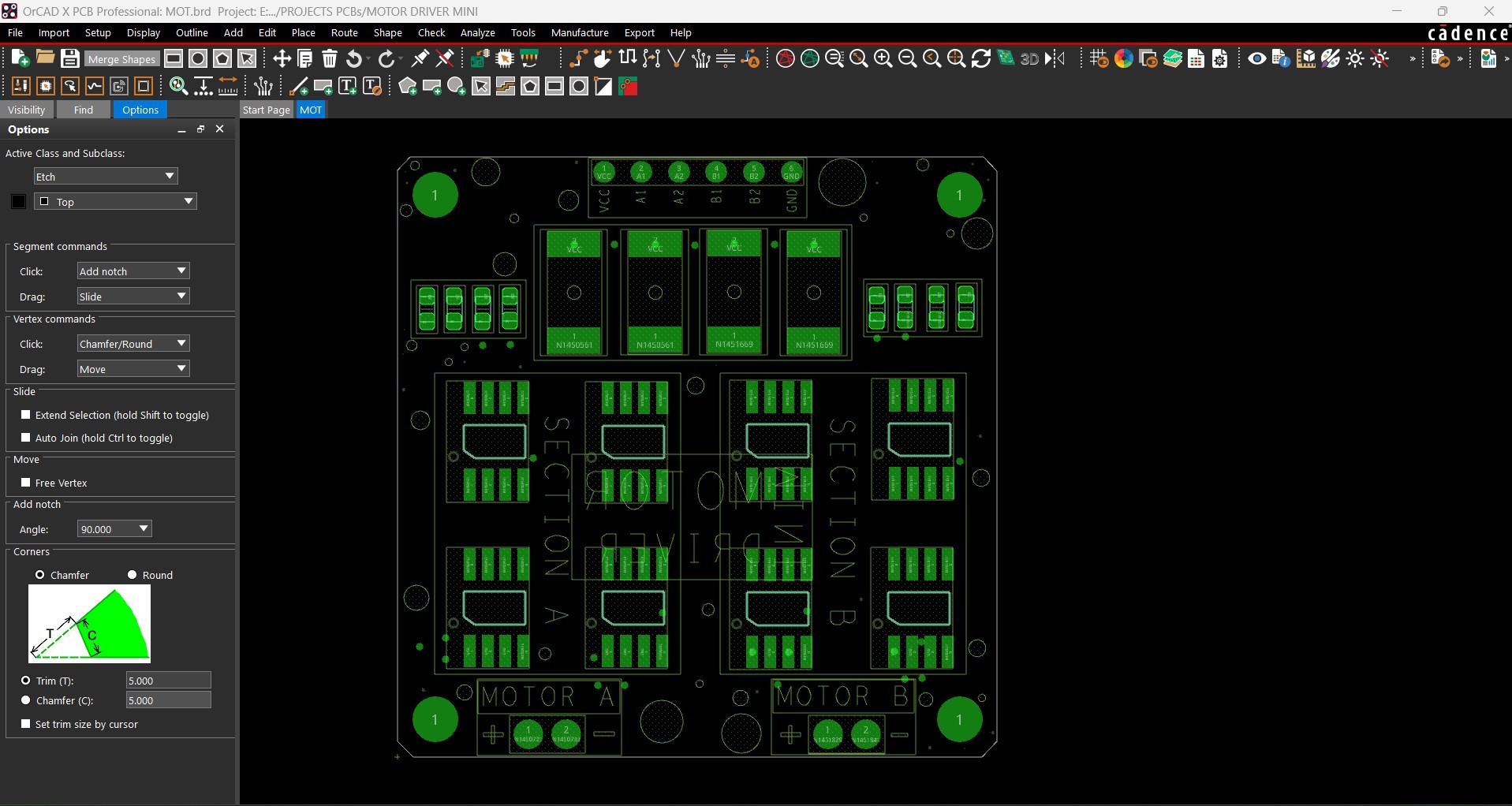
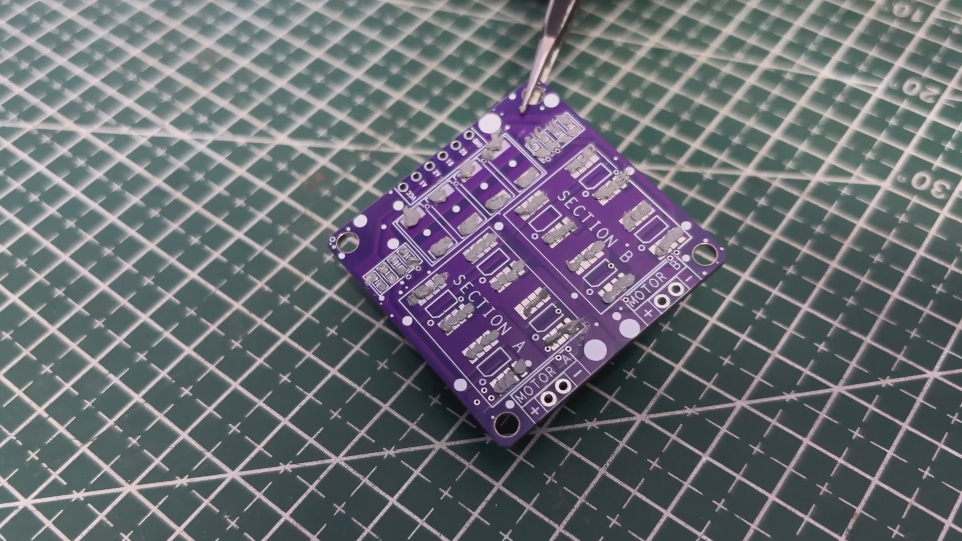
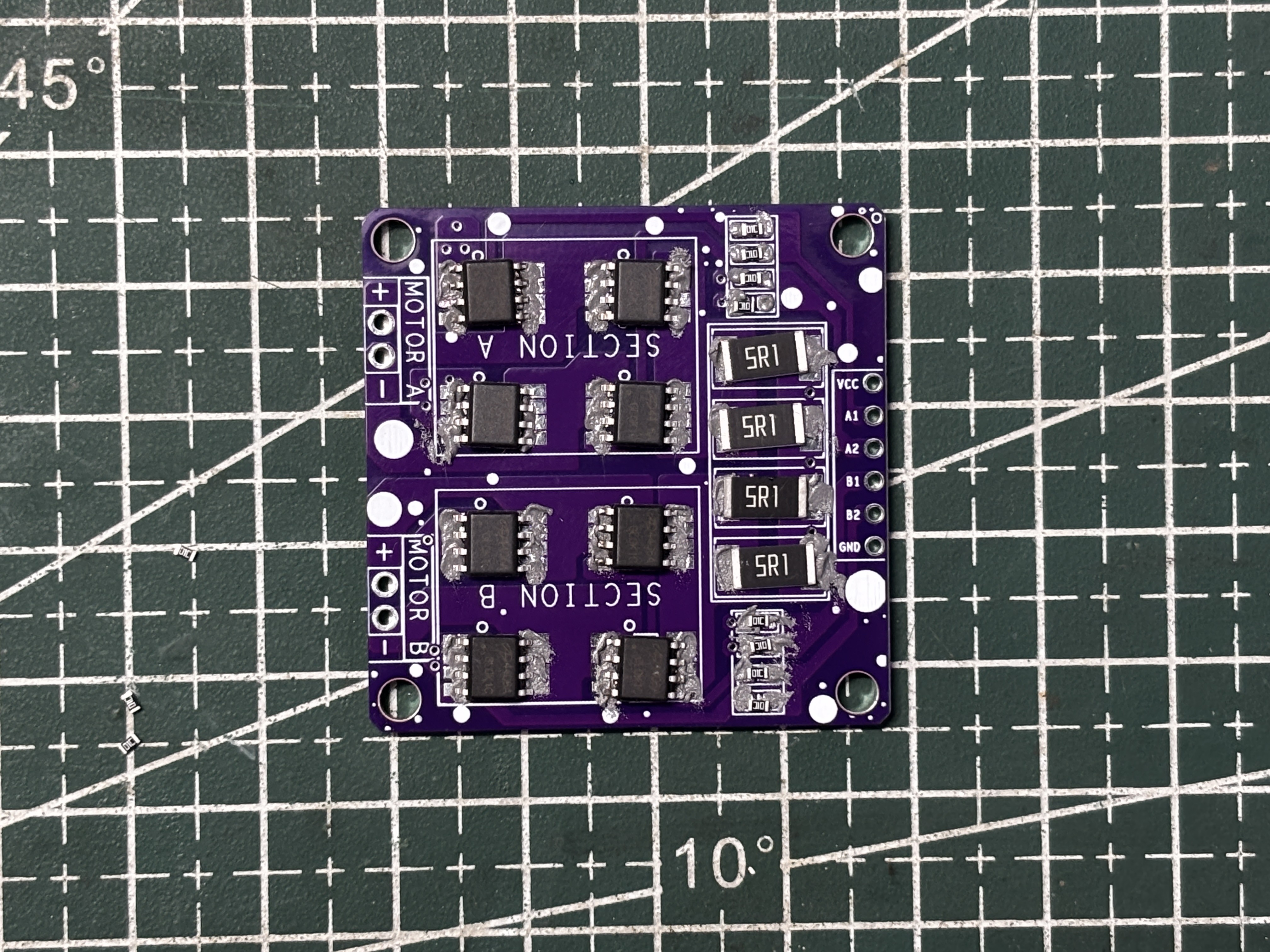
The PCB design for this project was pretty straightforward. Once the schematic was ready, I exported the netlist into my PCB editor and started by creating a simple square outline for the board. From there, I began arranging all the SMD components inside that space, starting with the H-bridge MOSFETs for Motor 1 and Motor 2, placing them in the correct layout.
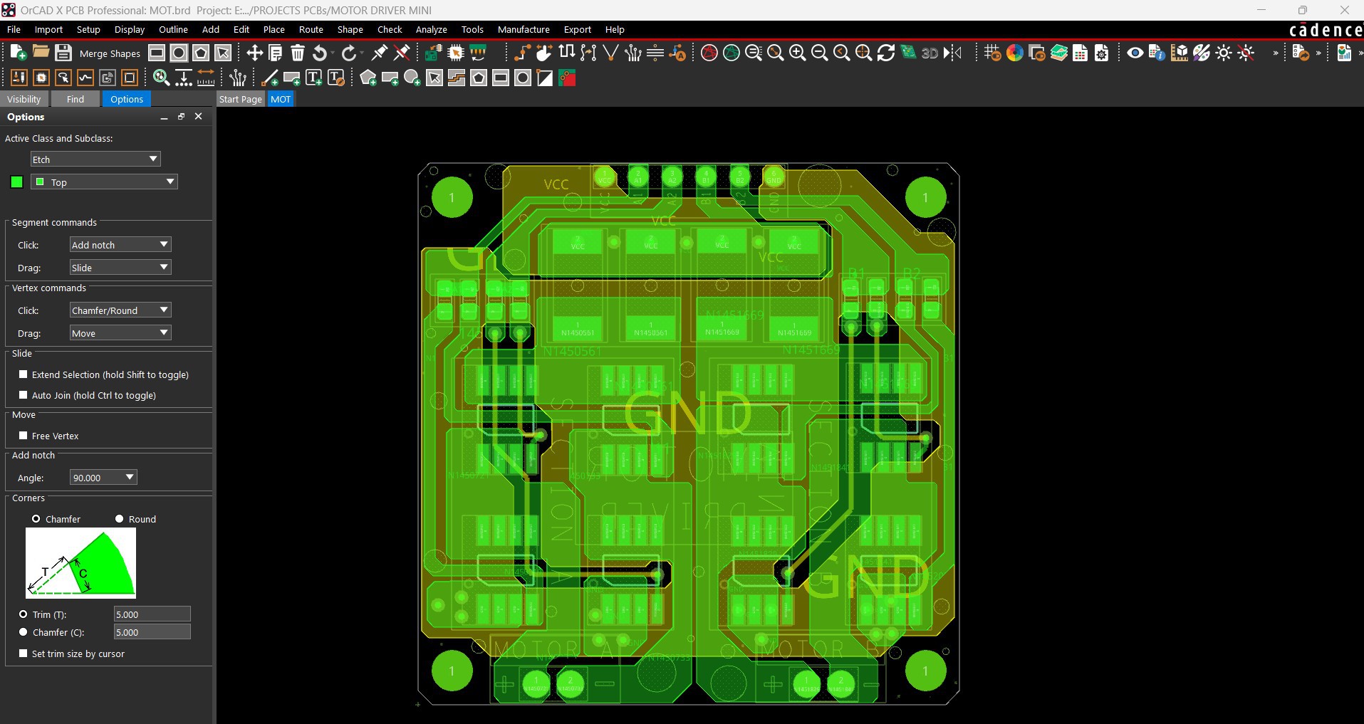
The resistors linked to the MOSFETs for Motor 1 were placed right next to that set, and the same for the resistors for Motor 2. The load resistors, which use a 2512 package, were placed on the top side above the MOSFETs. After that, I routed all the traces, making sure to keep the VCC and GND lines thick, along with the traces leading to both motor connectors—just to handle current properly.
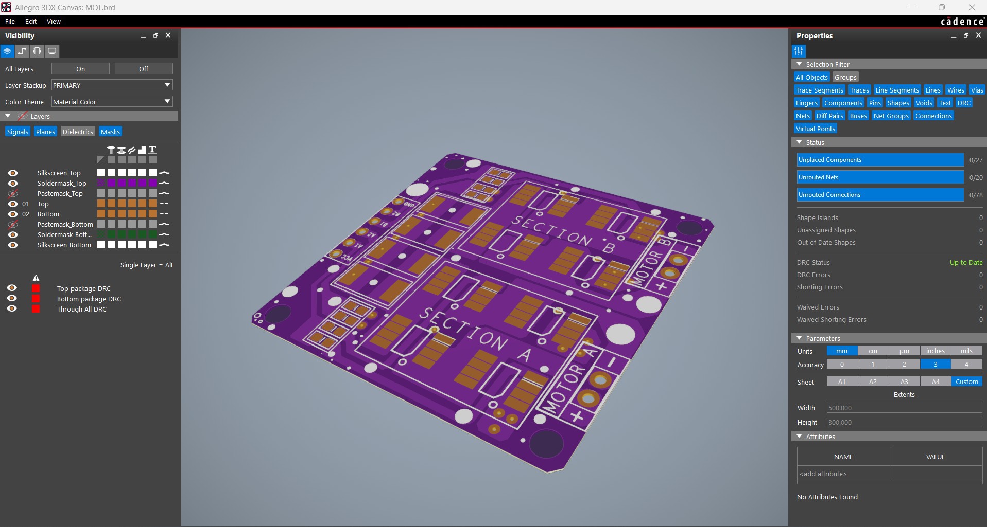
Once the layout was finalized, I added a few aesthetic touches too, like small dots, outlines around components, and other simple details on the top silkscreen to make the board look a bit nicer.
JLCCNC SERVICE
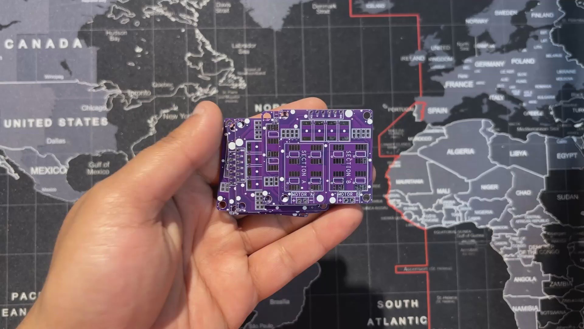


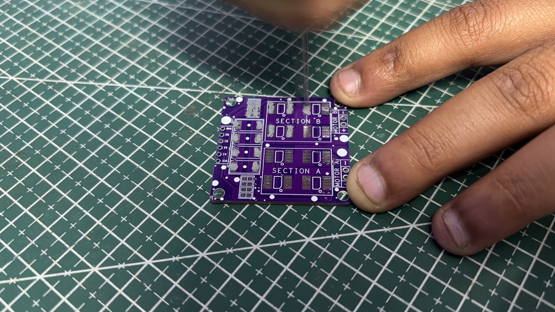
Once the board design was finalized, I chose a purple solder mask with a white silkscreen and uploaded the Gerber files to JLCPCB’s quote page. I usually stick to white or black for most builds, but this time I wanted to switch things up—and the purple option looked too good to skip.
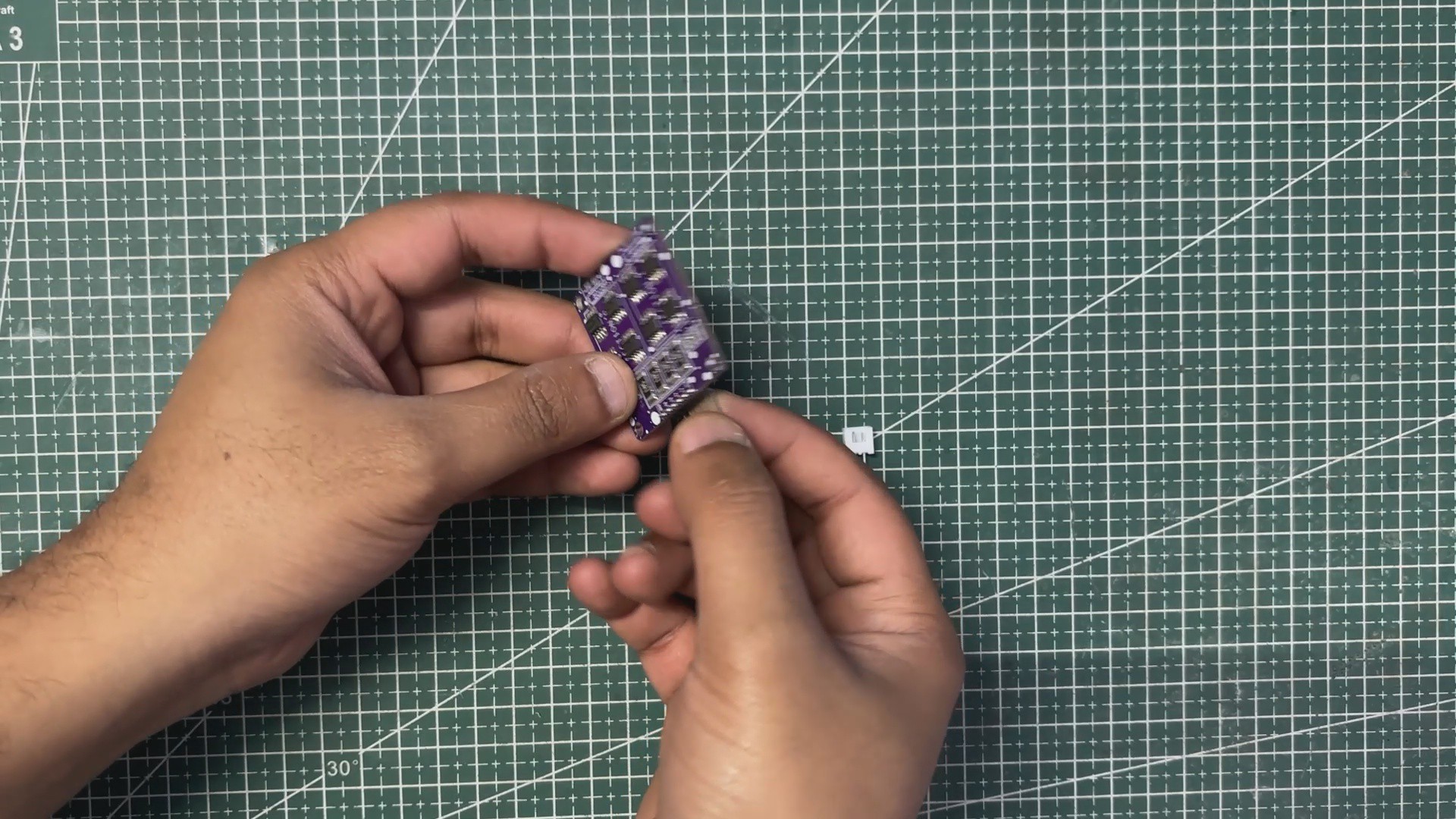
I’ve tried PCB services from different manufacturers over the years, and this time the boards arrived in under a week with a clean finish and sharp silkscreen. Everything aligned perfectly with the design, and the purple solder mask really made the PCB stand out.
Although this project didn’t require any CNC-machined parts, the overall build was supported by JLCCNC, who specialize in CNC machining, milling, and custom mechanical fabrication. Their platform lets you upload STEP files, choose...
Read more »


 YSPACE Labs
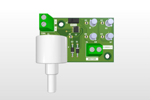
 Arshmah Shahkar
 Andrew Kowalczyk