For the solar cell, I bought this one, optimized for indoor use. The datasheet says max power is 714 mW. Of course, this is in full sun light with 100,000 lux. I tested it in my living room with not very bright artificial light for worst-case condition (my lux meter shows 200 lux). With this I can get get about 5 mW out of it.
The interesting thing about solar cells is that they have a max power point. If you use a lower resistor as a load, the current increases, but the output power measured in watt gets lower below some resistor value. But if you increase the resistor too much, the output power gets lower again. There is a sweet spot for the maximum output power. For determining it I used my decade resistor box:
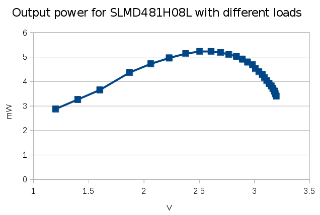
Together with my multimeter, I tested it for different loads and noted the measured values in a spreadsheet (see here in Libre Office format). This is the result:

As you can see, the maximum power is at about 2.6 V, with about 5 mW output power. I tested it for a brighter light, about 700 lux, and the maximum output power point was at the same voltage. Output power for this light is 6.2 mW. I used a LED flashlight for it, and looks like the solar cell couldn't use the wavelength of it as good, I would have expected more.
I found a nice chip, which is designed to be used with solar cells and other such renewable energy source, the LTC3106 ( https://www.digikey.de/short/3nzcm2 ). With this chip it is possible to configure the voltage at to get the max power from the attached solar cell. This is called maximum power point tracking, MPPT, see here for details. It can also charge an attached battery or storage capacitor and use this automatically, when the light goes off. The efficiency is about 90% at 2.6V input voltage. If we assume even worse lights, e.g. 100 lux, we might have 1 mW available power, at a regulated output voltage of 3.3 V.
I plan to use a bigger display than the 2.7" display of my first test, this 4.2" ePaper display. The ESP8266 doesn't have enough memory to buffer a frame, so I bought an ESP32 for it. I can already compile NodeMCU from source for it from the dev branch of the github repository and it runs. With WiFi activated it needs about 110 mA at 3.3 V. In deep-sleep mode I measured about 5 μA. The LTC3106 needs 2 μA quiescent current.
Let's say worst case would be 10 seconds to start the module, connect to WiFi, download a new image and update the ePaper. The ePaper needs about 8 mA max current (of course, only when updating, it doesn't need any power for displaying content), so this would be 118 mA total, which means 390 mW. If we have always light, it would therefore be possible to use a duty cycle of 1:390. This means 3900 seconds off and 10 seconds on, which means we can update he display once per hour. When in deep sleep mode, together with the voltage regulator, the circuit needs less than 10 μA, which is 0.033 mW and can be ignored for the calculation, because the solar cell provides more than 1 mW.
The ESP32 could measure the output voltage of the solar cell, so that the display doesn't get updated at night, but the battery or super capacitor can be charged, for maybe even shorter update rates. Or the update rate can be adjusted, depending on the charge state of the storage capacitor. But the conclusion is, that the project is feasible.
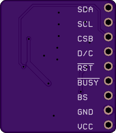
Now I'm waiting for the breakout board to test the new ePaper, already ordered at OSH Park:


 Frank Buss
Discussions
Become a Hackaday.io Member
Create an account to leave a comment. Already have an account? Log In.