I got the breakout board for the new 4.2" black/white/red ePaper display, thanks to @jarek319 for the initial Eagle circuit and initial layout. I did the layout again, using all 0805 components. If you want to build your own, this is board from @oshpark and this is the Digikey cart to populate 2 boards, and including one display.
The firmware for the new ESP32 is in the github repository of the ePaper project. It is based on the http_request example project and the Arduino script from this project, ported to the ESP32 framework. Some sample images are also there, together with the convert.py script to convert your own PNG files to the BIN file format used by the firmware. To compile the project, you need to install the IDF framework and toolchain first, as described here. After starting, the firmware loads image.bin from a webserver, then goes to deep sleep mode and waits for a reset.
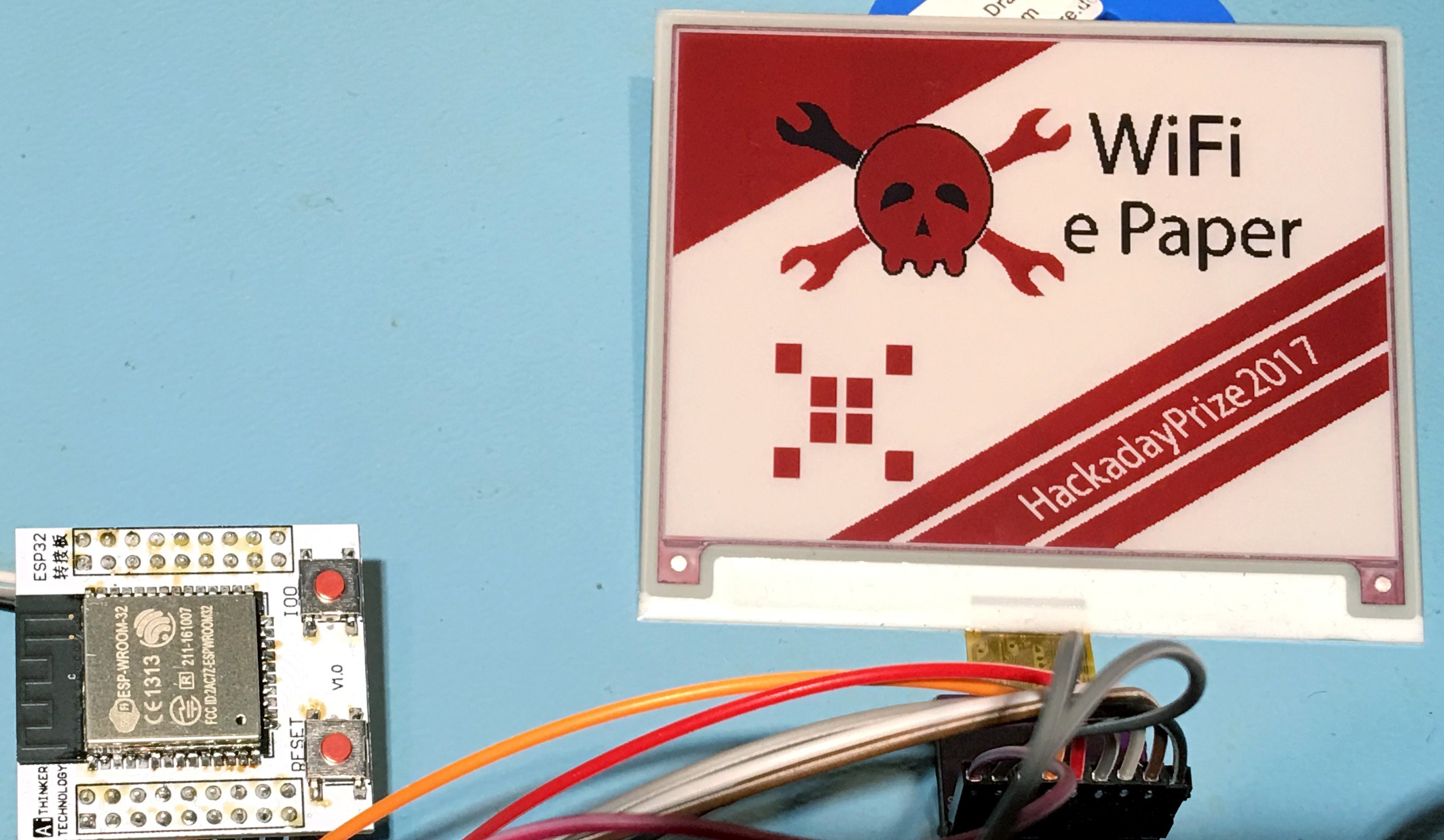
This is how it looks like:
The new firmware doesn't use the NodeMCU project for using Lua with the WiFi module anymore. There is a development branch of the NodeMCU project for the ESP32, but still many libraries missing and not much RAM left. Even after reducing RX and TX buffer etc., I get a out of memory error if I try to allocate a 50 kB string or more in Lua. The reason might be that the new IDF framework needs more memory than the old for the ESP8266, and Lua needs memory, too, even when only loading the libraries, because they are not in flash, but loaded to RAM. And probably because of the reduced RX and TX buffers, I got timeout messages and canceled transfers for larger files (the 30 kB binary image files). The Hello World IDF example app, I could allocate up to 280 kB and with the new firmware, using just C and the IDF library, the image is loaded always, without timeouts.
High resolution photo of the test setup:

 Frank Buss
Discussions
Become a Hackaday.io Member
Create an account to leave a comment. Already have an account? Log In.
Do you have a close-up photo that shows of the wiring? I've got the parts and the breakout board and am going to try to replicate this setup. thanks, drew
Are you sure? yes | no
Sorry, I have already disassembled it, because I'll connect the display with the new test board next, when I have some time. But you can find the wiring here:
https://github.com/FrankBuss/wifi-epaper/blob/master/firmware/main/epd.c#L15
The correspondent GPIO numbers on the ESP32 wroom board:
http://www.pighixxx.com/test/2016/08/wroom32/
and then +3.3V and GND, and I think I connected the BS pin to GND.
Note: If you use the cheap wroom board, you need to activate the ROM serial bootloader, when you update the firmware:
https://github.com/espressif/esptool/wiki/ESP32-Boot-Mode-Selection
Are you sure? yes | no
Thanks for the links
Are you sure? yes | no
Awesome! Well done!
Are you sure? yes | no