-
1Join the Upper and Lower Rotor Assemblies
- Attach the upper rotor plate to the lower rotor assembly
- Using 12 screws attach the lower rotor plate to the servo mounts and pillow blocks
-
2Add the Electronics to the Rotor
- Place the Power Distribution Board onto one of the Board Holders
- Place the ESP32 Dev Board onto the second Board Holder
-
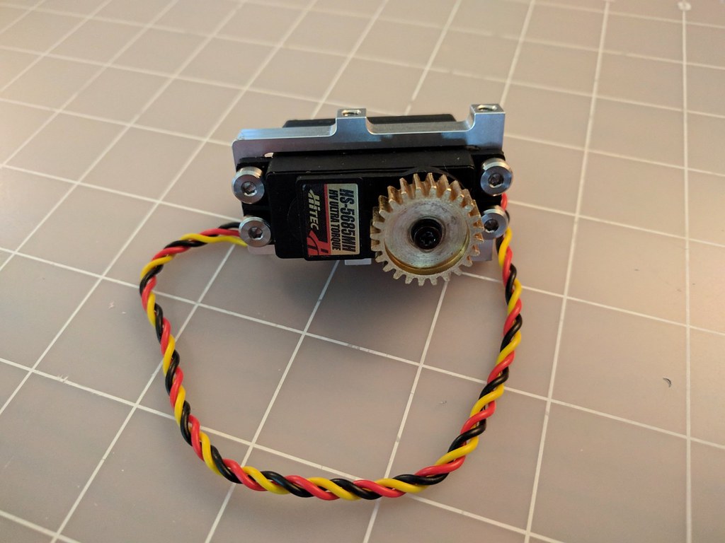
3Build the Servo Assemblies
Parts Required: Standard Size Servo, Servo Mount, Shoulder Bolt Screws, Servo Gear, Servo Shaft Screw
Tools Required: 3/32 Hex Key, Screwdriver, Thread Locker
![]()
- Place the servo in the mount with the servo shaft between the side tapped holes
- Apply a medium strength thread locker ( Such as Loctite Blue 242) to the threads of four of the shoulder screws and secure the servo to the mount
- On the servo shaft screw apply thread locker, using a Philips screwdriver attach the servo gear to the servo shaft
![]()
-
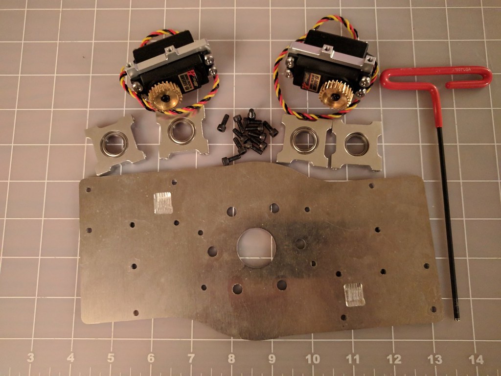
4Create the Lower Rotor Assembly
Parts Required: Two Servo Assemblies, four Pillow Blocks, 12 socket head screws
Tools Required: 7/64 Hex Key
![]()
- Using two screws each, attach the servo assemblies
- Using two screws each, attach the four pillow blocks
![]()
-
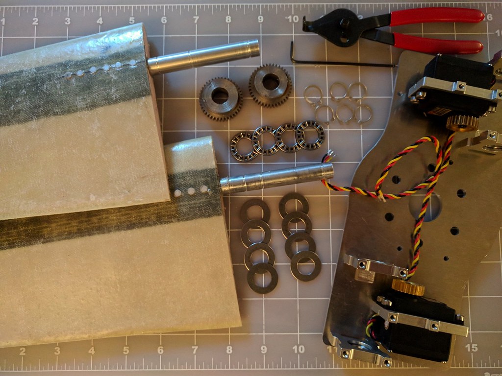
5Attach the Rotor Blades to the Lower Assembly
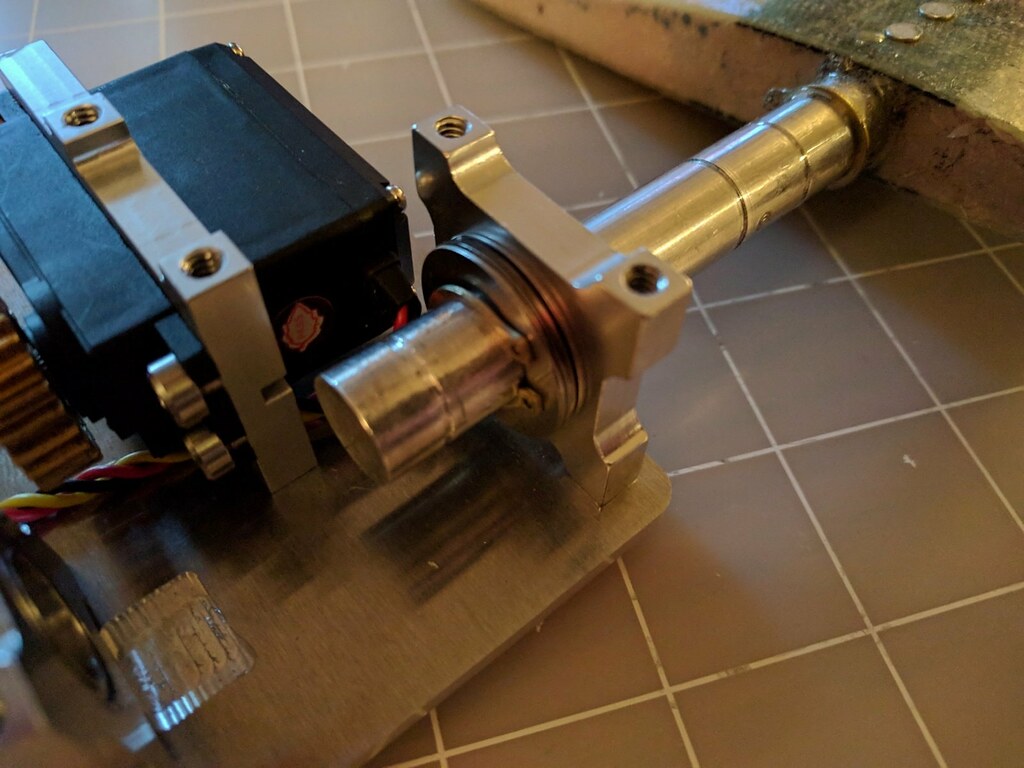
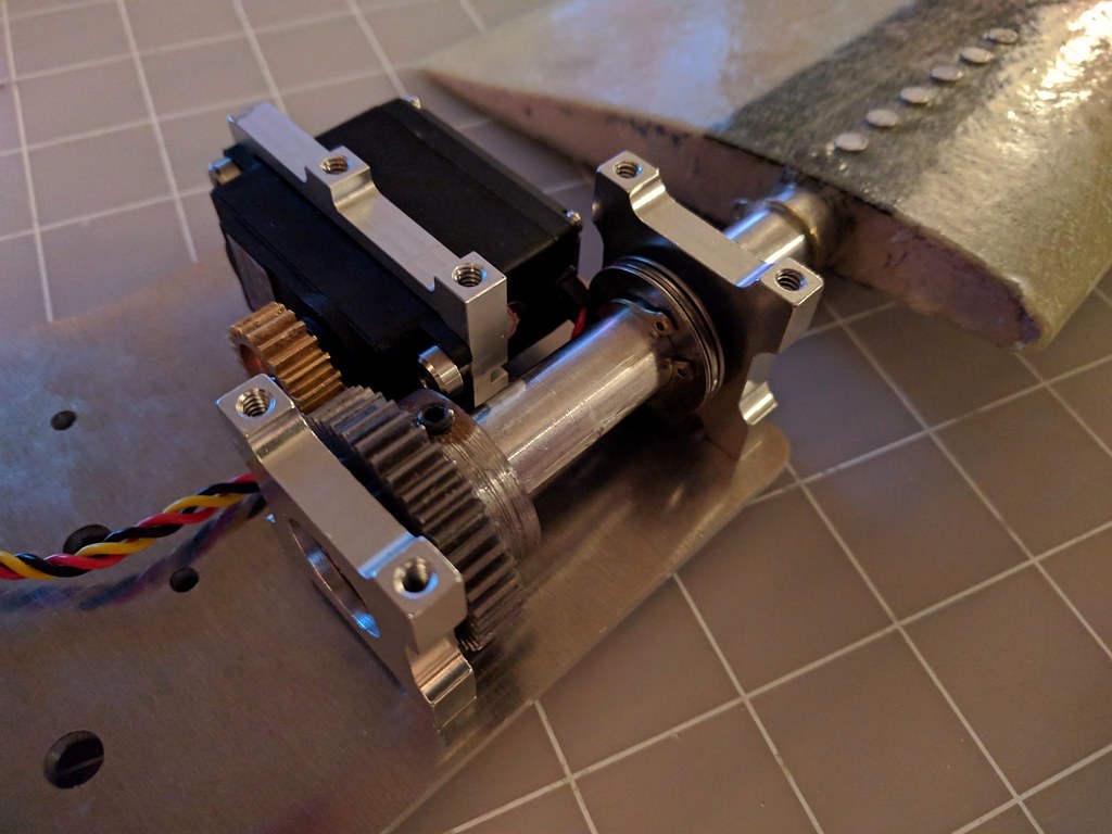
Parts Required: Lower rotor assembly, two rotor blades, two axle gears, four thrust bearings, 4 thrust washers, six retaining rings
Tools Required: Snap Ring Pliers, 5/64 Hex Key
![]()
Place the outer most retaining ring on the axle
![]()
Feed the axle about 1/2" through the outermost pillow block. Add a washer, a thrust bearing, a second washer and then a retaining ring.
![]()
Feed the axle closer to the innermost pillow block and add the axle gear
![]()
Feed the axle through the innermost pillow block. Add a washer, a thrust bearing, a second washer and a retaining ring.
![]()
Repeat for the second rotor blade
-
6Create the Upper Rotor Assembly
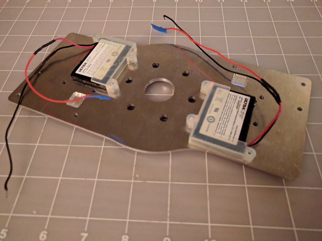
Parts Required: Upper Rotor Plate, two batteries, two battery holders, six socket head screws
Tools Required: 7/64 Hex Key
![]()
- Using three screws each, attach the the battery holders to the upper rotor plate
- Place the batteries inside the battery holders
![]()
-
7Prep/Design Work
Rotors/propellers are designed for specific applications. The airfoils and blades need to be designed to work with the chosen engine/motor. One the rotor blades are defined, the required torque to actuate the blades can determined and the appropriate servos selected.
The following instructions up until the rotor assembly can be done in any order. However, they are listed with the longer lead time items first for a more efficient build process.
-
8Build the Rotor Blades
In addition the the following instructions, the rotor build process is also documented in a video.
- Cut the rotor core
- Layup the fiberglass around the core
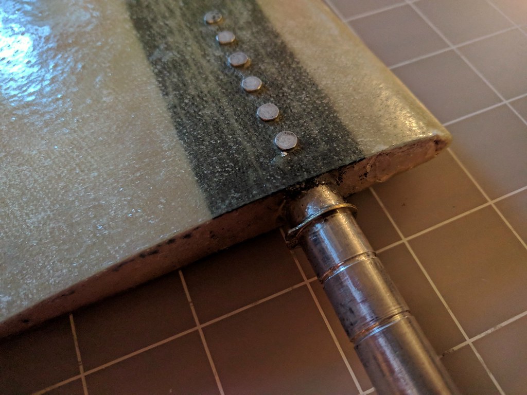
- Machine the axle
- Epoxy the axle into the rotor
- Rivet the axle in place
-
9Print the Battery and Board Holders
-
10Cut the Rotor Plates
The rotor plates were designed to be cut on a CNC router. The CAD for the plates can be found in the repository.
EVPR: Electric Variable Pitch Rotor
An electrically actuated variable pitch rotor with a wireless interface
 Peter McCloud



Discussions
Become a Hackaday.io Member
Create an account to leave a comment. Already have an account? Log In.