 Peter McCloud
-
Prototype not working in time for the Hackaday Prize Deadline
10/21/2017 at 00:56 • 0 commentsLast week, the first test of the EVPR prototype working in concert with the flight controller was conducted. It was found while the previous servos had sufficient torque, but that the internal servo gears were not suitable for the vibration and shock environments. New servos with steel gears were Additionally the retaining rings needed to be upgraded to heavy-duty versions.
On Tuesday the new rings arrived and the axles were modified for them. Yesterday, the new servos arrived. The new brushless servos are really cool. The are super quick and have none of the singing that the brushed servos had. Late last night the new servos were installed and testing began last night and continued into today.
Unfortunately this afternoon, the blades on the prototype came loose. On startup the engine revved up quickly to a high RPM and the rivets holding the blades in placed sheared, sending the blades flying.

Axle with sheared rivets Unfortunately there's only 14 hrs left until the deadline for the Hackaday Prize and there isn't a working prototype to meet the contest requirements. The prototype IS close to working. Stay tuned!
-
First Active EVPR Tests
10/14/2017 at 17:36 • 0 commentsAfter completing the flight controller setup, it was time to test the rotor with the Pixhawk actively controlling the rotor surfaces. The rotor was activated, check-out and then the gas engine was turned on. Everything appeared to work well, but when the engine was turned off, it was found that one of the rotor blades had partially slipped out of place.
![]()
Fortunately, there was an extra groove in the axle shaft that caught the retaining ring when it slipped out, keeping the rotor blade from flying out. The grooves were found to be a little shallow, so they were machined slightly deeper. Additionally the retaining rings did seem to close as tight as they should, so new retaining rings were used. There was also some stripped internal servo gears, so the servo was replaced as well. At the time I was thinking that the blade slipping might have jammed the axle gear in place and that caused the gears to stripped.
A second test was conducted and the other rotor blade popped partially out and the brand new servo on the side that stayed in place had stripped internal gears. So it doesn't seem to be the rotor blade failures that are causing the stripped gears, but the normal environments.
![]()
The rotor blades popping out, should be relatively easy to the fix. There are heavy duty retaining rings that have a higher holding force and I've already ordered those. The servos required a bit more thinking. The gears for the current servos are listed as "Metal", but they are made from aluminum and brass. It's obvious that either steel or titanium gears would be a better choice. However, servos with steel gears have higher torque, which isn't a bad thing, but draw more power.
The solution is to use brushless servos. The servos I selected are the Hitec 9475SH. It's got steel gears, 50% more torque, is almost twice as fast and draws 900 mA at stall torque vs. 2700 mA that the current servos require, which should push the battery life almost up to 30 mins. The downside of course is money. The new servos cost $99 instead of $40.
I thought that this failure was going to mean that I wouldn't have a working prototype in time for the Hackaday Prize deadline. However, the retaining rings will get here on the 17th and the servos will get here on the 19th. I should have the new retaining rings installed by the time the servos show up, and it should only take 20 mins to install the new servos. That'll give me about 36 hrs to test and update my video showing the working prototype.
-
Pixhawk driver and EVPR Firmware working!
10/06/2017 at 01:26 • 0 commentsInitial testing of the Pixhawk drivers and the EVPR Firmware was a success as shown in the video below. Next step is re-configuring the control mixer and setting the correct servo ranges for the rotor blades.
-
Initial EVPR code working, PX4 driver completed
10/02/2017 at 05:03 • 0 commentsThe initial code for both the EVPR master and slave nodes is FINALLY ready. Additionally the PX4 driver which passes the servo settings to the EVPR master node is also complete. The servo values are correctly being passed from the flight controller tothe master node via UART and the values are being successfully passed from the master node to a slave node via UDP packets.
The code can be found in the repository at the following locations:
EVPR Master Node
https://github.com/mccloudaero/evpr/tree/master/electronics/firmware_evpr_master
EVPR Slave Node
https://github.com/mccloudaero/evpr/tree/master/electronics/firmware_evpr_slave
PX4 Driver
https://github.com/mccloudaero/evpr/tree/master/electronics/px4_uart_driver
Now the electronics will be attached to the vehicle and more testing of the code can be conducted. If the servo values with the engine off are successfully received, then the testing can proceed to turning the engine and checking out the code on the running vehicle.
-
Firmware Progress
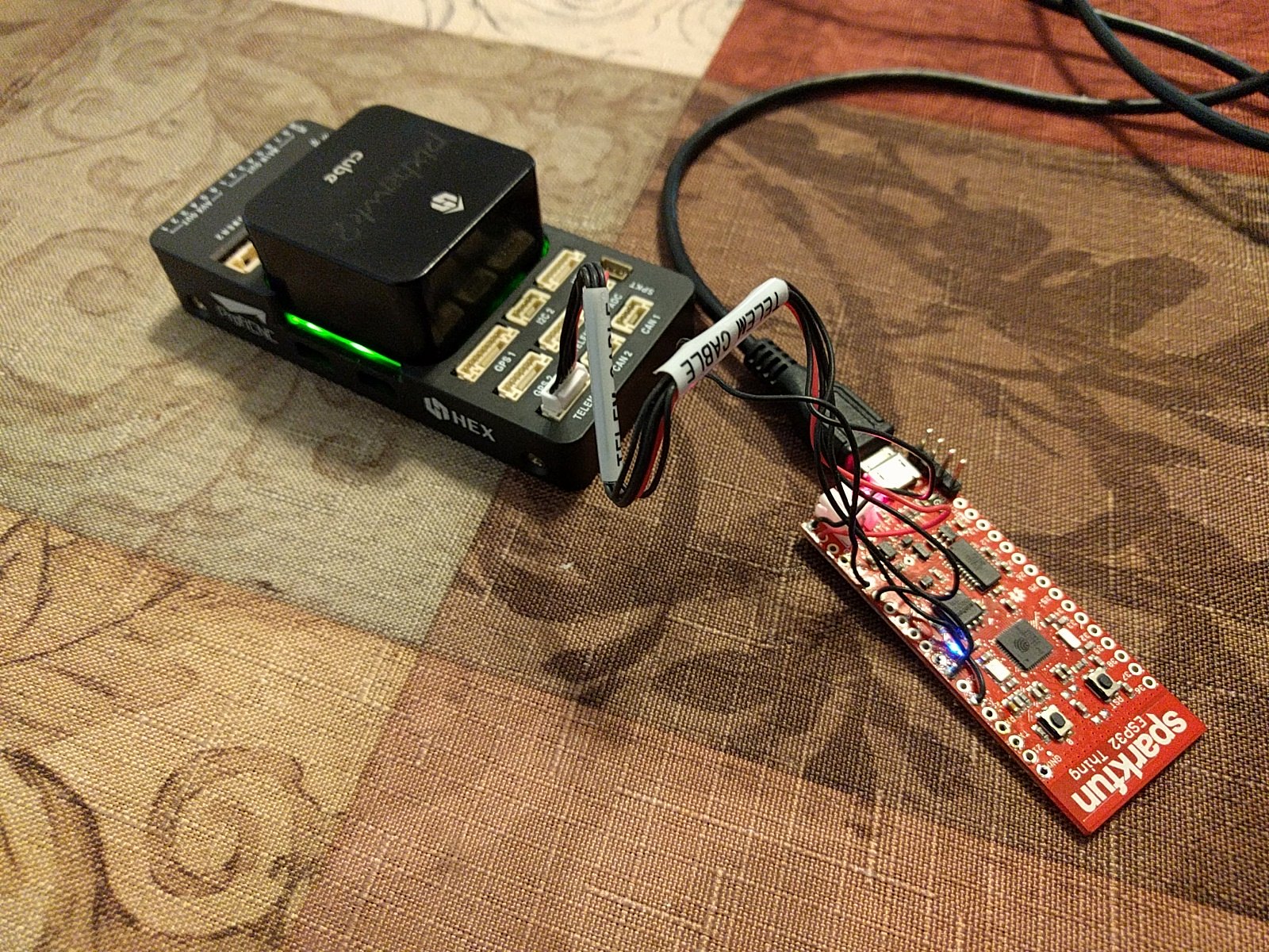
09/21/2017 at 03:47 • 0 commentsSolid progress is being made on the firmware, particularly for the master node that connects to the flight controller. As the firmware is being developed, it's tested periodically on an ESP32 connected to the Pixhawk 2.1 (shown below).
![]() ESP32 is connected via on of the UARTS to the TELEM2 port on the Pixhawk. The Pixhawk sends out messages via the mavlink format on the TELEM2 port. The data is then parsed using the mavlink c libraries. The firmware is finally correctly parsing the mavlink messages, so the next step is the pass the relevant messages onto the other rotors.
ESP32 is connected via on of the UARTS to the TELEM2 port on the Pixhawk. The Pixhawk sends out messages via the mavlink format on the TELEM2 port. The data is then parsed using the mavlink c libraries. The firmware is finally correctly parsing the mavlink messages, so the next step is the pass the relevant messages onto the other rotors.The ESP32 is also running a webserver via Mongoose to provide a status page. Example shown below:
EVPR MASTER NODE STATUS
Time since start: 28.942919 secs
Connected stations: 1
Station 0 MAC: AC:7B:A1:DE:DB:4F
Connected to Flight Controller
System ID: 1
Most of the major pieces for the firmware are in place, it's just a matter of tying together all the pieces now. Once it's done, then the next step will be to test a single EVPR on the vehicle and test the ability to change pitch.
-
Building Progress, Working on Firmware
09/04/2017 at 18:57 • 0 commentsOver the last few weeks, the hardware for three more rotors has begun to take shape. Below are some of the parts coming together.
![]()
Clockwise from upper left are three clockwise blades (one completed, two almost complete), the cores for all of the counter-clockwise blades, rotor plates for three more rotors, including one with servo mounted, and the latest power module.
The goal is to have a second clockwise rotor ready for testing by the end of the week. The other rotors will be completed in the next few weeks.
The power module has been revised and a diagram was made to show the wiring.
![]()
Progress is moving forward on the firmware as well. The data transfer from the master node to the slave nodes (rotors) is working using UDP. Work is now focused on transferring the data from the flight controller to the master node. The initial concept was to use I2C, but it appears that the code for the ESP32 to act as a slave I2C device hasn't been implemented. CAN was my next choice, but the ESP-IDF doesn't have a driver. There is another Hackaday project #ESP32 CAN Driver that looks promising, but between that and having to write a custom driver for the PX4 Firmware, it's proably too much work for the time left. The Pixhawk2 has a wierd note about SPI not being recommended, so that was out.
So that leaves using UART for now. This should be relatively straight forward since 1) There's already a PX4 driver for sending PWM signals through the UART port and 2) The UART is fully implemented in the ESP-IDF and there are examples available. In the long term I hope to have multiple protocols to give the user multiple options.
So if all goes well, the firmware should come together in the next two weeks and then the control scheme with the Pixhawk in the loop can start being tested!
-
Still holding together, getting ready to make more rotors
08/20/2017 at 22:49 • 0 commentsUpdated design
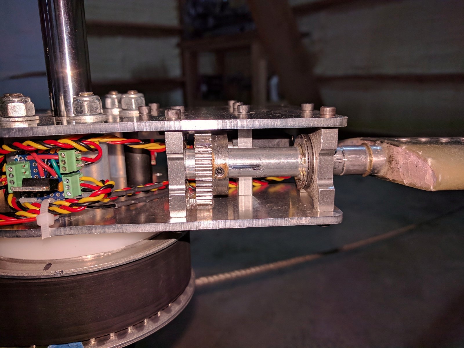
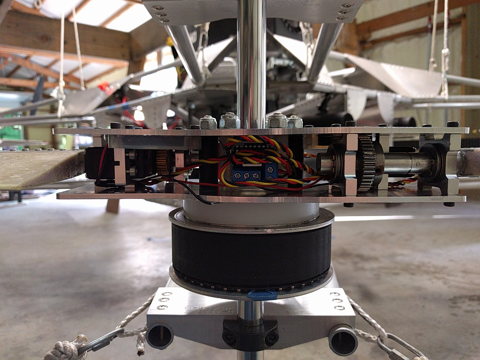
After the first successful (success == not flying apart) rotor test last week, the design was tweaked to change the orientation of the servos so that the centrifugal force held the internal gears in place instead of tearing them out. The change required moving the axle gear, and a new set of hub plates were cut with the gear pockets moved. Below is a shot of the reassembled hub with the reversed servo orientation.
![]()
Rotor weight
The rebuild of the rotor allowed the opportunity to weigh the EVPR by itself (versus attached to the hub). The complete assembly weighs 2.7 lbs (note: in the future I still need to add the alternator, but the batteries give about 10 mins of run time right now). The fixed pitch rotors weighed 1.25 lbs, so adding variable pitch only adds. 1.45 lbs, better than I'd anticipated (The 7075 aluminum axles reduced the weight considerably). For a full set of 4 rotors the total increase in weight will only be 5.8 lbs.
In contrast, the grid fins control concept is anticipated to weigh 6 lbs a piece (not including actuators and mounting hardware. A set of 4 would add 24 lbs of weight. If the variable pitch rotors perform as hoped, that will mean upwards to 18 lbs of weight savings.
More Testing
With the rotor rebuilt, two more tests were conducted. Both tests were 60 seconds long and the rotor held together. Both blades have survived 3 start-up/shut-down cycles and 3 minutes of run time. It's looking like the mechanical bugs have mostly been worked out.
More Rotors
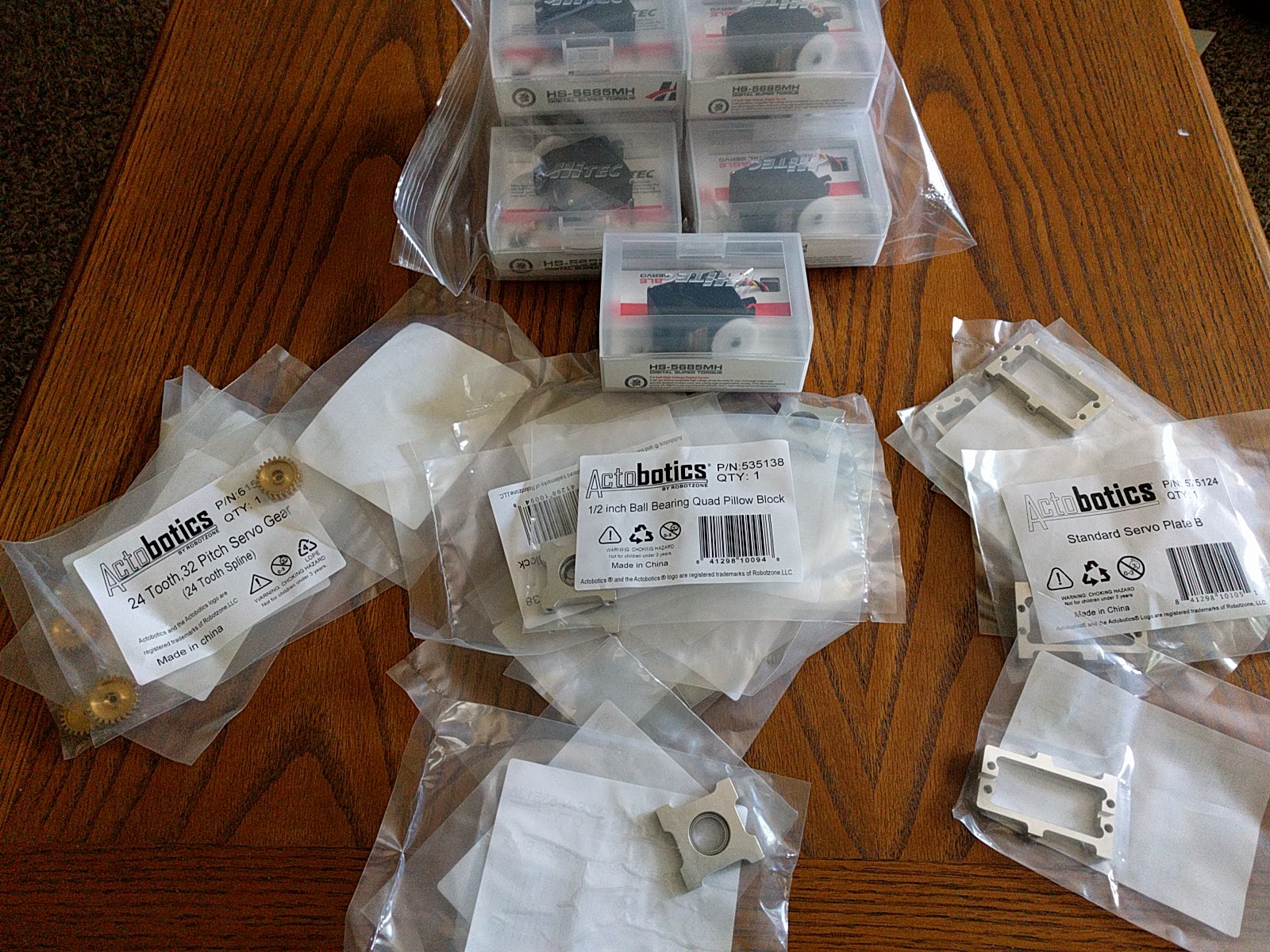
With the hardware performing well, the prize money from the Wings, Wheels and Walkers round was invested in buying enough parts to build a full set of variable pitch rotors. The majority of the hardware is from Servocity.com and the parts arrived on Friday.
![]()
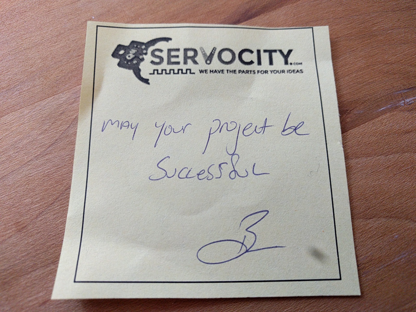
I've been really happy with their hardware so far and if you send them pictures of your project, you can get a discount. It's also pretty cool to get a handwritten note with your order!
![]()
Forward Work
More testing needs to be done on the first rotor to build up the time and cycles on the hardware to make sure things will hold up in the long term. The other big priority is to to mature the firmware and demonstrate controlling the servos.
As time allows, the buildup of the second rotor will continue. The hub plates have already been cut and the rotor blades are almost complete. Work on the build instructions have started now that the hardware has reached a somewhat stable state.
-
Design Iterations
08/12/2017 at 17:21 • 0 commentsSince the last project log, the design has undergone a few iterations. The main problem had been keeping the rotor blades attached to the hub. One failure mode was that the blade came detached from the axle and the second was that the axle detached from the hub.
![]()
The axle was fixed by added a second retaining ring so that both pillow blocks keep the axle from flying out. It also became apparent that the pillow block bearings were not adequate to take the axially loads. A thrust bearing was added at each pillow block to improve the design.
![]()
![]()
Better bonding techniques were used to attach the blades to the axles. Another test was conducted (see the video later in the log) and for the first time everything survived past the engine starting up. Then after running for about 90 seconds the blades detached from the axles.
It was decided that only using epoxy to keep the blades attached wasn't going to work and that rivets should be added. However the 1045 carbon steel axles are difficult to machine (at least with the equipment I have) due to their hardness. After some research it was decided to switch the steel axles out for 7075 aluminum which has nearly the same tensile strength, but is easier to machine and much lighter.
![]()
The latest iteration of the axle is shown above. A knurled surface was added to further improve the adhesive bonding to the axle. After the axle was placed into the blade, holes were drilled though the assembly and six solid aluminum rivets were added.
![]()
The new axles and rivets did the trick. For the first time the whole assembly survived startup, running for about 60 seconds and engine shutdown.
A few other issues have popped up as well. The screws holding the servo in place allowed some movement of the servo which wasn't desired. Torquing the screws down further wasn't an option with the plastic flanges. The solution was to use precision shoulder screws to mount the servos.
![]()
The screws are shown in the image above next to the red and black wires. They work great, but at $2.24 a piece they are pricey.
Losing rotor blades caused vibrations that damaged the quadcopter frame. Three of the gussets on the rotor arm were cracked. Below is a shot of one of the worst cracks.
![]()
Part of the problem was the concave corner that I had cut too sharply. The gussets were replaced, but a large radius was added to the corner to prevent a crack from starting.
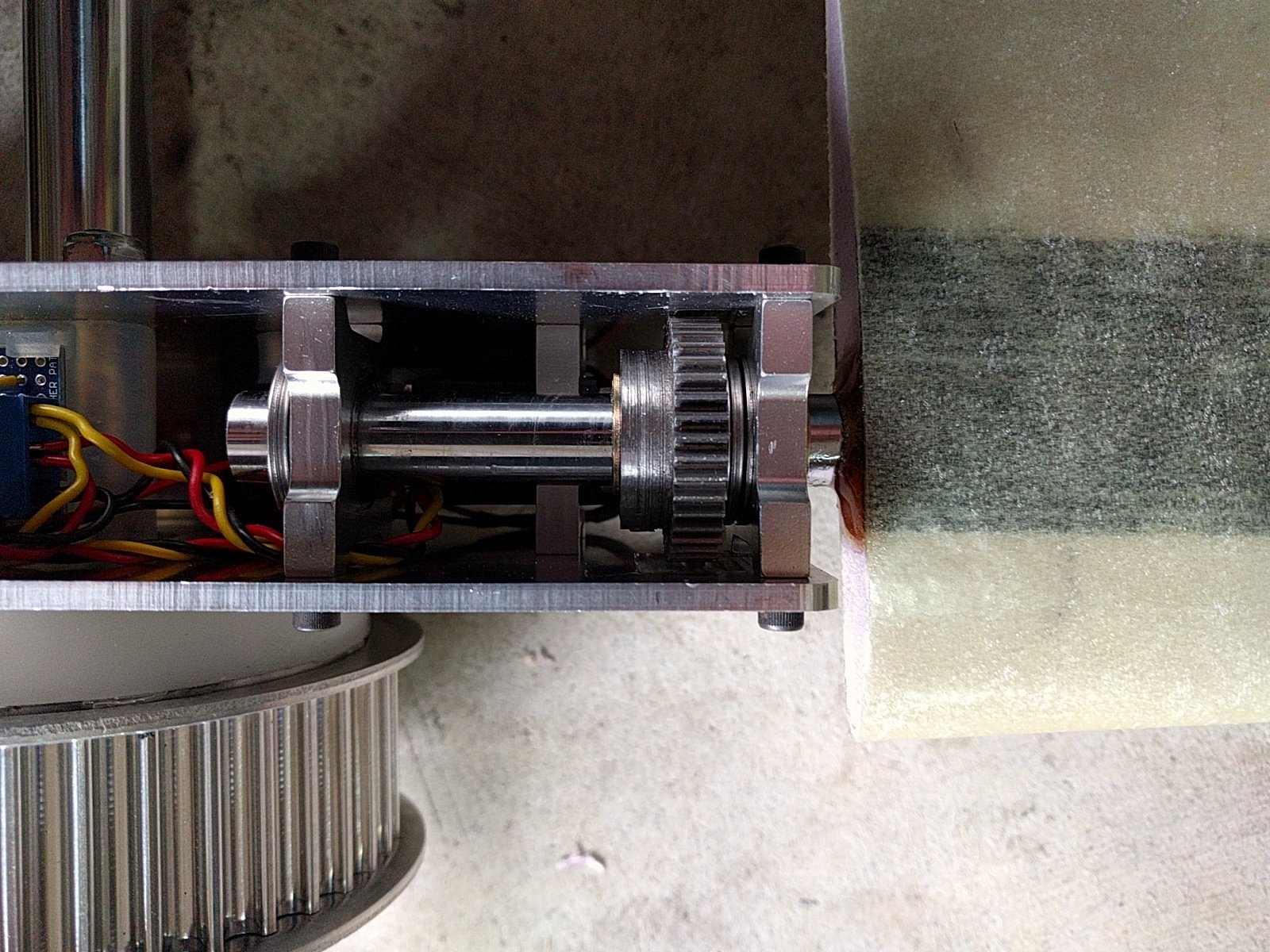
I'd love to say that the hardware design is complete, but one last issue popped up during the last test. Inspecting the hardware after the test, one of the servo was not holding position and would make strange noises when the blade was rotated out of position. Taking about the servo it was found that one of the gears which just has a friction fit had come loose.
![]()
The culprit gear is the brass gear in the middle of the assembly above. Why did it come loose? While the gear case holds the gear in place from top, the centrifugal forces are likely pulling the gear out of the friction fit. To keep this from happening the servo should have the top pointing inwards instead of outwards so that the centrifugal force helps the gears stay in place instead of pulling them apart.
Looking at the design it should be straight forward to make the changes. It'll have the added benefit off keeping the main servo gear attached to the spline as well. The only downside will that it will more difficult to adjust the blade pitch with the gears inside of the hub, but it'll still be doable.
-
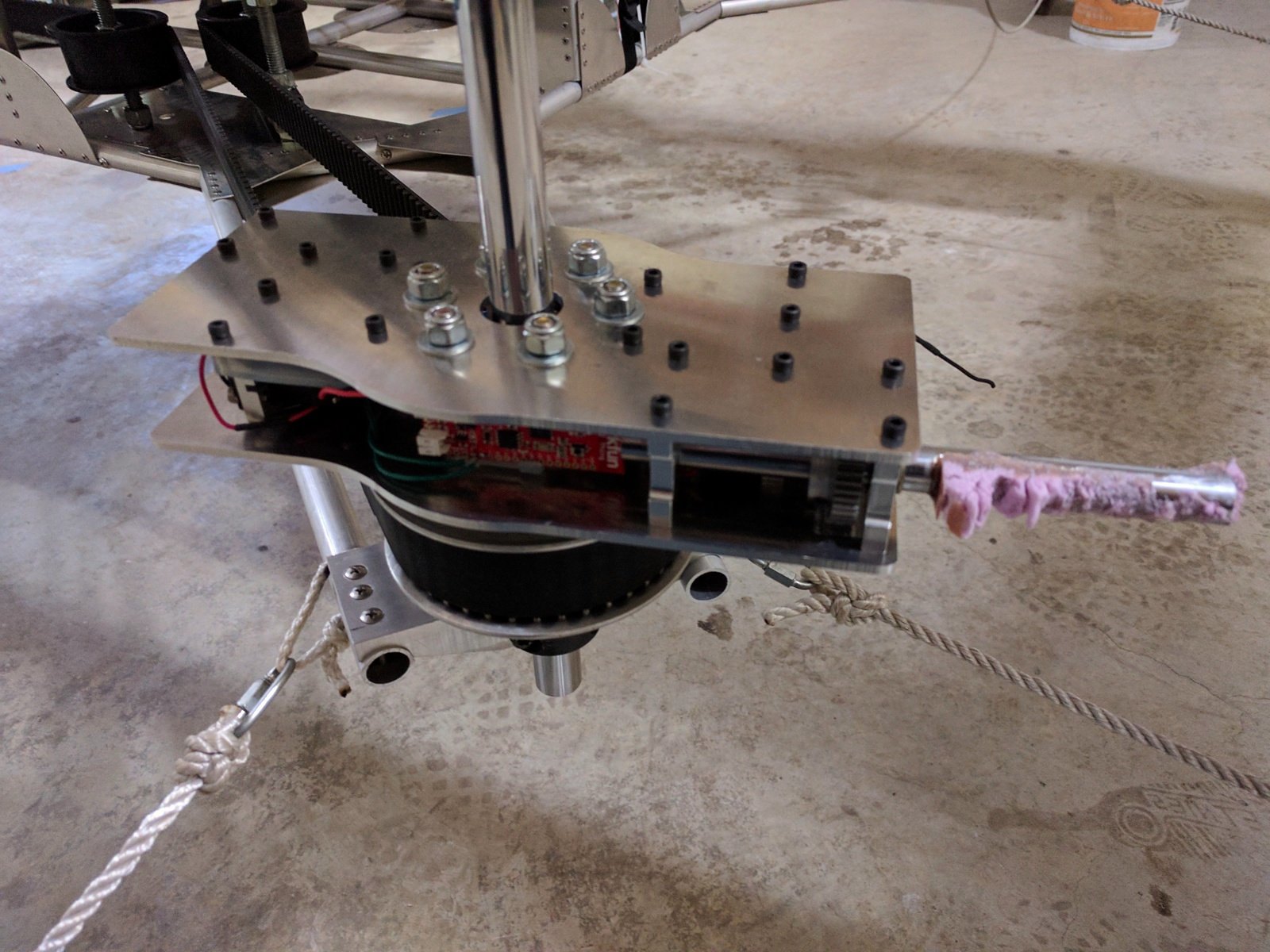
Prototype Repair, Working Power Supply
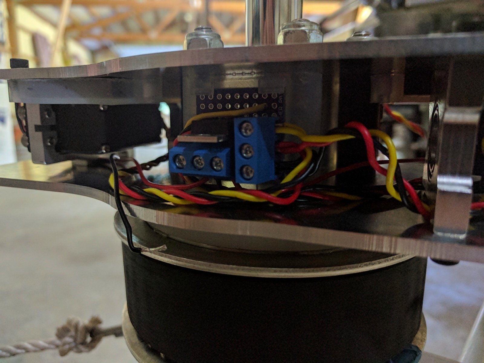
07/24/2017 at 01:26 • 0 commentsWhile it's impossible to know the exact sequence of failures during the previous test, it's clear that losing power was a contributing factor. Using small gauge solid wires with soldered connections and standard servo connectors was a poor choice considering the high vibration environments.
The power supply board was re-worked afterwards to come up with a better design. The connectors for the servos and the batteries are all screw terminals now and all of the solid core wires have been eliminated. The image below shows the power supply board with the screw terminals.
![]()
Another test was conducted, this time with just the electronics powered and the blades and axle removed (The replacement parts aren't ready quite yet, but I wouldn't have put them on for this test anyways).
The test was a success. The start-up and shut-down sequence was conducted a total of four times and the electronics never lost power. I should have done a test similar to test before attaching the blades in the first place, which would have eliminated some of the re-work I'm having to do now.
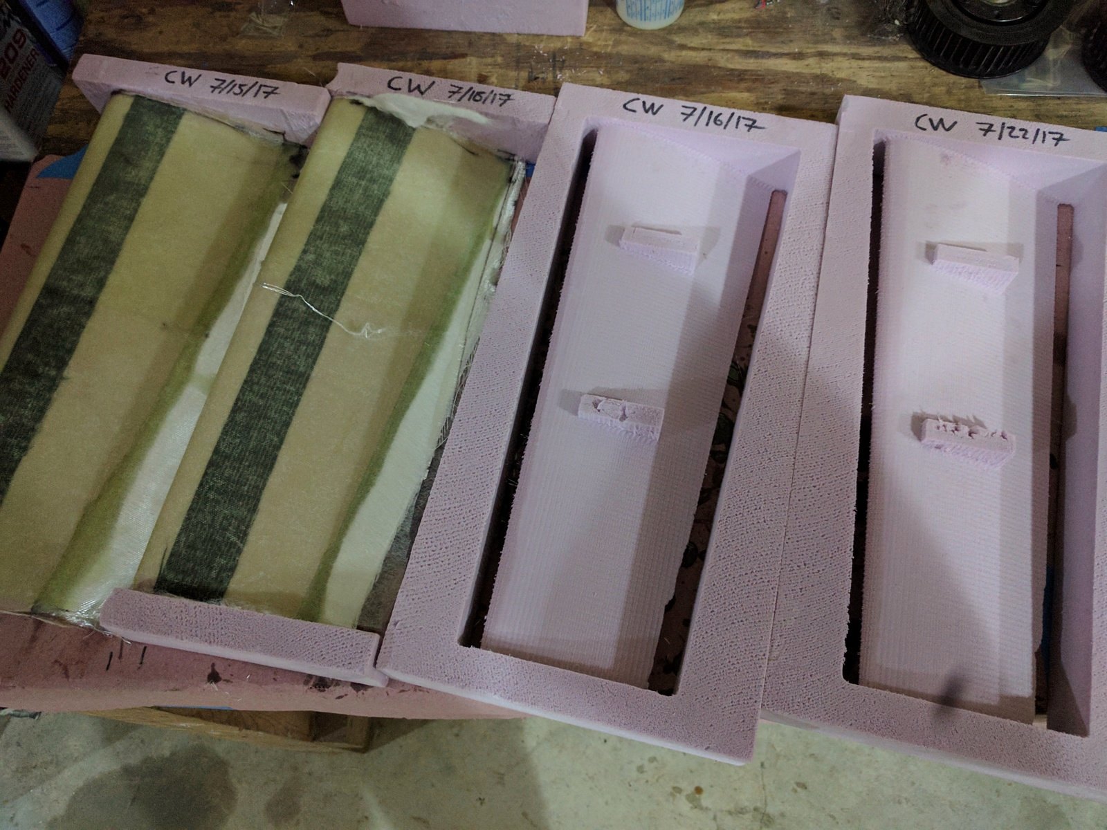
The new blades are nearly complete and a spare set is in-work to ensure that if there is another failure, the project won't get slowed down. Below is the two epoxied blades and the cores for two more space blades.
![]()
One other design change in the works is the addition of thrust bearings. The hardware for that will get here tomorrow and then the blades will be ready to be installed with the thrust bearings. If everything goes smoothly, the full prototype will be assembled again and ready for testing by the end of the week.
-
First Full Prototype Tests, Prototype Broken
07/16/2017 at 16:27 • 0 commentsThe first full prototype had been assembled and some basic firmware was written to do some simply tests. The first was a self test where the on-board ESP32 command the servos to sweep through the servo travel range. Below is the video of the self-test.
Note that the servos have way more range than is actually required. More gearing could be added, but that would mean a loss in response time. It was decided to keep the current travel range, but limit the range in software.
For the next test, the firmware was setup simply hold the blades at a specified angle of attack. The blade angle was set to a near zero lift condition (Due to the blade twist, the isn't really a true zero lift condition). The position hold functionality was tested by attempting to twist the blades by hand and the blades maintained their specified position. With the firmware functionality confirmed, the vehicle was turned on to test out the full prototype similar to the hub spin up test done a few weeks ago.
The test didn't go well. The vehicle had an unusually hard start-up, causing the vehicle to flex more than usual. Shortly afterwards the electronics on the rotor lost power. Afterwards, it's hard to determine exactly what happened next. Even at 60 fps, the blades are spinning too fast to see what's going on. However, without power, the servos can't maintain the blades. It's possible that they rotated into the belts and were subsequently ripped off.
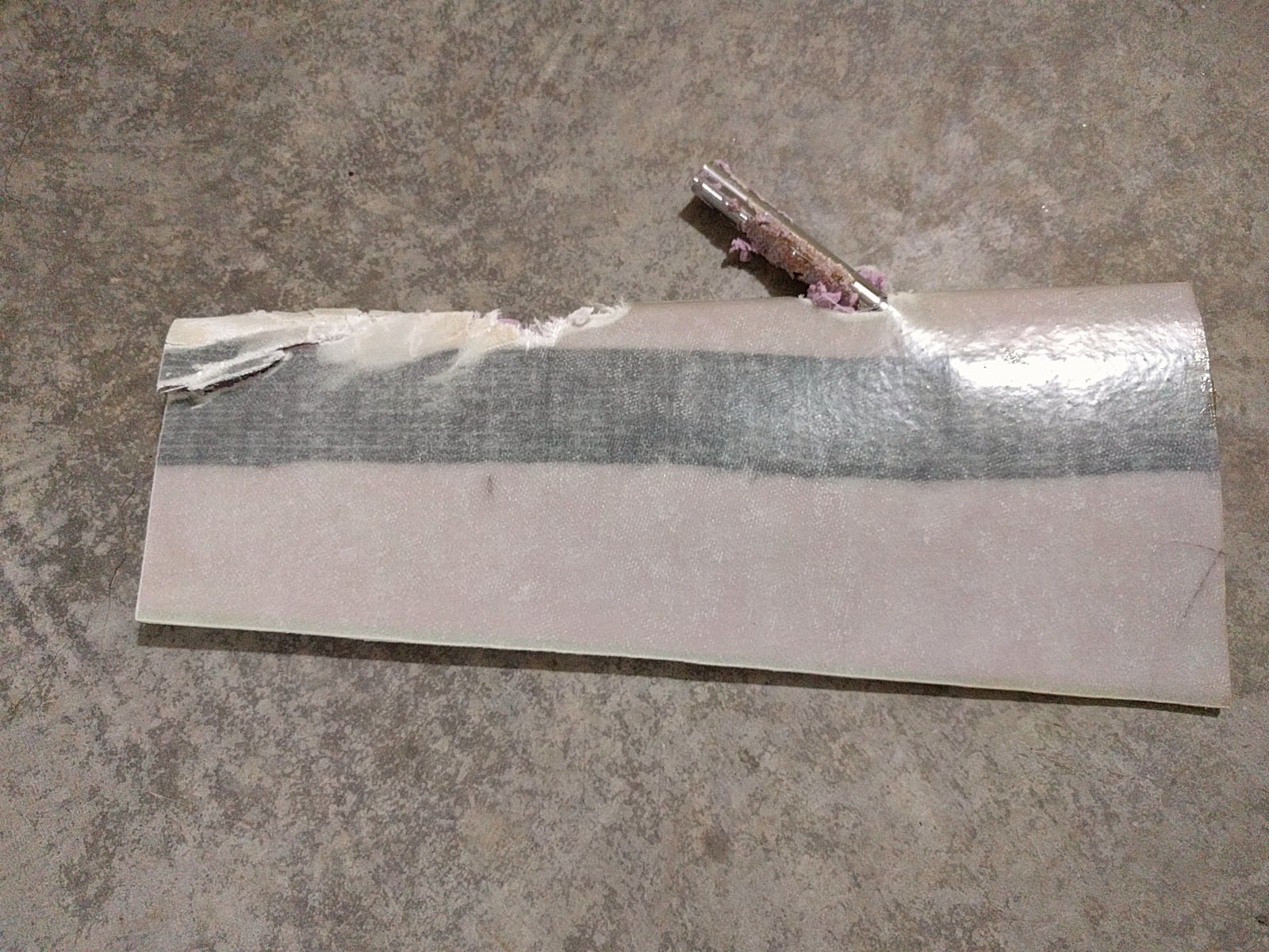
Here's a photo of the rotor after the test. One of the blades was simply ripped from the axle. It appears that the bonding between the shaft and the blade wasn't that great in places. The black wire is the battery wire that became disconnected during the test.
![]() The other blade (the one that bounces page into the frame in the video) took the axle with it. To do this, one of the retaining rings and the steel gear had to be stripped off (I still haven't found either of those pieces in the shop). It appears that when the blade impacted the wall, the axle was kept going and popped out through the blade.
The other blade (the one that bounces page into the frame in the video) took the axle with it. To do this, one of the retaining rings and the steel gear had to be stripped off (I still haven't found either of those pieces in the shop). It appears that when the blade impacted the wall, the axle was kept going and popped out through the blade.![]() Repairs are in-work and shouldn't take too long. More robust power connections are needed. I'll start with slightly bigger wires and screw-down style terminal blocks. Mechanical limit stops will also be added to prevent the blades from rotating too far. It'd probably also make sense to add some additional clearance between the rotor and the belts.
Repairs are in-work and shouldn't take too long. More robust power connections are needed. I'll start with slightly bigger wires and screw-down style terminal blocks. Mechanical limit stops will also be added to prevent the blades from rotating too far. It'd probably also make sense to add some additional clearance between the rotor and the belts.UPDATE (7/16/17 10PM PDT)
I finally found the missing gear today! The gear was embedded in the foam enclosure around the CNC router. The 2" thick foam was the best possible material for the gear to impact and the steel gear is completely unharmed.
![]()
EVPR: Electric Variable Pitch Rotor
An electrically actuated variable pitch rotor with a wireless interface


 ESP32 is connected via on of the UARTS to the TELEM2 port on the Pixhawk. The Pixhawk sends out messages via the
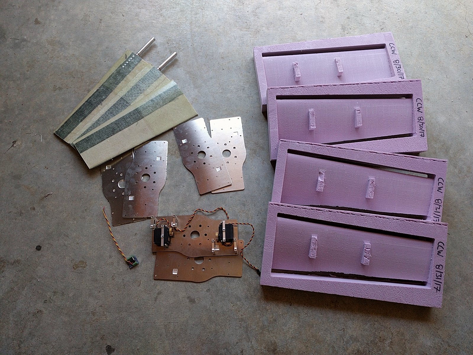


 Repairs are in-work and shouldn't take too long. More robust power connections are needed. I'll start with slightly bigger wires and screw-down style terminal blocks. Mechanical limit stops will also be added to prevent the blades from rotating too far. It'd probably also make sense to add some additional clearance between the rotor and the belts.