Peter McCloud
-
Blade Construction
07/11/2017 at 01:20 • 0 commentsThe previous project log showed the assembled prototype complete with rotor blades. However, the construction of the blades for EVPR hadn't been documented. The rotor blades use a similar process as what's documented in #Inexpensive Composite Propellers/Rotors, but with a few tweaks.
![]() The blades are built using a composite layup process. The image above shows all of the materials that go into making the rotor blade. The process starts with the pink object, which is the foam core. The core is cut into the shape of the rotor blade using a CNC router. The core as shown above is after the supports have been trimmed off.
The blades are built using a composite layup process. The image above shows all of the materials that go into making the rotor blade. The process starts with the pink object, which is the foam core. The core is cut into the shape of the rotor blade using a CNC router. The core as shown above is after the supports have been trimmed off.To start, epoxy is mixed and a thin layer is applied to the core. Next, the two strips of uni-directional carbon fiber tape (The two black strips on the far right) are applied over the quarter chord on the top and bottom of the blade. Next, 3 layers of fiberglass (white woven fabric in the image) are applied individually and wetted out with epoxy as they are applied. The fiberglass is then covered with Aeroveil (gauze looking material below the fiberglass fabric in the image) which gives the composite a smooth finish when complete.
The next step is to wrap the blade with peel ply (green plastic) which keeps the bagging material from sticking to the epoxy and then with breather cloth (white felt) and then everything is placed it n the vacuum bag (yellowish plastic).
![]() When vacuum is applied to the bag, the air is removed and the excess resin is sucked through tiny holes in the peel ply and into the breather cloth. This makes the part as light as possible. Below is the part after the epoxy has cured and the item has been removed from the vacuum bag.
When vacuum is applied to the bag, the air is removed and the excess resin is sucked through tiny holes in the peel ply and into the breather cloth. This makes the part as light as possible. Below is the part after the epoxy has cured and the item has been removed from the vacuum bag.![]() Finally the ends are trimmed off, and the axle is attached. This is done by drilling a hole into the root side and using epoxy to adhere the axle to the blade. With the axle attached, the blades can then be installed onto the hub.
Finally the ends are trimmed off, and the axle is attached. This is done by drilling a hole into the root side and using epoxy to adhere the axle to the blade. With the axle attached, the blades can then be installed onto the hub.![]()
-
Blades and electronics added to the first prototype
07/05/2017 at 03:56 • 0 commentsThe rotor blades and the electronics are now complete and have been added to the hub.
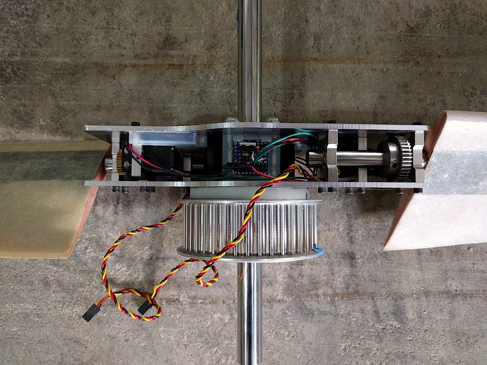
![]() For now, the prototype will just be operated on battery power. Once the rotor has been tested, and shown to work, then the primary power source will be added.
For now, the prototype will just be operated on battery power. Once the rotor has been tested, and shown to work, then the primary power source will be added.Two 3.7V LiPo batteries provide the power (and will be the backup source for the final version). The batteries are tied together to provide the 7.4V needed to drive the servos. A voltage regulator is mounted on one half of the hub and provides power for the ESP32 dev board on the other side of the hub.
Small proto-board with battery connections and voltage regulator.
![]() ESP32 dev board.
ESP32 dev board.![]() The hardware is now ready to test all of the capabilities, except for the primary power source. The next step is to develop the Firmware so that more complex testing can begin
The hardware is now ready to test all of the capabilities, except for the primary power source. The next step is to develop the Firmware so that more complex testing can begin -
Prototype Hub Spin Up Test
06/21/2017 at 04:46 • 0 commentsThe prototype hub was assembled with just the mechanical components. (No batteries, controller or blades). It was decided that it'd be good to do a quick test to ensure that the assembly would hold together before proceeding further with the rest of the project. Therefore the hub was mounted onto the vehicle and a quick spin up test was performed.
The hub held together, so the next step will be adding the batteries and the controller board. I've also started making the first set of rotor blades, which I'll document in a future build log.
-
Batteries selected
06/09/2017 at 02:31 • 0 commentsWhile the primary power source for the rotor will eventually be an axial flux generator, batteries will be present to provide startup power and serve as a backup. The latest servos, HS-5685MH, run at 7.4 V max and draw a maximum current of 2700 mA.
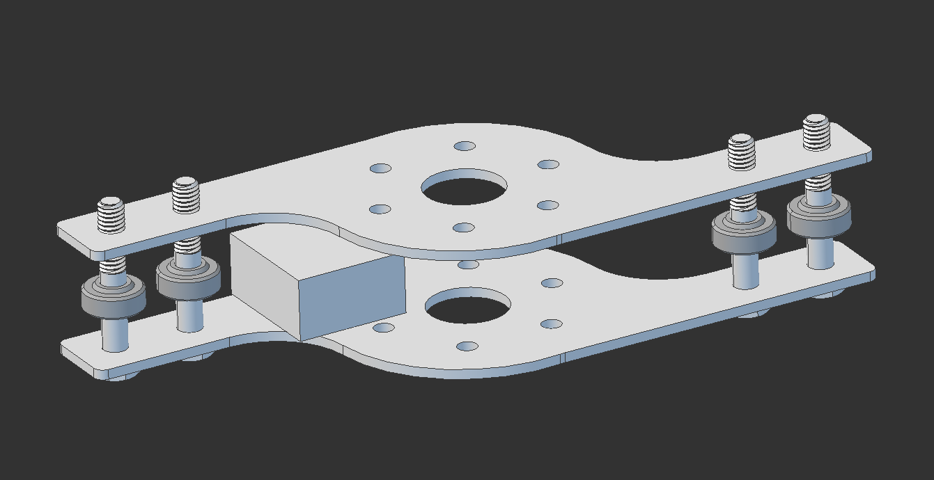
Packaging was the primary driver for the battery selection. It was desired to have batteries that would fit inside of the hub. The battery chosen was the UBP053450/PCM. This battery will tuck into the gap between the servo and the upper plate and the main mounting bolts. The batteries are highlighted in blue in the figure below.
![]() Each of the batteries have 900 mAh, so the total capacity is 1800 mAh. This is sufficient to provide 10 min of operation time at the maximum stall current for both servos, and should be adequate for controlling the vehicle if the axial flux generators fail.
Each of the batteries have 900 mAh, so the total capacity is 1800 mAh. This is sufficient to provide 10 min of operation time at the maximum stall current for both servos, and should be adequate for controlling the vehicle if the axial flux generators fail.The batteries should arrive next week. In the meantime a design for the battery clip needs to be created. After that, the ESP-32 dev board can be mounted inside the hub and the electronics testing can begin in earnest.
-
Second Prototype Assembled, Gear Drive Test
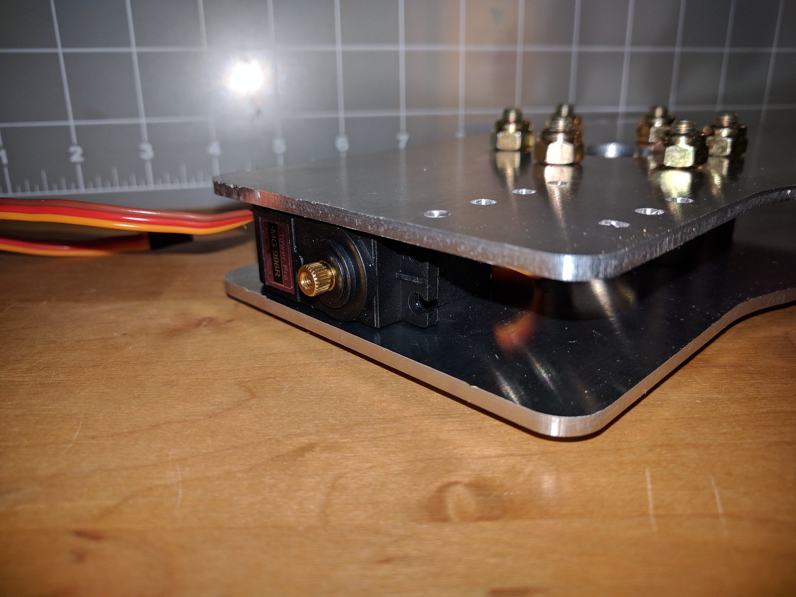
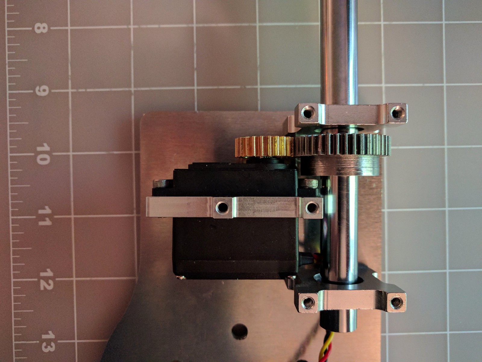
06/03/2017 at 01:48 • 0 commentsThe mechanical elements of the second prototype was assembled today and the gear drive was tested. Below is a short video of the gear drive in action (Note that the top plate is removed to share the gear movement. For this test, a temporary power supply was wired up with two 3.7V LiPo batteries to get a 7.4V power supply and a spare RC reciever was used to provide the signals.
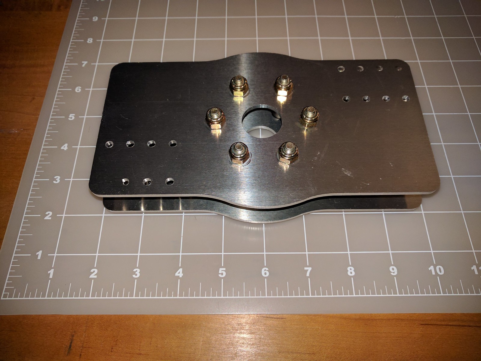
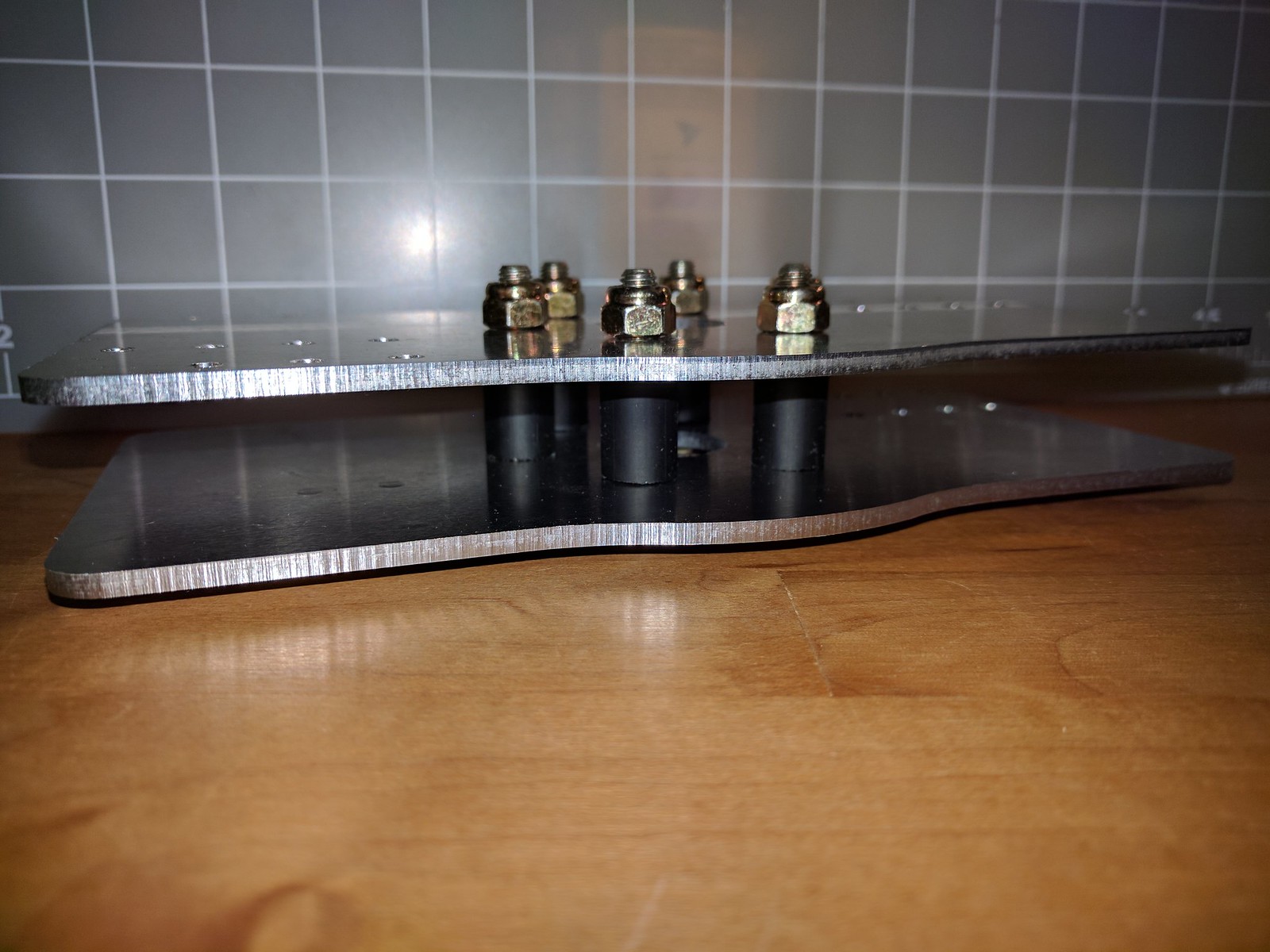
The pillow blocks, servo mounts, and the servo gear are all off the shelf components. The shaft gear was custom made from gear stock. Below is a picture of the gear, which also includes a set screw for mounting to the shaft.
![]() Here's an overhead view of the gear and servo on one half of the rotor.
Here's an overhead view of the gear and servo on one half of the rotor.![]()
The next step is to put the hub on the quadcopter to check the fit and the clearances. Then the quadcopter will be run with the hub in place to make sure that the assembly holds together. If that works then it'll be onto wiring up the prototype electronics and making the first set of blades.
-
Gear Drive Re-design
05/27/2017 at 05:12 • 0 commentsA few weeks back I assembled the major mechanical components for the first EVPR prototype. Shown below
![]() This prototype used a simple Acetal bushing. This was done to keep the design simple and the weight down. After assembly, it became apparent that this wouldn't work as well as hoped. The dimensional stability is less than desired. When originally assembled, the shaft and bushing fit was acceptable, but with variations in temperature and the torque on the screws, the fit is quite variable.
This prototype used a simple Acetal bushing. This was done to keep the design simple and the weight down. After assembly, it became apparent that this wouldn't work as well as hoped. The dimensional stability is less than desired. When originally assembled, the shaft and bushing fit was acceptable, but with variations in temperature and the torque on the screws, the fit is quite variable.The second issue was the lever arm concept for rotating the shaft with the servo. The mechanical movement wasn't working smoothly and the movement range on the shaft was less than desired.
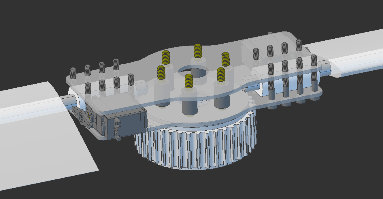
After researching different configurations, it was decided to change the bushings to bearings and use a gear drive instead of a lever arm to rotate the shafts. Even better, most of the hardware needed could be source for a reasonable price from Servo City. A new branch was created for the repository and after a quite a bit of CAD work, playing around with various configurations, a gear drive re-design was settled upon. A screenshot of the geared setup is shown below:
The servo has a 24 tooth brass gear that fits directly onto the servo spline. On the shaft is a 40 tooth steal gear giving a gear ratio of 5:3. The shaft is supported by two pillow blocks. The only piece that needs to be custom made is the steel gear. That will be machined out of gear stock from McMaster Carr. The servo, servo gear, servo mount and pillow blocks are all off the shelf hardware from Servo City.![]()
The hardware was ordered earlier this week and most of it's already been delivered, so if things go smoothly, the goal is to have the second prototype ready by end of Memorial Day weekend. Below are the hardware bits that came from Servo City yesterday.
![]()
I also plan to have more details of the servo sizing and selection in the near future.
-
Prototype Mechanical Components Assembled
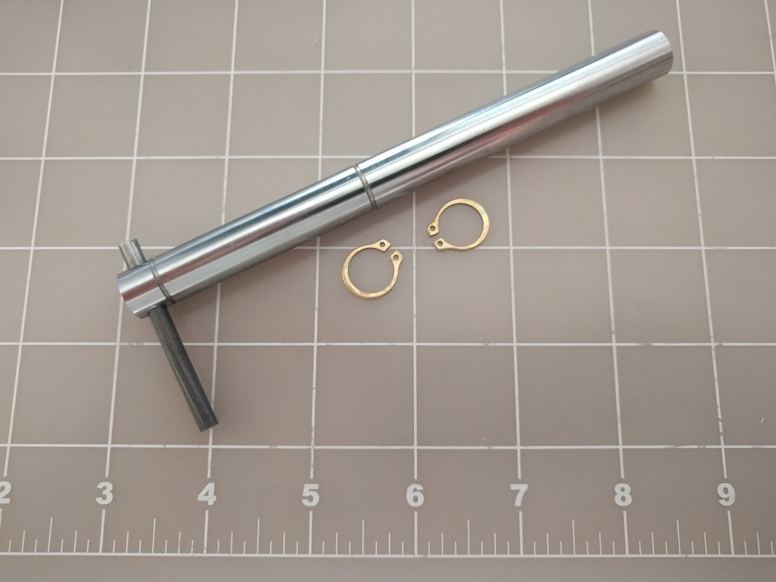
05/05/2017 at 02:52 • 0 commentsThe shafts have been completed and added to the prototype completing the mechanical portion of the rotor hub.
![]()
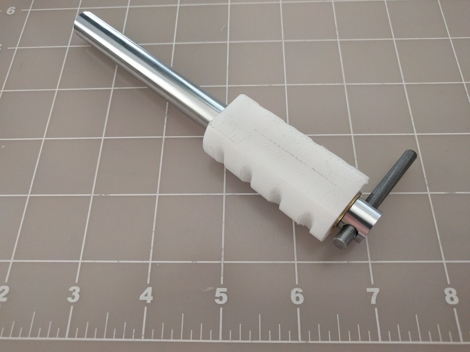
The method for interfacing the servo to the shaft is a little more concrete now.A lever was added to the shaft that will be used to rotate the shaft. The lever is a 3/16" piano wire 2" long. A 3/16" hole was drilled through the end of the shaft on the interior side of the shaft instead of the outside of the shaft.
![]()
![]()
![]()
There are a few benefits to having the lever on the interior side:
- The hole for the lever doesn't decrease the strength of the shaft.
- The lever is now protected inside the hub and less susceptible to damage.
- If the servo or linkage fails, the lever is captive between the two plates, limiting the travel of the blades if such a failure was to occur. This could mean the difference between losing the vehicle or not.
Drilling the 3/16" hole through the hardened steel shaft was an educational experience. Typical drill bits won't do much more than scratch the surface. I was about to buy some specialty bits when the intertubes provided some very useful information. Turns out that masonry bits with a carbide tip work well at cutting hardened steel. Just go slow and use cutting fluid. Since I had some masonry bits on hand it saved me some money as well as time. The process I ended up using was using a countersink to mark the location. A 5/32" masonry bit to drill the pilot hole and a 3/16" standard metal bit to clean up the hole to the proper diameter.
With the mechanical portion of the hub complete, the next step will be integrating the servos. The mechanical portion of the assembly weighs 2.0 lbs, an encouraging number.
-
First Bushing Complete
04/29/2017 at 18:05 • 0 commentsThe first bushing has been completed and mounted on the prototype. The bushings are machined from Acetal.
![]() The bushing was cut from tubular stock. In theory starting the tubular stock might have made making the part easier, but the ID had to be bored slightly larger anyways and machining the grooves in the side was kind of pain. If I stick with Acetal bushings in the future, I may switch to rectangular stock and make through holes for the bolts.
The bushing was cut from tubular stock. In theory starting the tubular stock might have made making the part easier, but the ID had to be bored slightly larger anyways and machining the grooves in the side was kind of pain. If I stick with Acetal bushings in the future, I may switch to rectangular stock and make through holes for the bolts. -
First Hardware Pieces Completed
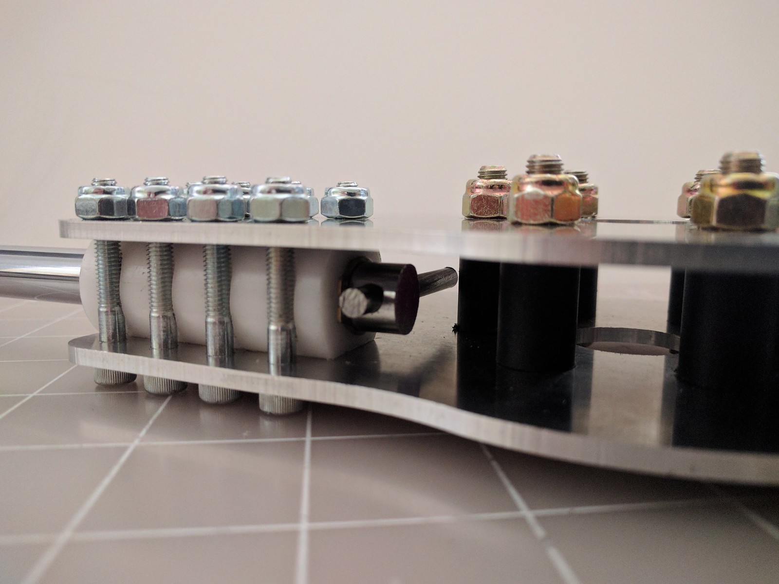
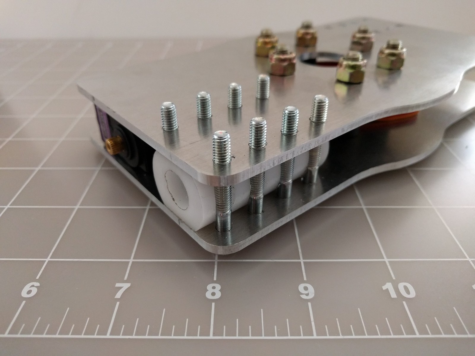
04/18/2017 at 03:54 • 0 commentsThe first EVPR prototype is starting to take shape. Over the weekend the first set of aluminum plates and polypropylene spacers made. The plates were cut from 0.125" thick 6061-T6 plate. The spacers were cut from a 12" long piece of stock. Below are some pics with the plates and spacers bolt together. For now a short set of bolts are used just to hold the hardware together. Eventually the whole assembly will be attached to the pulleys with longer bolts.
![]()
![]() One of the servos was placed between the plates to ensure the spacers were cut correctly. An attachment method for the servos still needs to be determined.
One of the servos was placed between the plates to ensure the spacers were cut correctly. An attachment method for the servos still needs to be determined.![]()
-
Bearings
04/13/2017 at 15:32 • 0 commentsThe design of the hub is progressing and the CAD is taking shape. Below is a closeup of the rotor hub.
![]()
The bearings will be made from acetal bushing stock cut to length. Typically, spherical ball bearings are used, but the loads for #Goliath - A Gas Powered Quadcopter are relatively low compared to full scale helicopter rotors and spherical bearings are pricey. A potential problem using the acetal could be a short life. In case that happens, a secondary design with spherical bearings is also being created as time allows.
Below is a screenshot of the secondary design. It's gives an idea of how the spherical bearings would replace the acetal bushing. The bearings would be embedded in the blade and pivot around the two bolts. It could be possible to keep the two design paths similar so that if a switch needs to be made, it should be a minimal disruption to the process.
![]()
The first batch of hardware should be here by the weekend, so the first prototype should start taking shape soon.
EVPR: Electric Variable Pitch Rotor
An electrically actuated variable pitch rotor with a wireless interface
 The blades are built using a composite layup process. The image above shows all of the materials that go into making the rotor blade. The process starts with the pink object, which is the foam core. The core is cut into the shape of the rotor blade using a CNC router. The core as shown above is after the supports have been trimmed off.
 When vacuum is applied to the bag, the air is removed and the excess resin is sucked through tiny holes in the peel ply and into the breather cloth. This makes the part as light as possible. Below is the part after the epoxy has cured and the item has been removed from the vacuum bag.
 Finally the ends are trimmed off, and the axle is attached. This is done by drilling a hole into the root side and using epoxy to adhere the axle to the blade. With the axle attached, the blades can then be installed onto the hub.
 ESP32 dev board.
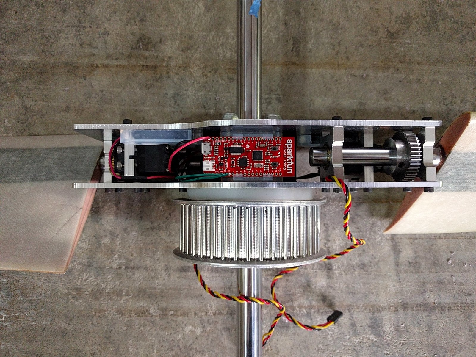 The hardware is now ready to test all of the capabilities, except for the primary power source. The next step is to develop the Firmware so that more complex testing can begin
 Each of the batteries have 900 mAh, so the total capacity is 1800 mAh. This is sufficient to provide 10 min of operation time at the maximum stall current for both servos, and should be adequate for controlling the vehicle if the axial flux generators fail.
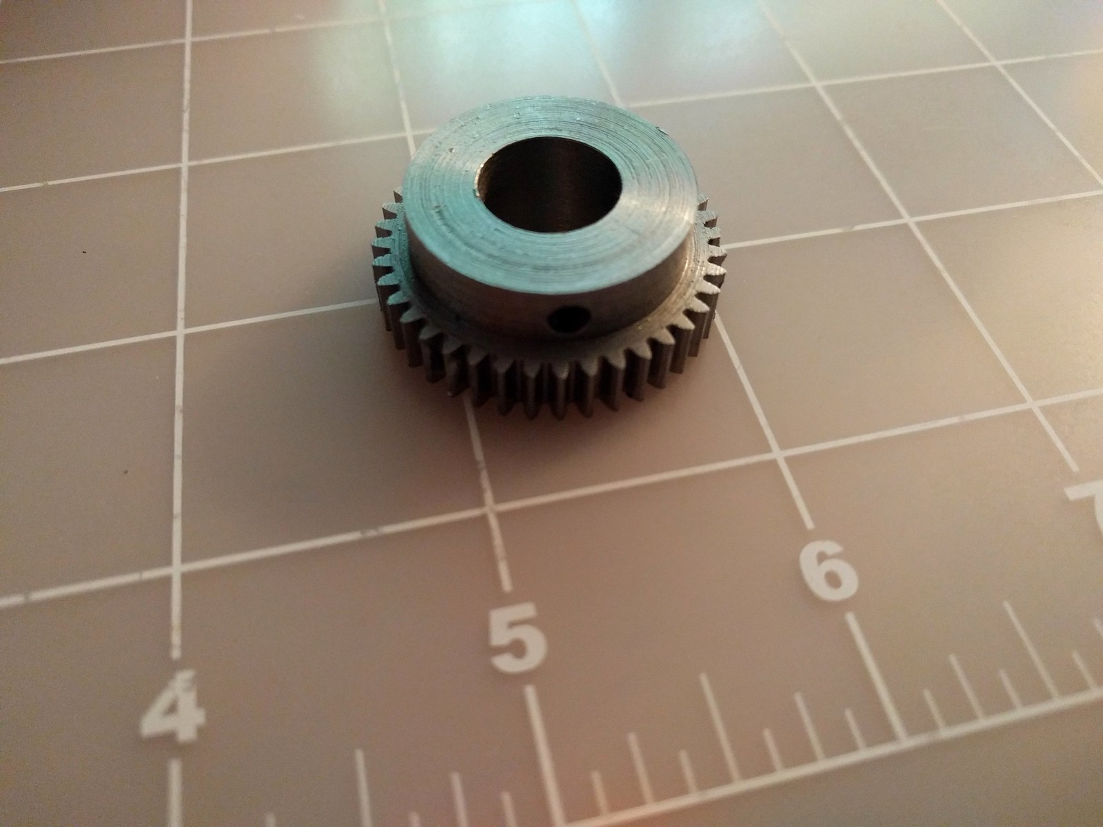
 This prototype used a simple Acetal bushing. This was done to keep the design simple and the weight down. After assembly, it became apparent that this wouldn't work as well as hoped. The dimensional stability is less than desired. When originally assembled, the shaft and bushing fit was acceptable, but with variations in temperature and the torque on the screws, the fit is quite variable.
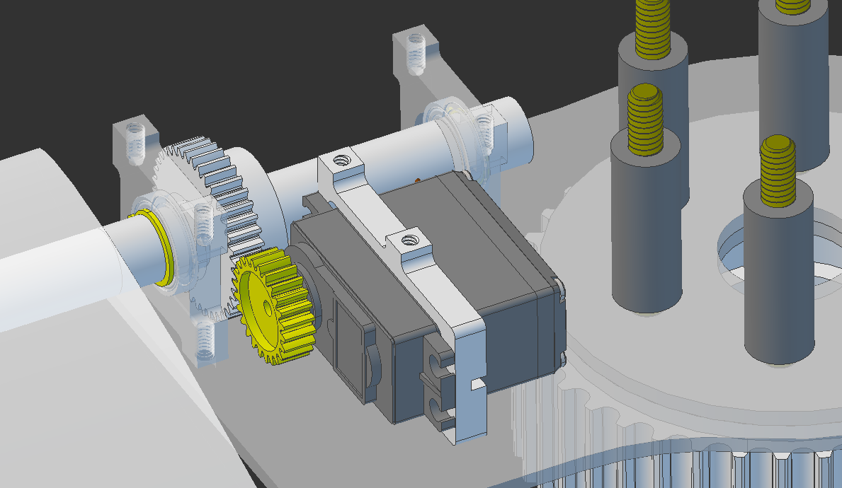


 The bushing was cut from