 Osman Mazinov
Key Features:
- GPIO Interface: 4 buttons for user input (active low).
- Load Control: ULN2003 Darlington array driving two 12V relays and status LEDs.
- Analog Sensing: 2-channel 10-bit ADC (MCP3008) via SPI with input RC filters.
- Environment: Dedicated 1-Wire header for DS18B20 temperature sensors.
- Timekeeping: DS1307 Real-Time Clock (RTC) with battery backup and MOSFET level shifters.
- Industrial Comms: RS485 interface (ST485) with an automatic direction control hack.
- Integrated Power: Onboard transformer-based PSU (5V for logic, 12V for relays).
Power Supply & Logic
The board features a dual-output transformer. One rail feeds a 5V linear regulator for the RS485 driver and RTC. The second rail provides 12V for the relay coils and the ULN2003. Logic level translation is handled by VT2/VT3 MOSFETs for the I2C bus (3.3V to 5V).
The RS485 "Auto-Direction" Hack
To save GPIO pins, I implemented a transistor-based (VT1) circuit for the ST485 driver. The chip switches to transmit mode only when the UART is actively sending data. Otherwise, it defaults to receiving. This was successfully tested using ModBus RTU at 115,200 baud.
Analog Inputs
For simplicity and academic purposes, I used an MCP3008. While it works great for basic debugging, for high-precision measurements, I recommend isolating the digital and analog grounds and using an external voltage reference.
Software & Prototyping
I used Python scripts to verify the SPI (ADC) and I2C (RTC) functionality. Even with basic coding skills, the hardware proved easy to integrate within the Raspbian environment.
Resources
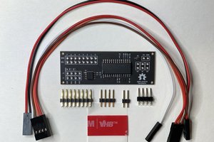
The project was designed in DipTrace. You can find the schematics, PCB layouts, Bill of Materials (BOM), and Python test scripts in my repository.
- PCB Software: DipTrace
- Communication: SPI, I2C, UART (RS485), 1-Wire
- Language: Python (for testing)
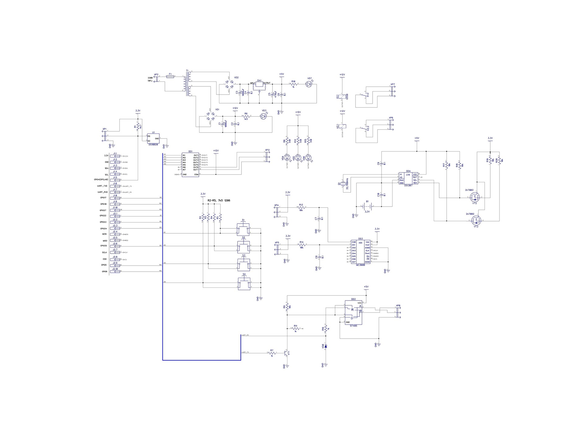
Schematic diagram
 Steven Stallion
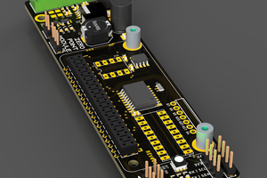
 pkElectronics
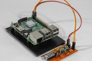
 Dilshan Jayakody
 piplay