 Frank Buss
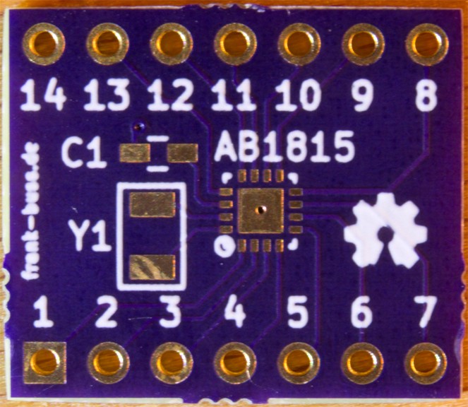
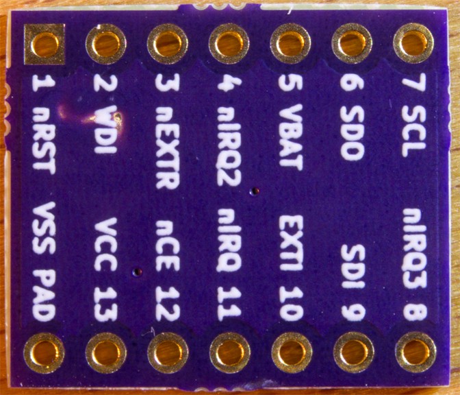
I got the PCBs from @oshpark for my breakout board for the RTC chip:
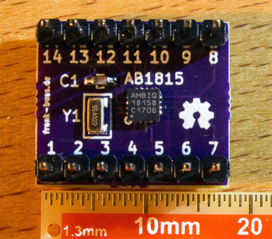
With some solder paste and my heatgun I managed to solder the QFN IC and the other two parts:
A quick test with my STM32 discovery board, generating some SPI signals shows that it is ticking, when I read the seconds register:
Note the jump from 0x19 to 0x20. This is because it counts in BCD mode.
Discussions
Become a Hackaday.io Member
Create an account to leave a comment. Already have an account? Log In.
Thanks for sharing.
If you extend the lands for the QFN package outside the package outline, it could be handsoldered, and especially touched up if there is some paste problem. You might need to design your own footprint. Typical of KiCad it might be named e.g. QFN16_4x4_handsolderable.
I think the XTAL is needed for best accuracty. The part has three modes: xtal, autocalibrated RC, and RC, from most accurate and most current to least accurate and least current. The xtal is needed for the first two modes. In the autocalibrated mode, the chip periodically calibrates the RC osc agains the xtal osc, so the xtal osc is not always running, and therefore that mode is almost as accurate as xtal mode, but takes less current. See the whitepaper from Abracon about autocalibration.
Are you sure? yes | no
How did you apply the solder paste? Did you use a stencil?
Are you sure? yes | no
I used a syringe and a toothpick. If you don't use too much solder, it doesn't matter if it is applied between the pins of the QFN-IC as well, when it melts, it flows and sticks to the pins and pads.
Are you sure? yes | no
nice board and very interesting to see the visualization on the scope!
Are you sure? yes | no