 Sagar 001
Current sensing is very important as an electronics engineer for me, It made me think to grasp the topics of OPAMPs with a better approach. When I used to design my circuit in the past, I did not even look at the amplifier specs, just put a resistor and measure the voltage across it. Then amplifying it a bit and measuring with ADC. This method works well but introduces non linearity noise and errors. That's what I think is why my measured value drifts over voltage. The issue is I am using the minimal yet working setup because it is easy to do. And if you don’t care too much about accuracy of a few mA then this method is good to go. But with some optimal approach and adding a few more components increase the accuracy and reduce the overall noise.
In many of my battery-powered designs, I needed a simple and easy to measure current sensor without disturbing the system. In low-power systems, current variations are often subtle but critical:
- A microcontroller in sleep may draw a few microamps
- A sensor waking up may draw milliamps for milliseconds
- A battery charger may behave correctly in voltage but fail in current regulation
That requirement led me to design a compact high-side current sensing board using the CSA220 current-sense amplifier.
Using Current Sense Resistors:
Current itself is not measured directly. Instead, we convert it into a voltage using a current-sense resistor (shunt).
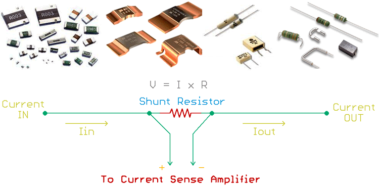
V_sense = I * R_sense
So if we are using a shunt resistor of 10 mΩ, then:
- At 1 A, sense voltage = 10 mV
- At 100 mA, sense voltage = 1 mV
These voltages are too small to measure directly with a multimeter or MCU ADC. That’s where the CSA220 comes in.
Why Not Use a Simple Op-Amp?
At first glance, it might seem tempting to amplify the shunt voltage using a regular op-amp. The limitations are in the internal circuits of OPAMPs.
Input Common-Mode Range: Every operational amplifier has an input common-mode range (ICMR), if the input voltage meets the ICMR range it works perfectly but produces non-linearities beyond that. Hence if a 5V opamp has ICMR of (0 to 3.5V) we can not apply a signal greater than 3.5 at the differential input.
Poor CMRR at High Voltage: Small sense voltages (µV–mV) riding on large common-mode voltages require extremely high common-mode rejection. It is basically how well the two signals cancel out if they are the same, defined for a range of voltages again!
Offset Voltage Dominance: When there is no signal or short condition then the input offset voltage due to the internal transistor mismatch in the opamp may create a voltage at output. When measuring 1–10 mV, even a few microvolts of offset introduces large errors.
Using Current Sense Amplifiers - CSA220
The CSA220 is a dedicated high-side current-sense amplifier, designed specifically for this task. And because of special internal architecture they have:
- Input common-mode range: 0 V to 76 V
- Low input offset voltage: typically 5 µV
- High CMRR: up to 157 dB
- Fixed, precision gain (10 V/V in my case)
These specs allow accurate measurement of millivolt-level signals even when the shunt is sitting at high voltage. We will discuss the basics of high side and low side current sensing in the end, but here is my minimal design of CSA 220.
Components Required:
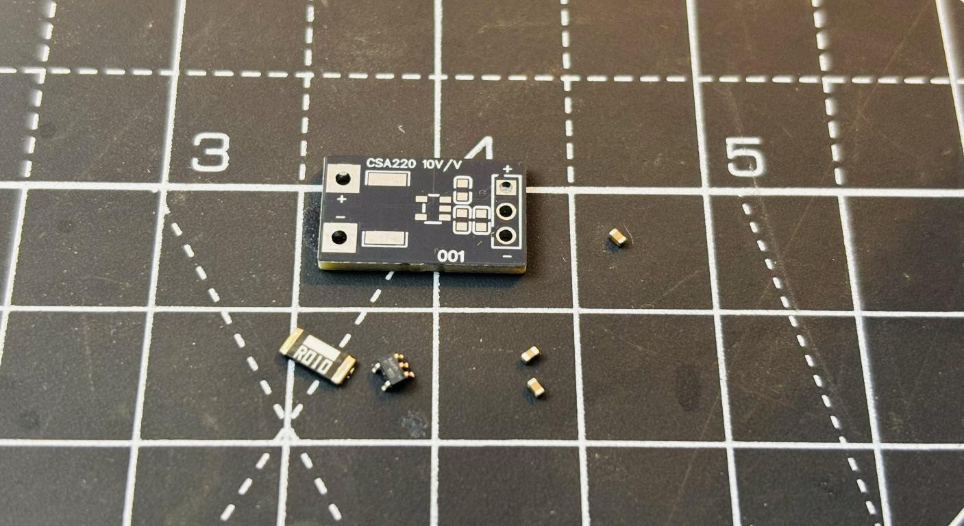
- CSA220
- 10 mΩ precision shunt resistor
- 100nF ceramic capacitor
- Pin headers
- 3V Power source
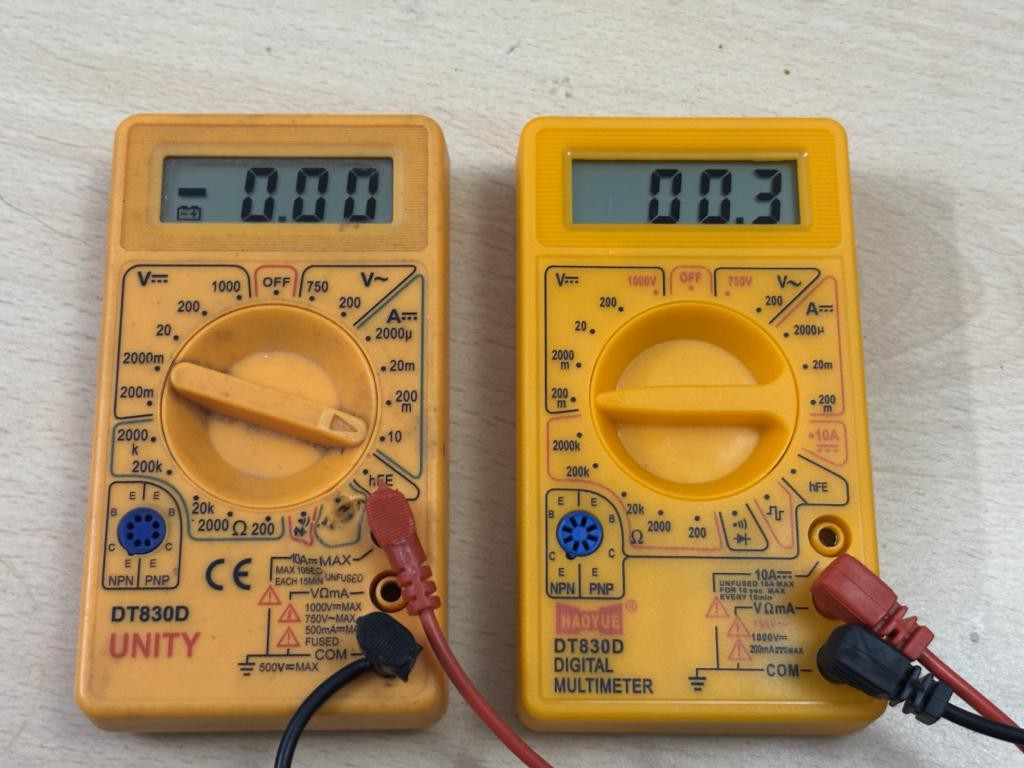
- Multimeter (basic)
Circuit Diagram and Schematics:
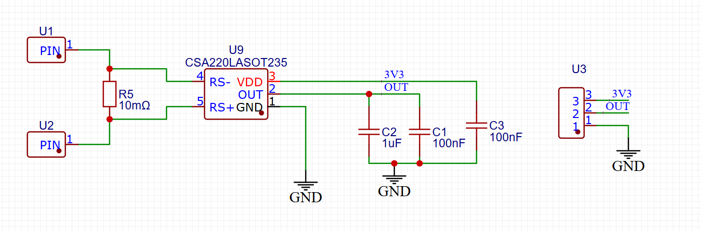
The circuit is very simple and uses minimal external components. I am using a 10 mΩ precision shunt resistor. The resistor chosen should be precise enough to 1% tolerance. CSA220-10, 10 V/V gain version is used in the schematics, to keep my multimeter calculations straight forward. Current is just a decimal forward form the output voltage. The output headers are placed on the other side, so we can plug it into any board and do the measurements. I have placed some decaps, I do want to follow the...
Read more »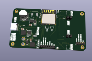
 Gangwa Labs
 Kuba Sunderland-Ober
 Lithium ION
 jbb
jbb