 Arnov Sharma
Greetings, everyone, and welcome back. This one’s a big build—meet the Parallel PC.

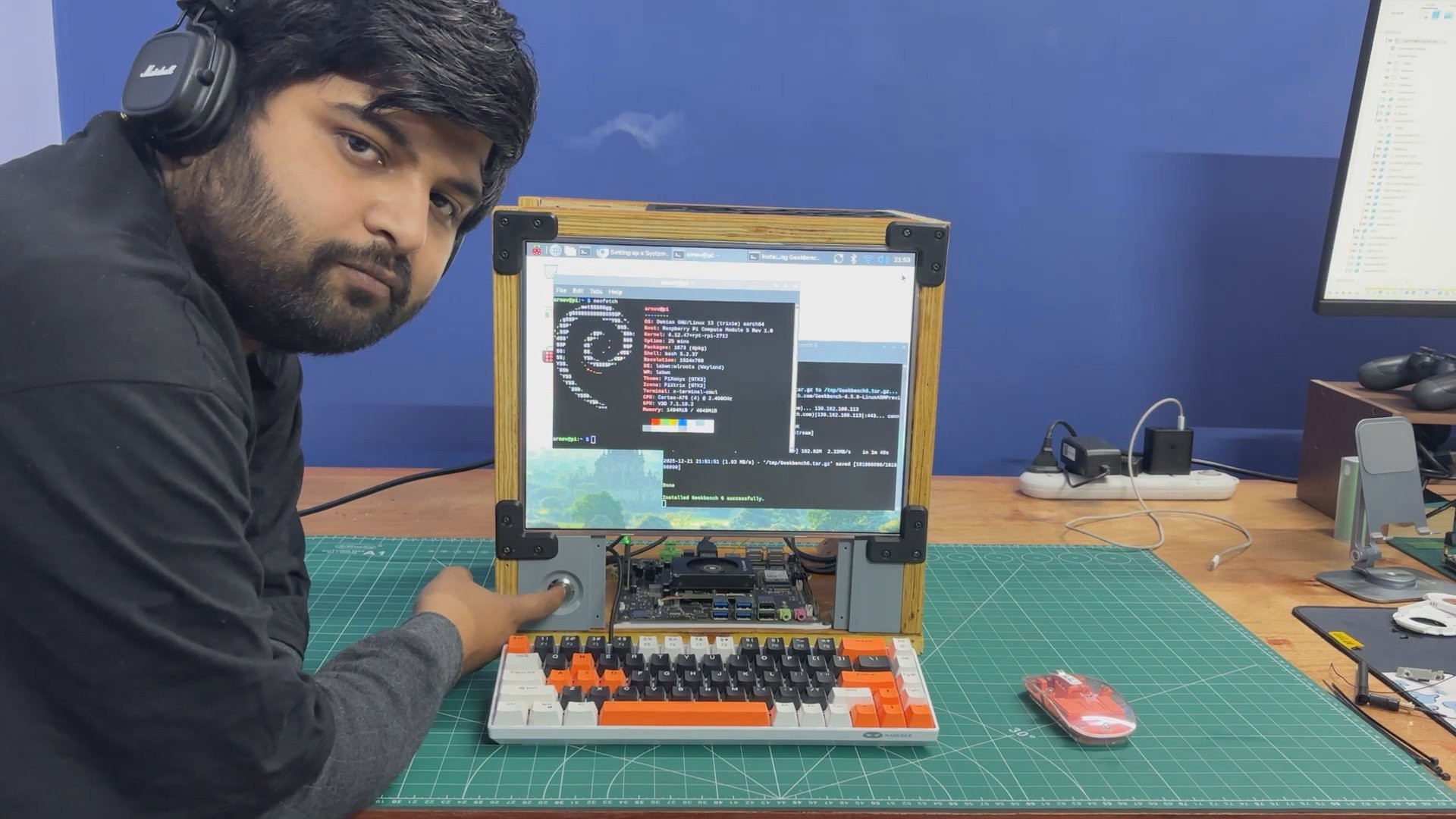
Parallel PC is a DIY all-in-one computer featuring a custom body made from wooden panels and 3D-printed parts, built around a 15-inch LED display. What makes it special is that it houses not one but two different single-board computers. One is the ARM-based Raspberry Pi Compute Module 5 with its official evaluation board, and the other is an x86-based LattePanda MU.
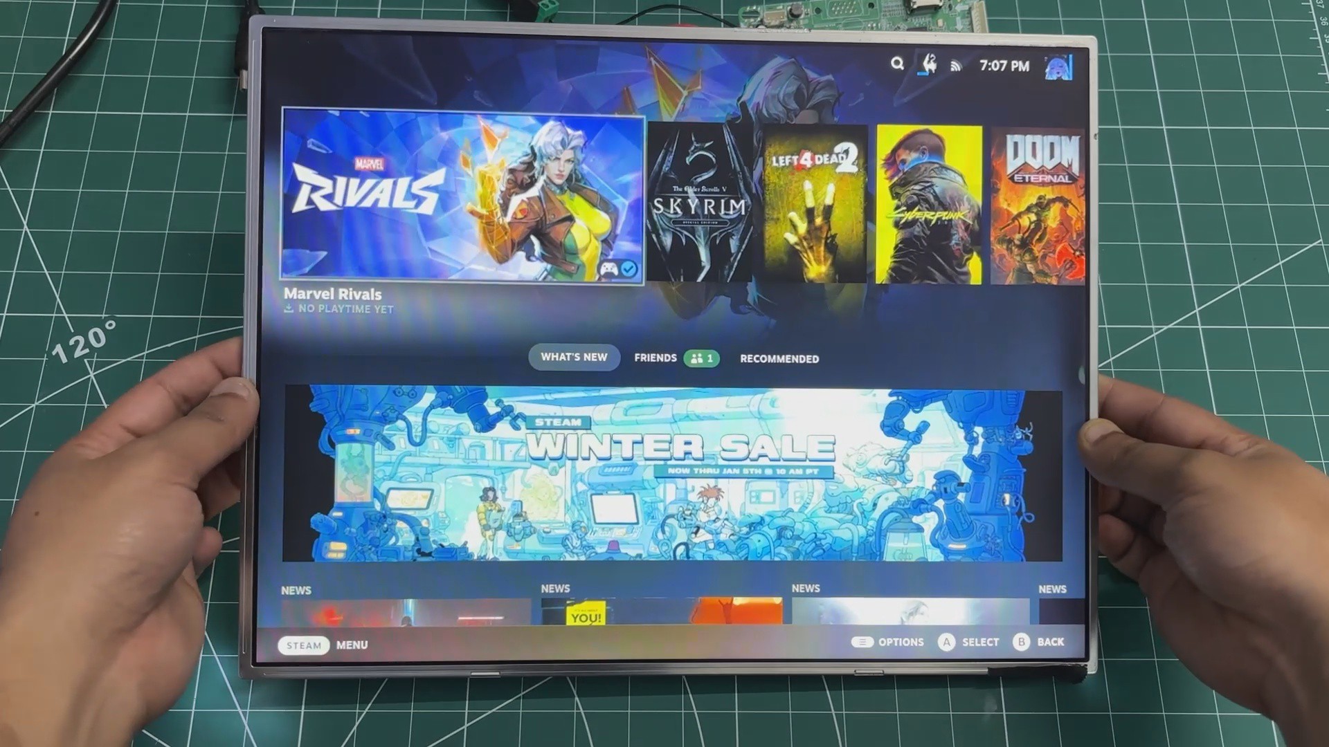
The idea behind this project was to take one of my previous builds—the WoodWorks Fusion PC—and transform it into a dual-compute system. With the press of a single button, the active computer connected to the main display can be switched instantly. If you want to work on Raspberry Pi projects, you switch to the Pi. If you need an x86 environment to run Windows or, in our case, Bazzite, you switch over to the LattePanda. One enclosure, one monitor, two completely different computing platforms.
Built using a combination of wooden panels and custom 3D-printed parts, this project is the starting point of the Parallel PC series. The goal is to keep evolving this enclosure—retrofitting new hardware, adding more single-board computers, and experimenting with different ideas over time.
This article covers the complete build process of the Parallel PC, from design to final assembly. Let’s get started with the build.
MATERIALS REQUIRED
These were the materials we used in this build:
- Custom PCBs (provided by PCBWAY)
- Woodwork Fusion PC Body (that includes all the wooden parts)
- Raspberry Pi CM5 with expansion board
- Type C to C PD Cable
- Lattepanda MU with Full Evaluation Board
- HDMI Splitter
- 15-inch LED Display along with its Driver (Salvaged from a new monitor)
- 12V 5A Mini SMPS
- Wood screws M4
- 3D-printed parts
- PD Buck Converter
- HDMI CABLE 0.5 METER
- HDMI BREAKOUT BOARD WITH FLAT CABLE
- M2 SCREWS
Woodwork Fusion PC

The original WoodWorks Fusion PCwas a custom all-in-one computer built from scratch using a combination of wood and 3D-printed parts, inspired by CyberDesk-style aesthetics.
The goal was not performance but form—creating a visually striking enclosure around deliberately outdated hardware, basically a potato PC.
At its core, the system used a 4th-generation Intel i3 desktop CPU mounted on a Mini-ATX motherboard, paired with 12 GB of DDR3 RAM and a GT 710 GPU. While the hardware was clearly obsolete, the enclosure was designed to be modular, allowing components to be easily upgraded in the future without changing the overall structure.
The body was primarily constructed from plywood, chosen for its strength and ease of fabrication. 3D-printed L-brackets were used to join panels together, forming a rigid cuboid enclosure capable of housing the motherboard, power supply, storage drives, and display.
DISPLAY


In the previous version of this project, we reused an old LCD monitor from around 2012. It was a Samsung 4:3 display, a format that was very common during the early days of LCD screens.
At the time, most content and applications were designed around this aspect ratio. As display technology evolved, wider screens became the standard, driven by changes in content consumption, improved productivity workflows, and the demand for more immersive experiences in multimedia, professional work, and gaming.
For this revised build, we switched to a much slimmer 15-inch LED display, salvaged from a low-cost monitor purchased for under $25.
We stripped down a low-cost monitor and reused its TFT panel for this project. The monitor’s HDMI driver board was retained, but its original power supply was intentionally omitted. Instead, the display is powered by the same SMPS used for the other internal components. This approach helped reduce the overall size of the wooden frame, making the final build more compact.
LATTEPANDA MU FULL EVALUATION BOARD SETUP
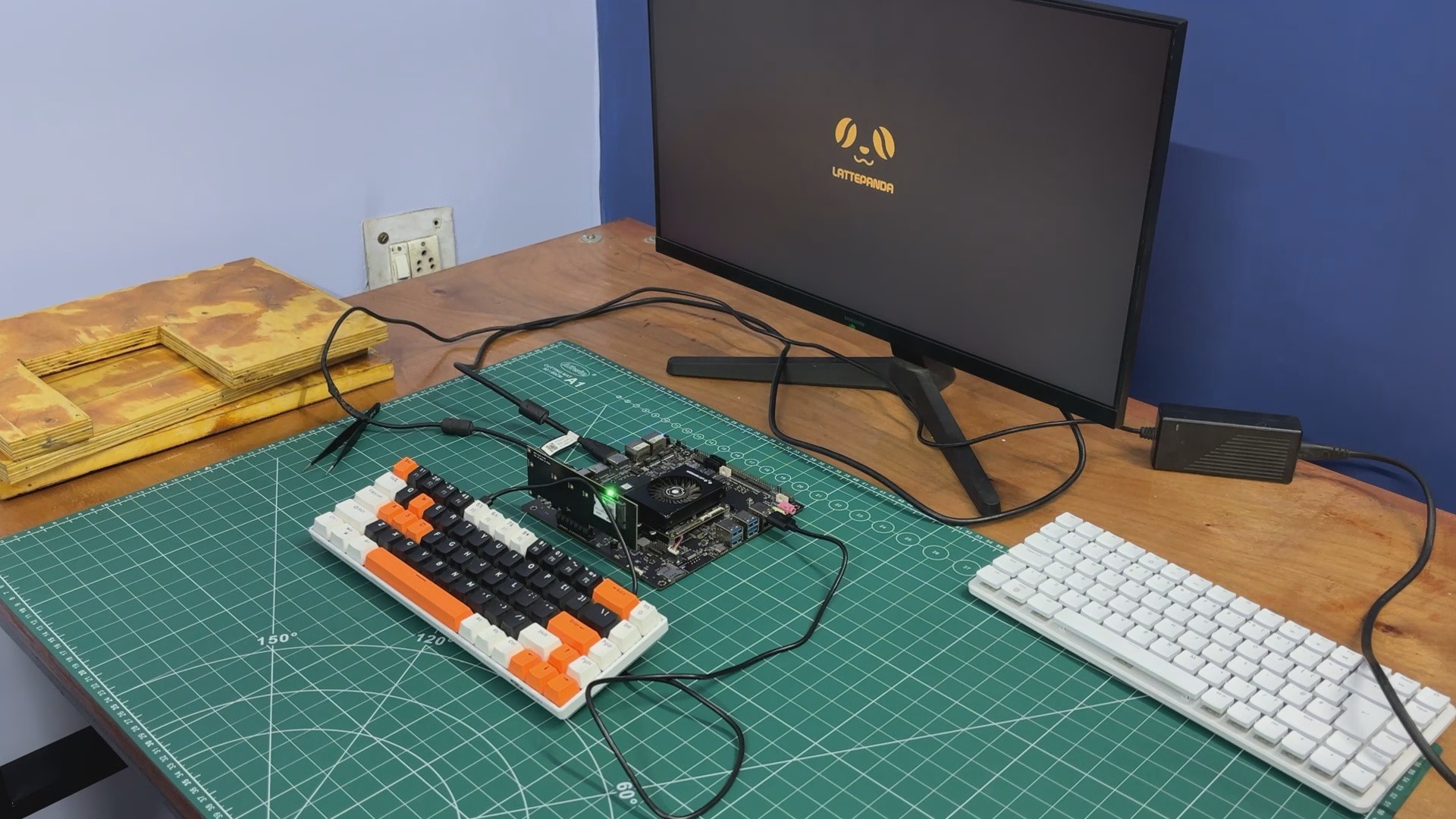
For the main computer in The Parallel Desk, we are using the LattePanda MU, powered by the Intel Core i3-N305 processor.
The LattePanda MU is a compact, SO-DIMM–style compute module that integrates a full x86 PC onto a small form factor. At its core is the Intel Core i3-N305, an 8-core processor based on Intel’s Gracemont architecture, designed for high efficiency while still delivering solid desktop-class performance. This makes it well suited for light gaming, emulation, media playback, and general desktop workloads.
The module comes with 16 GB of LPDDR5 memory onboard, providing high bandwidth and low power consumption, along with onboard NVMe storage, eliminating the need for external SATA or USB boot devices. Graphics are handled by Intel UHD Graphics, which supports modern display standards and hardware-accelerated media decoding. Despite its small size, the MU is essentially a complete PC, requiring only power, I/O, and display connections to function.
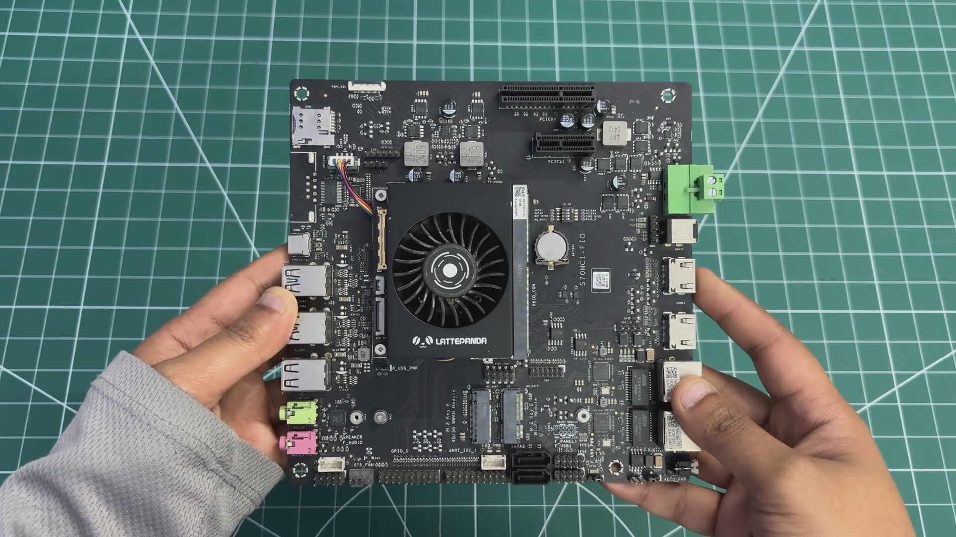
One of the most interesting aspects of the LattePanda MU is its modular design. Instead of building around a traditional motherboard, the compute module simply plugs into a carrier or evaluation board—much like laptop RAM—making system integration clean and flexible.
To make the MU usable as a full desktop system, we paired it with the LattePanda MU Full Evaluation Board, which acts as a carrier and breakout platform for all of the module’s interfaces.
The evaluation board exposes standard PC I/O, including multiple USB ports, full-size HDMI and DisplayPort outputs, Gigabit Ethernet, and audio I/O, allowing the MU to be used like a conventional desktop computer. It also provides PCIe expansion, enabling support for high-speed peripherals such as NVMe SSDs, network cards, or other PCIe devices.
The LattePanda MU was chosen because it brings true x86 performance into a very small footprint. Paired with the full evaluation board, it behaves like a traditional desktop PC while remaining compact enough to coexist with a Raspberry Pi Compute Module inside the same enclosure.
Check out one of my previous LattePanda MU-based projects.
https://www.hackster.io/Arnov_Sharma_makes/the-pvm-panda-69cdfa
RASPBERRY PI CM5 SETUP
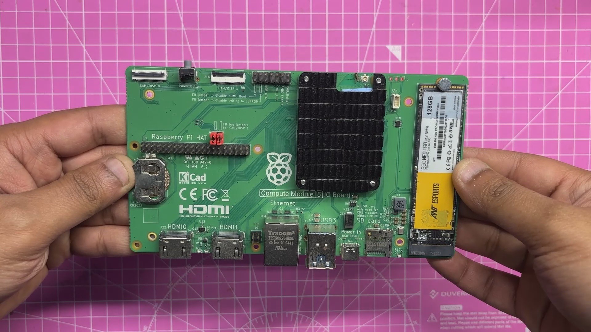
The second single-board computer used in this project is the Raspberry Pi Compute Module 5. It is powered by the Broadcom BCM2712 quad-core 64-bit Arm Cortex-A76 processor running at 2.4 GHz, offering a significant performance improvement over previous Compute Module generations. The module is available with LPDDR4-4267 SDRAM in 2 GB, 4 GB, 8 GB, and 16 GB variants, all supporting error correction. Storage options include a Lite version with no onboard storage, as well as eMMC capacities of 16 GB, 32 GB, and 64 GB.
For connectivity, the Compute Module 5 supports dual-band Wi-Fi (2.4 GHz and 5 GHz) with IEEE 802.11 b/g/n/ac, Bluetooth 5.0 with BLE, and a Gigabit Ethernet PHY with IEEE 1588 support. Expansion and interfacing options include PCIe Gen 2 with a single x1 root complex at 5 Gbps, USB 3.0 and USB 2.0, and up to 30 configurable GPIO pins operating at 1.8 V or 3.3 V. Additional interfaces such as UART, I2C, SPI, SDIO, DPI (RGB display), I2S, PWM, and GPCLK make the module highly flexible for embedded applications.
In terms of multimedia capabilities, the Compute Module 5 provides two HDMI 2.0 outputs capable of 4K 60 fps, along with two four-lane MIPI connectors for camera and display connectivity. Graphics support includes a 4K 60 fps HEVC decoder, OpenGL ES 3.1, and Vulkan 1.2. Power is supplied through a single 5 V input with USB Power Delivery support, allowing a current draw of up to 5 A. With an operating temperature range of −20°C to +85°C, the module is well-suited for long-term and industrial deployments.
Unlike standard Raspberry Pi boards, the Compute Module 5 does not include onboard USB, HDMI, or Ethernet connectors. Instead, these interfaces are exposed through high-density edge connectors, allowing the module to be used with an evaluation board or a custom carrier board.
The official Compute Module 5 IO Board acts as a breakout platform, exposing all major interfaces of the module. It features a standard 40-pin GPIO header, two full-size HDMI 2.0 ports, two USB 3.0 ports, Gigabit Ethernet with PoE support, and an M.2 PCIe slot for expansion. It also includes two four-lane MIPI DSI/CSI-2 connectors for direct display and camera connections. The board is powered via USB-C, ensuring stable power delivery for high-performance use cases.
One of the main reasons for choosing the Compute Module 5 for this project is its NVMe support and dual full-size HDMI outputs, which make it ideal for Raspberry Pi–based development inside a custom PC enclosure. Since most of my projects are built around Raspberry Pi platforms, having a Compute Module inside this system was an essential design choice for future projects.
Check out a previous CM5-based project of mine.
https://www.hackster.io/Arnov_Sharma_makes/mac-pi-a48047
HDMI SPLITTER
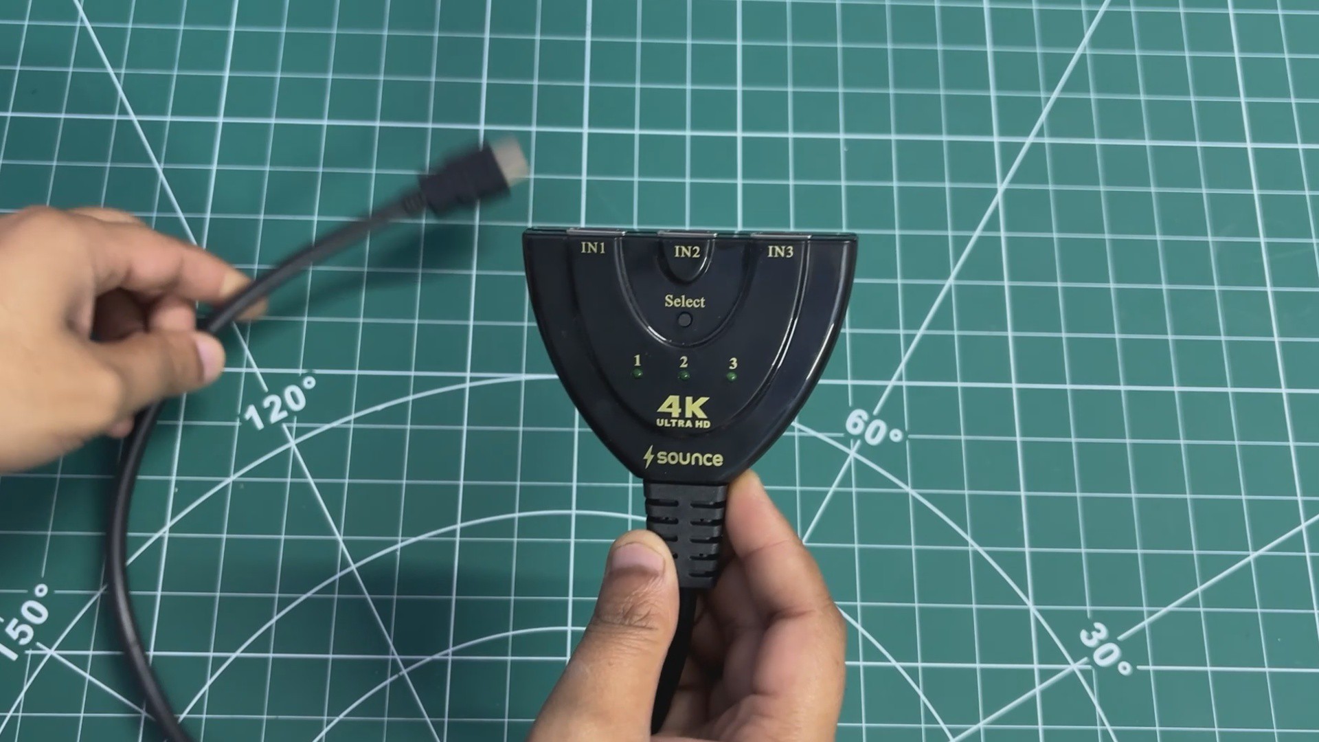
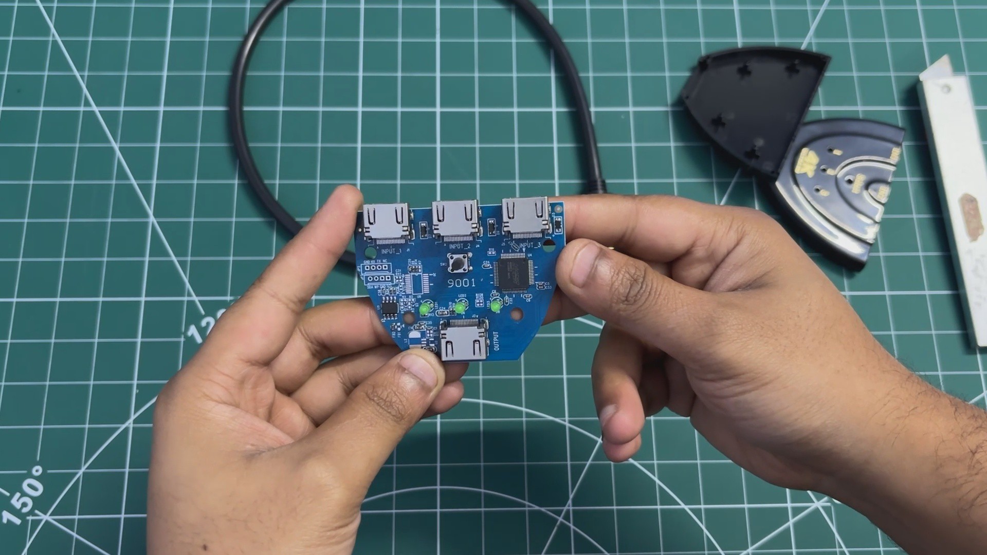
Our goal was to use a single LED display panel as the main display while running two SMPS units. Since only one SBC can drive the display at a time, an HDMI splitter became the obvious solution. We used a three-input, one-output HDMI splitter from Sounce. Opening it up was straightforward—the enclosure doesn’t use screws and is instead held together with snap locks. Using a prying tool, we were able to open the casing and access the circuit inside.
The board features proper HDMI connectors: one output port and three input ports. Each HDMI input has an associated LED indicator that lights up to show which input is currently selected. The main control element on the board is a push button, which allows us to switch the active input connected to the output.
DUAL SBC SAME DISPLAY SETUP

To test the HDMI splitter, we set up a minimal configuration using two SBCs. The HDMI output of the LattePanda was connected to the first HDMI input of the splitter, while the Raspberry Pi Compute Module was connected to the second HDMI input.
A monitor was connected to the HDMI output of the splitter. By default, the display shows the output from the first HDMI input. When the push button is pressed, the display output switches from the first SBC to the second.
UPDATED 3D DESIGN
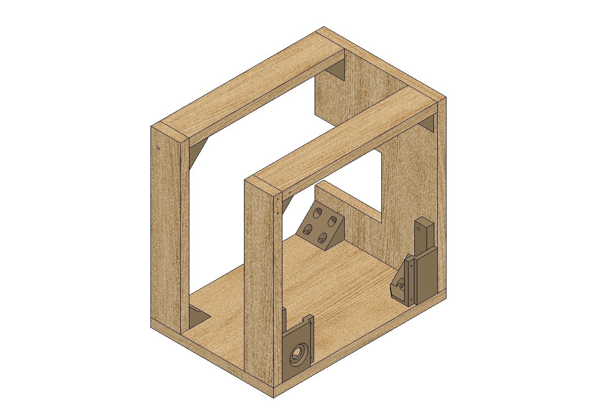
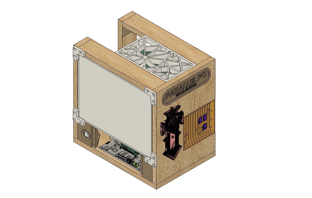
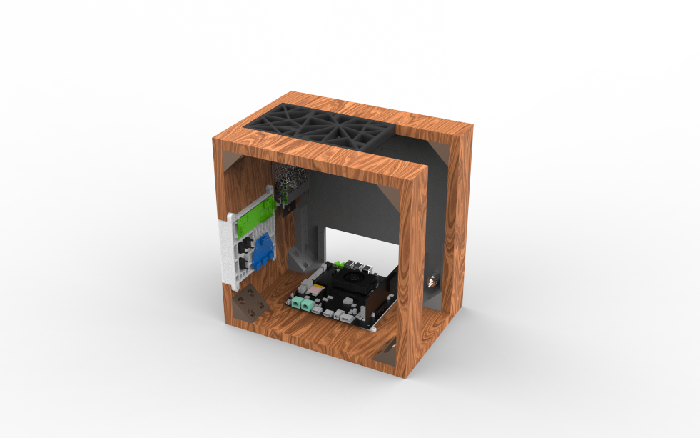

The 3D model for this project was created by reusing and modifying the model from our previous WoodWorks Fusion PC build. Reusing parts from the older project was one of the main goals, as we wanted to evolve the original design rather than start from scratch.
In the updated model, the old display was removed and replaced with a new LED panel. The new screen is slightly smaller and significantly thinner than the previous LCD monitor, which required changes to the overall size of the wooden frame and panels. Along with this, the display holder and the front screen mount were also redesigned.
The original motherboard, power supply, and internal hardware were completely removed, leaving the model empty before adding the new components. We then integrated the 3D model of the LattePanda MU expansion board into the frame. The SMPS power supply was also modeled and positioned on the side wooden panel, slightly above the grill area.
The grill section itself was redesigned and now serves as a mounting point for both the HDMI splitter and the display driver board. On the top side, a mesh-style component was modeled, which also functions as the holder for the Raspberry Pi Compute Module.
Finally, a panel-mounted push button was added to the front of the model, which will be used to control the HDMI splitter output.
Below are the 3D model parts we used in this project and their details.
- L Bracket with four Holes—a total of six of them are required, and they will be printed using brown PLA with 25% infill. These L brackets were the only things we reused from the previous woodwork fusion PC project.
- L Bracket Long Version—This will be used to hold the display in place, and we need two of them with the same print settings and 25% infill.
- Lattepanda MU Holder—The MU Holder was printed in White Hyper PLA, with an infill of 50%.
- Screen Holder Front—four pieces were printed with Black Hyper PLA with 50% infill each.
- Raspberry Pi CM5 board Frame/Grill—This grill-holder part was printed in Hyper Black PLA with an infill of 30%.
- SIDE GRILL—This part was printed with White Hyper PLA.
- Display Holder—We printed this part (two holders) with grey PLA with an infill of 25%.
- Nametag—We printed this part with white Hyper PLA with an infill of 25%.
This is link for 3D MODEL https://a360.co/3MQalQh
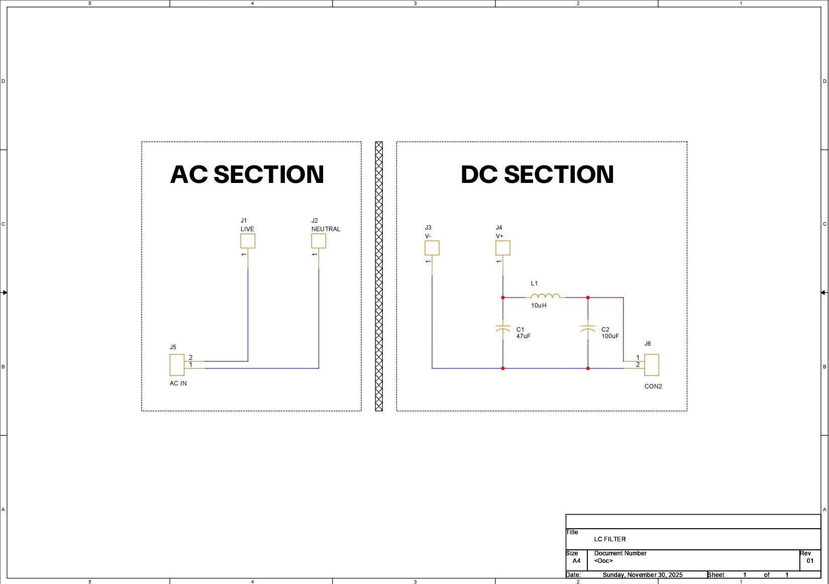
PCB DESIGN- LC FILTER


In our project, we wanted to use a 12 V, 5 A SMPS, which may or may not have voltage ripple at its output. These SMPS units are generally fine for driving MCUs, relay boards, motors, and other crude electronics, but something more sensitive—like an SBC or a display—can get affected by the ripple and noise generated by these supplies.
One option would be to use a well-branded SMPS, such as ones made by Mean Well or Honeywell, but those supplies are expensive. Also, in the local market, it is common to find power supplies that claim to be from these brands but may actually be knockoffs. Because of this, our approach was to improve the output quality of the SMPS by adding an LC filter circuit on the output side.
The LC filter is implemented by connecting a 10 µH inductor in series with the positive output line. On both sides of the inductor, decoupling capacitors are connected between the supply rail and ground, forming a C–L–C (π-filter) configuration. The capacitor placed before the inductor helps absorb high-frequency switching noise coming directly from the SMPS, while the capacitor placed after the inductor smooths the remaining ripple and provides a more stable voltage to the load.
At the input side of the filter, we used a 47 µF, 100 V capacitor, and at the output side, we used a 100 µF, 63 V capacitor. This simple LC filter significantly improves the DC output quality of the SMPS, making it suitable for powering sensitive loads like SBCs and displays.
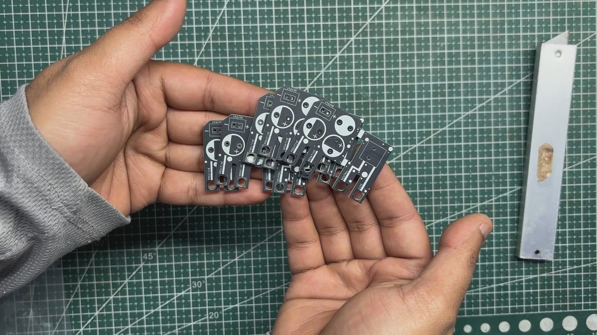
After preparing the schematic, we started the PCB design process. The board outline was taken directly from the CAD model prepared earlier and used as the main PCB outline. The AC terminal was placed close to the AC input side, and the C–L–C filter configuration was placed near the DC output side to keep the power path short and clean.
The mounting holes on the PCB are plated, so when the PCB is mounted onto the SMPS using bolts, the PCB makes a secure electrical and mechanical connection with the SMPS terminals. This ensures a reliable connection between the SMPS and the filter PCB.
PCBWAY SERVICE
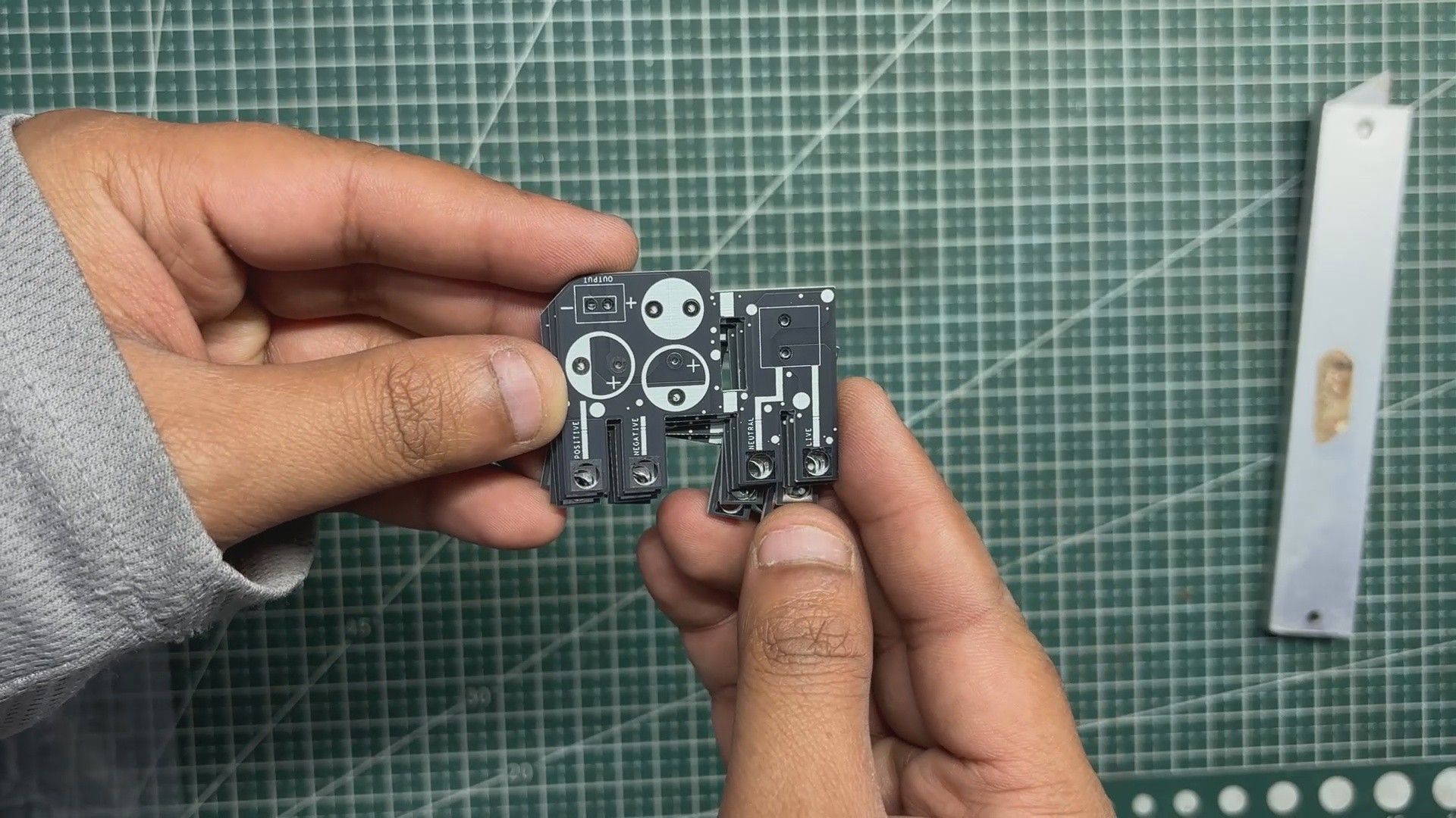
After finalizing the PCB design, we exported the Gerber files and uploaded them to the quote page on PCBWay. For this project, we chose a matte black solder mask with white silkscreen.
The PCBs were delivered within a week, and the quality was excellent, as always. While I usually stick to white or standard black solder masks for most of my builds, this time I decided to try PCBWay’s matte black finish. This was partly inspired by their Christmas sale campaign, during which matte black, purple, and pink solder mask options were available for a limited time. The matte black finish added a subtle, premium look that fit the project perfectly.
Over the past ten years, PCBWay has distinguished themselves by providing outstanding PCB manufacturing and assembly services, becoming a trusted partner for countless engineers and designers worldwide.
Also, PCBWay is organizing the PCBWay 8th Project Design Contest, a global event that invites makers, engineers, and innovators to showcase their most creative builds. With categories in Electronics, Mechanical, and AIoT, it’s a great opportunity to share your work, connect with the community, and compete for exciting prizes.
You guys can check out PCBWAY if you want great PCB service at an affordable rate.