Arnov Sharma
Greetings, everyone, and welcome back. This one’s a big build—meet the Parallel PC.

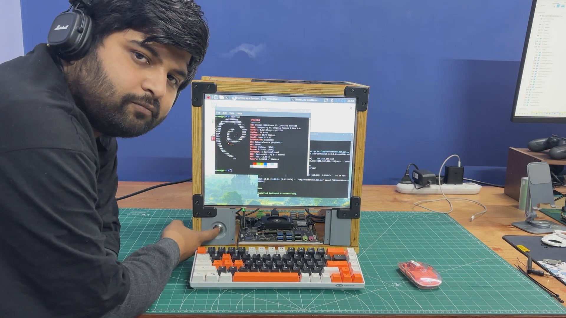
Parallel PC is a DIY all-in-one computer featuring a custom body made from wooden panels and 3D-printed parts, built around a 15-inch LED display. What makes it special is that it houses not one but two different single-board computers. One is the ARM-based Raspberry Pi Compute Module 5 with its official evaluation board, and the other is an x86-based LattePanda MU.
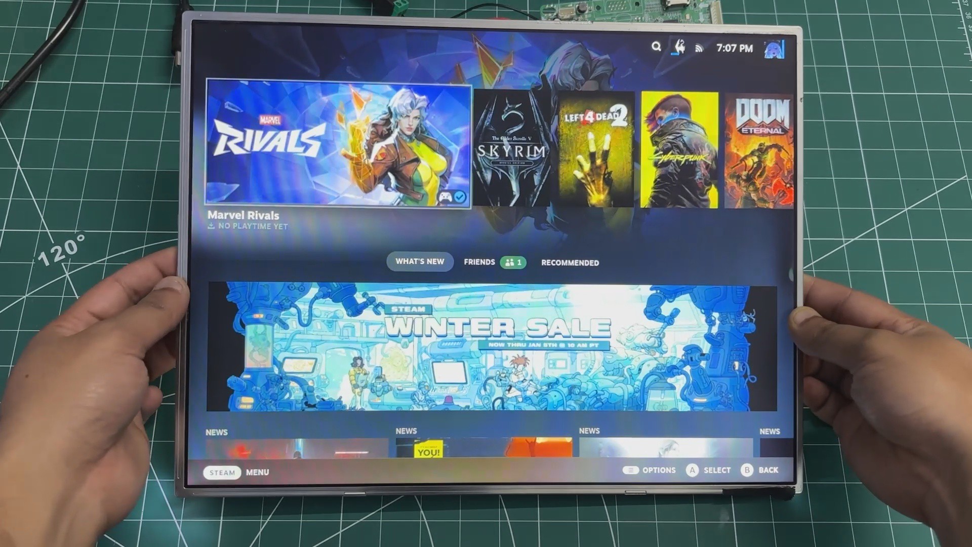
The idea behind this project was to take one of my previous builds—the WoodWorks Fusion PC—and transform it into a dual-compute system. With the press of a single button, the active computer connected to the main display can be switched instantly. If you want to work on Raspberry Pi projects, you switch to the Pi. If you need an x86 environment to run Windows or, in our case, Bazzite, you switch over to the LattePanda. One enclosure, one monitor, two completely different computing platforms.
Built using a combination of wooden panels and custom 3D-printed parts, this project is the starting point of the Parallel PC series. The goal is to keep evolving this enclosure—retrofitting new hardware, adding more single-board computers, and experimenting with different ideas over time.
This article covers the complete build process of the Parallel PC, from design to final assembly. Let’s get started with the build.
MATERIALS REQUIRED
These were the materials we used in this build:
- Custom PCBs (provided by PCBWAY)
- Woodwork Fusion PC Body (that includes all the wooden parts)
- Raspberry Pi CM5 with expansion board
- Type C to C PD Cable
- Lattepanda MU with Full Evaluation Board
- HDMI Splitter
- 15-inch LED Display along with its Driver (Salvaged from a new monitor)
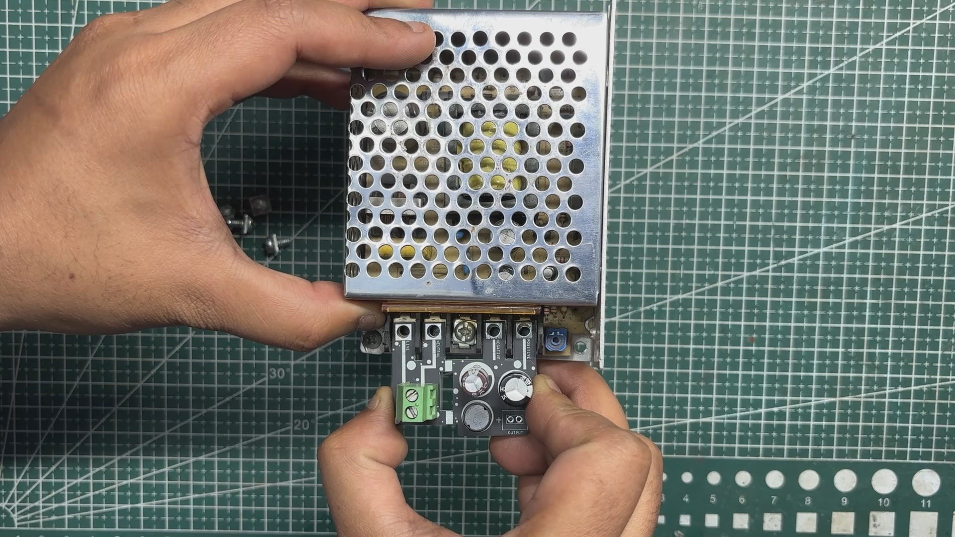
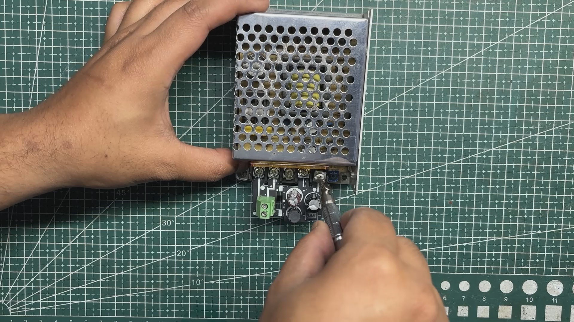
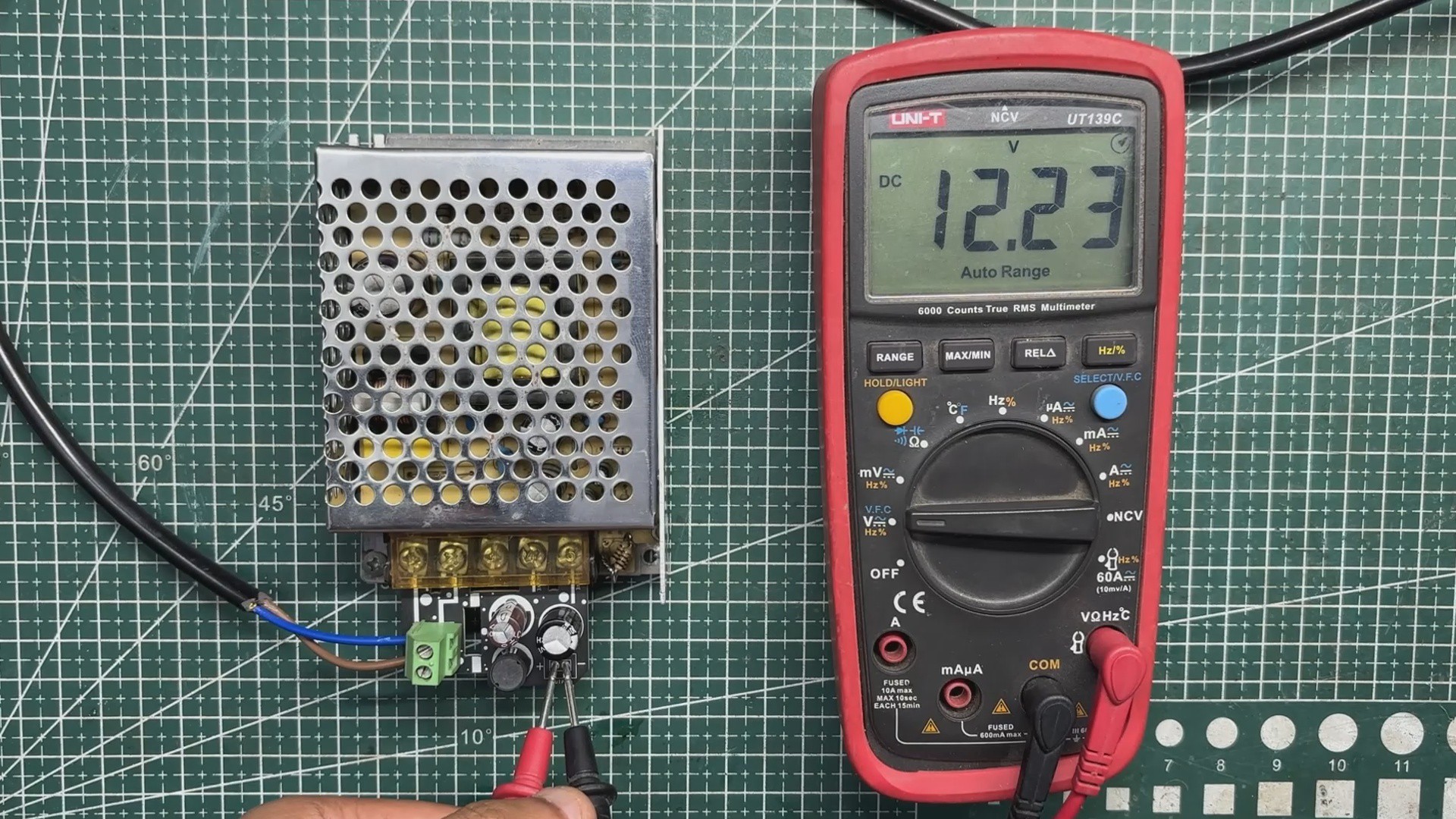
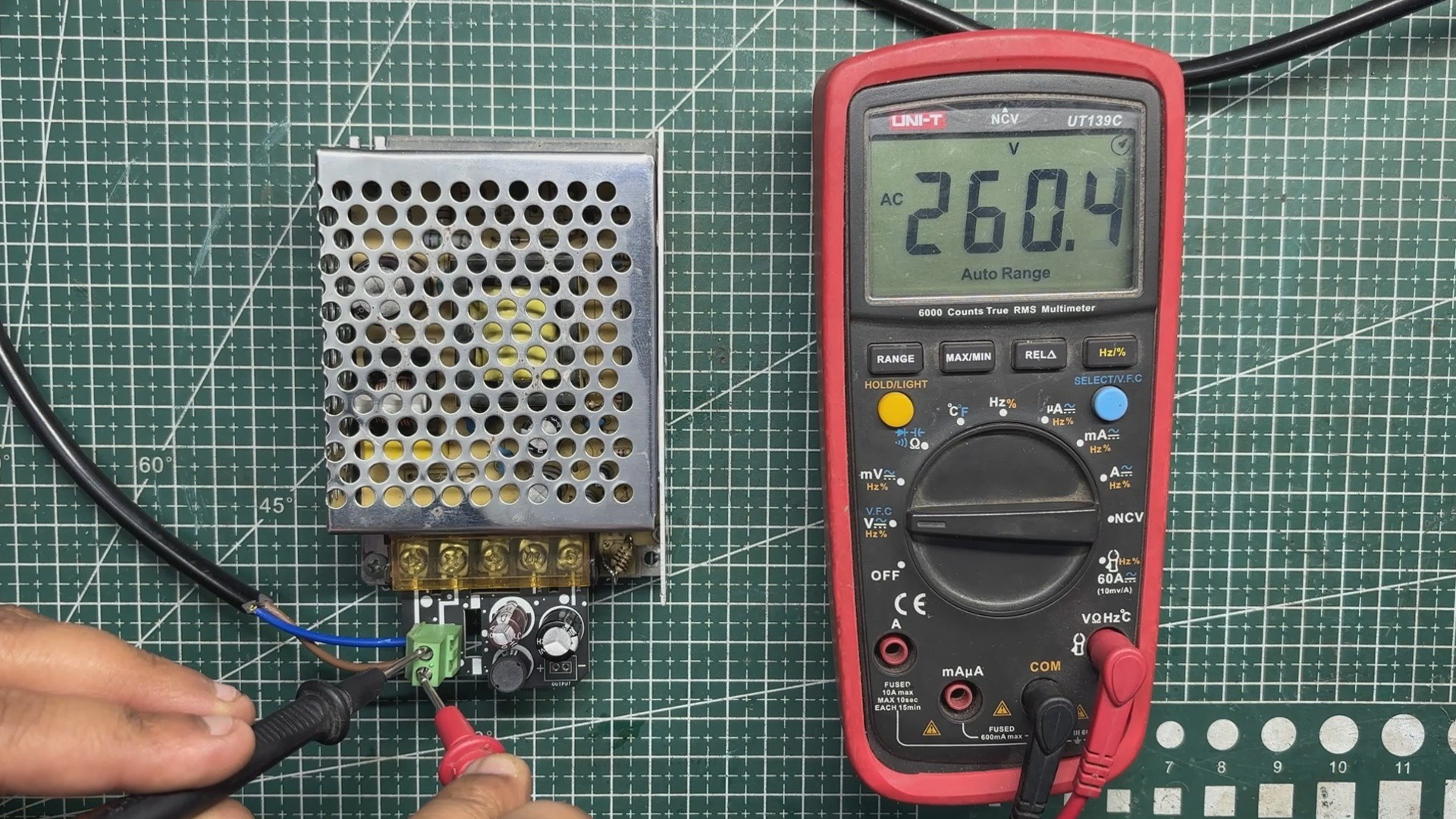
- 12V 5A Mini SMPS
- Wood screws M4
- 3D-printed parts
- PD Buck Converter
- HDMI CABLE 0.5 METER
- HDMI BREAKOUT BOARD WITH FLAT CABLE
- M2 SCREWS
Woodwork Fusion PC

The original WoodWorks Fusion PCwas a custom all-in-one computer built from scratch using a combination of wood and 3D-printed parts, inspired by CyberDesk-style aesthetics.
The goal was not performance but form—creating a visually striking enclosure around deliberately outdated hardware, basically a potato PC.
At its core, the system used a 4th-generation Intel i3 desktop CPU mounted on a Mini-ATX motherboard, paired with 12 GB of DDR3 RAM and a GT 710 GPU. While the hardware was clearly obsolete, the enclosure was designed to be modular, allowing components to be easily upgraded in the future without changing the overall structure.
The body was primarily constructed from plywood, chosen for its strength and ease of fabrication. 3D-printed L-brackets were used to join panels together, forming a rigid cuboid enclosure capable of housing the motherboard, power supply, storage drives, and display.
DISPLAY


In the previous version of this project, we reused an old LCD monitor from around 2012. It was a Samsung 4:3 display, a format that was very common during the early days of LCD screens.
At the time, most content and applications were designed around this aspect ratio. As display technology evolved, wider screens became the standard, driven by changes in content consumption, improved productivity workflows, and the demand for more immersive experiences in multimedia, professional work, and gaming.
For this revised build, we switched to a much slimmer 15-inch LED display, salvaged from a low-cost monitor purchased for under $25.
We stripped down a low-cost monitor and reused its TFT panel for this project. The monitor’s HDMI driver board was retained, but its original power supply was intentionally omitted. Instead, the display is powered by the same SMPS used for the other internal components. This approach helped reduce the overall size of the wooden frame, making the final build more compact.
LATTEPANDA MU FULL EVALUATION BOARD SETUP
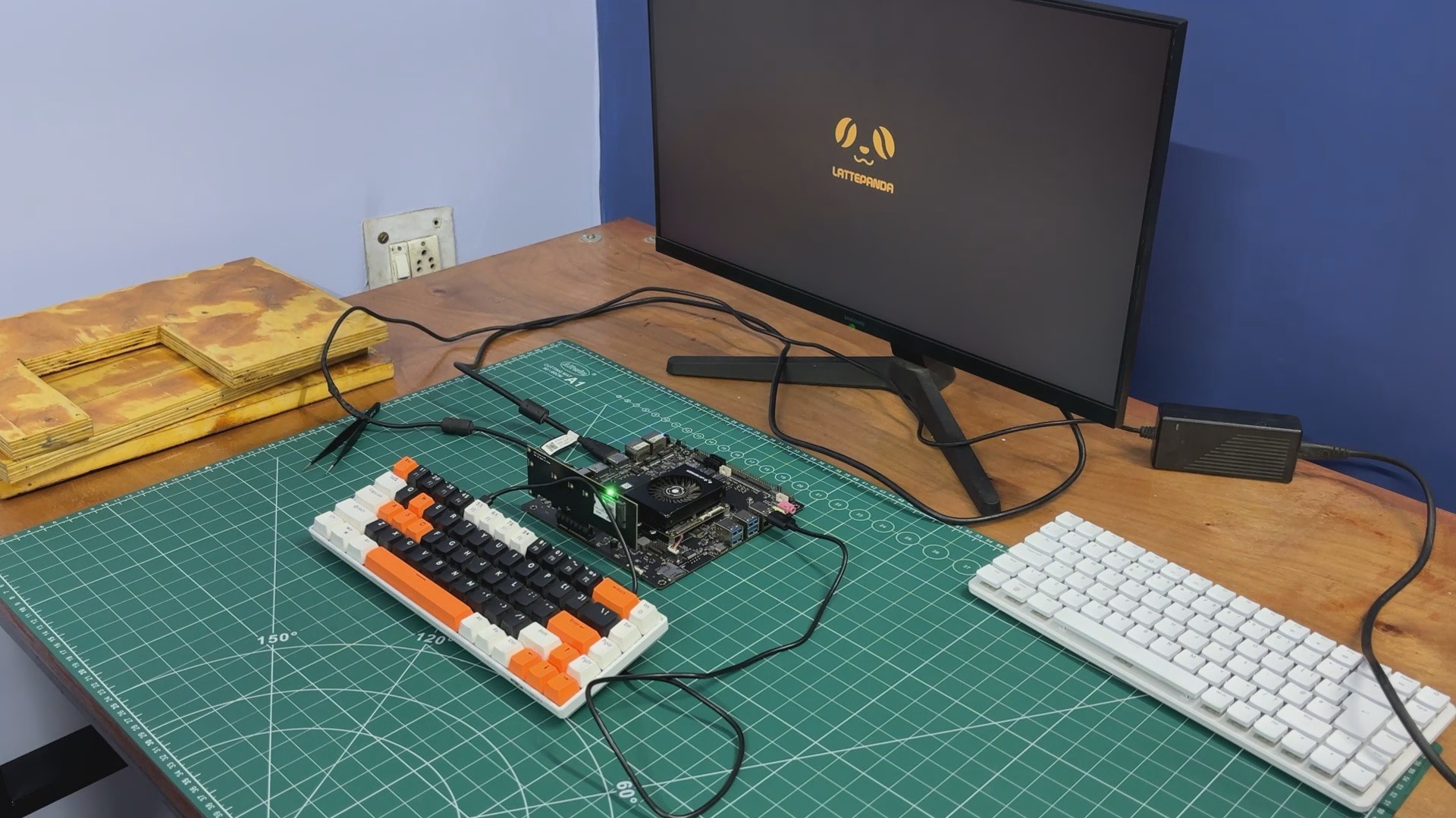
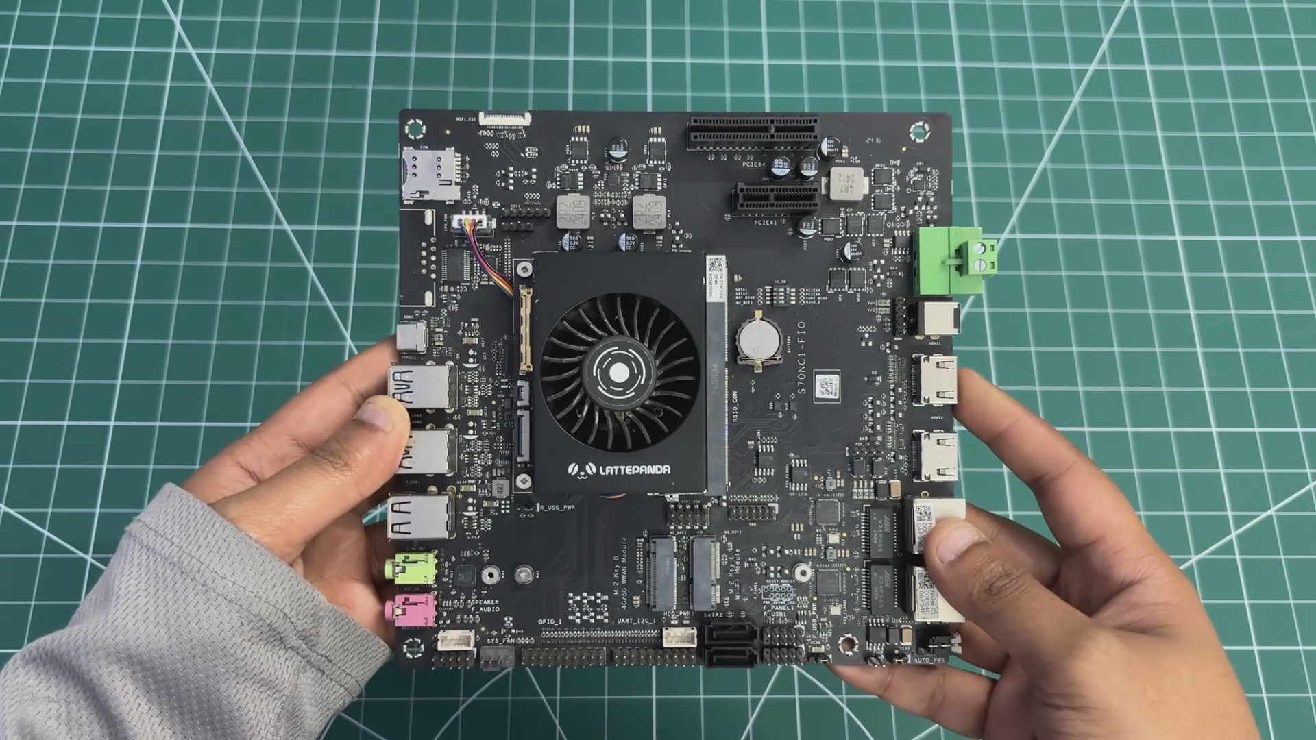
For the main computer in The Parallel Desk, we are using the LattePanda MU, powered by the Intel Core i3-N305 processor.
The LattePanda MU is a...
Read more »


 rob
rob