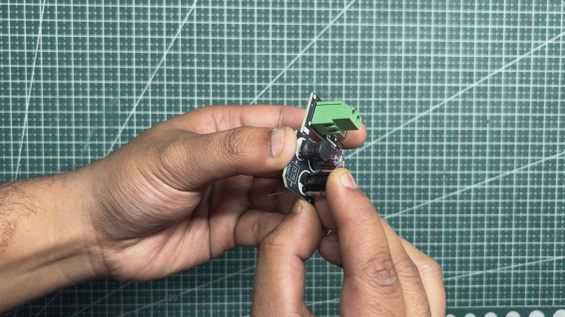
The filter circuit was assembled using only through-hole components. Assembly began with the placement of the CON2 screw terminal, followed by the 10 µH inductor.
Next, the input-side capacitor was installed, followed by the output capacitor.
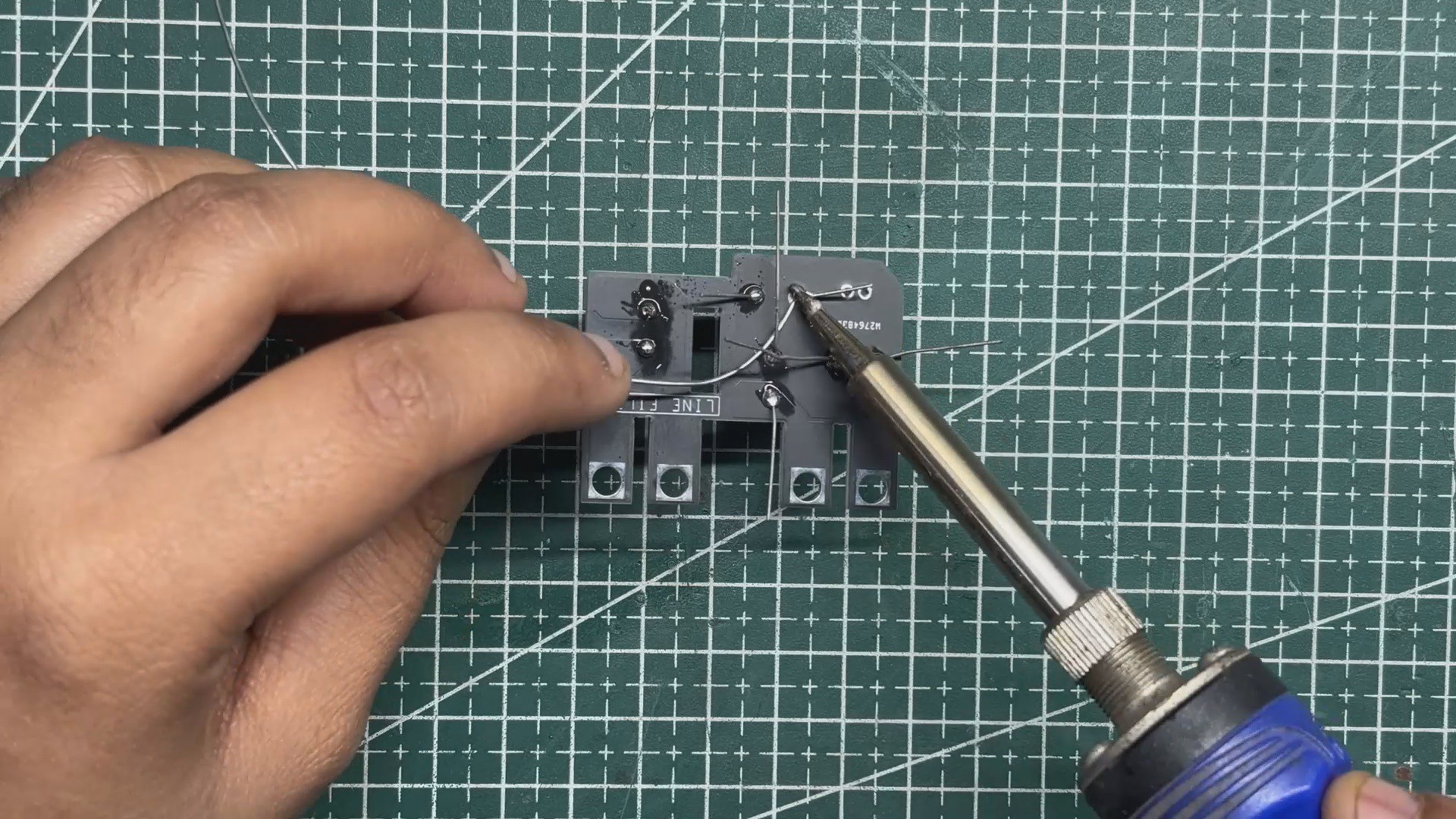
Once all components were placed, the board was flipped over and the leads were soldered using a soldering iron.
After soldering, the excess lead length was trimmed using a nipper plier to complete the assembly.
2
FILTER CIRCUIT & SMPS ASSEMBLY
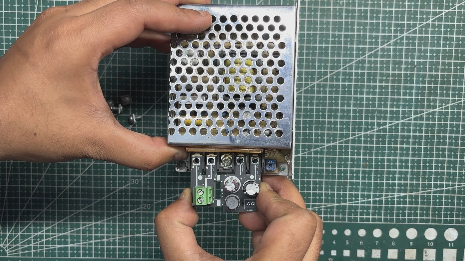
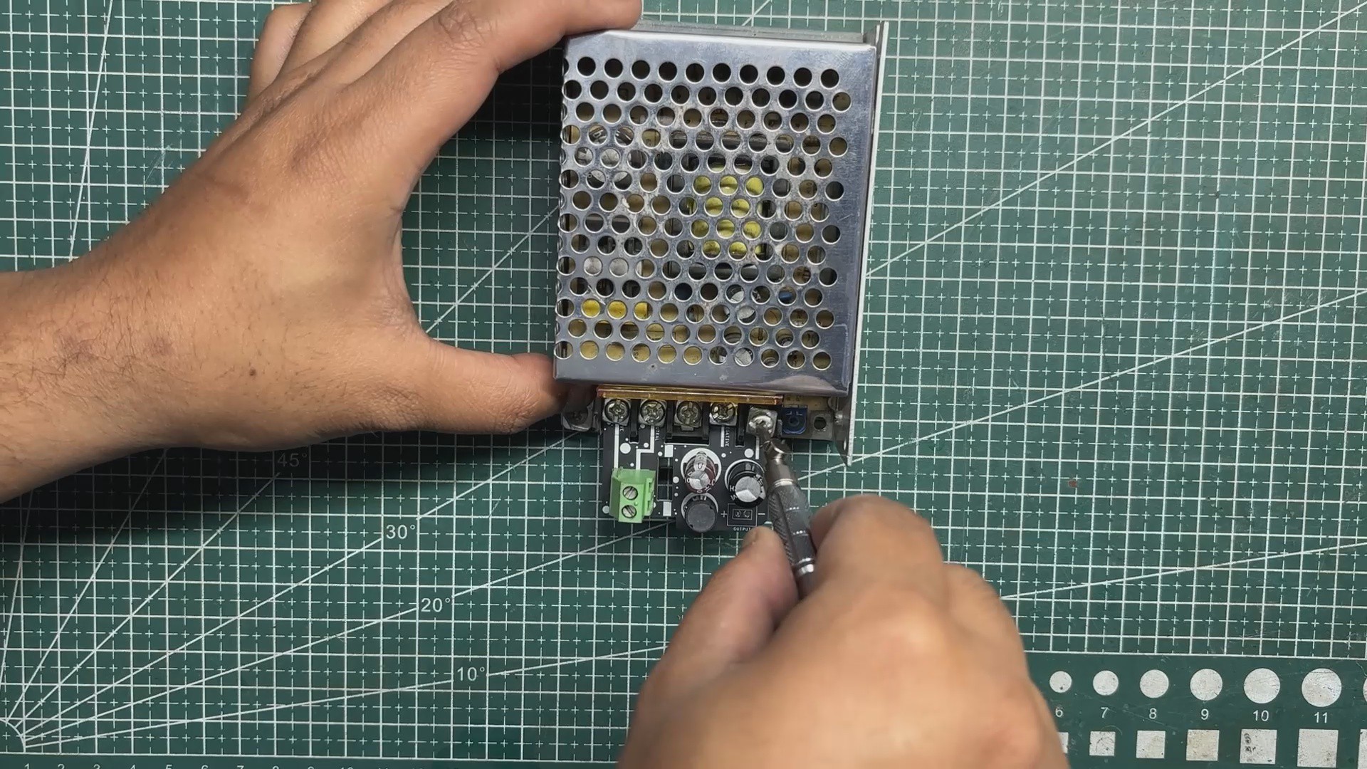
The assembled filter circuit was positioned over the mounting holes of the SMPS, ensuring that the PCB was properly aligned.
Four mounting screws were then used to secure the board firmly in place, allowing the PCB traces to interface cleanly with the SMPS connections.
Next, a power cord was connected to the SMPS by wiring the live and neutral lines of the mains cable to the CON2 screw terminal on the filter circuit.
3
FILTER CIRCUIT TEST
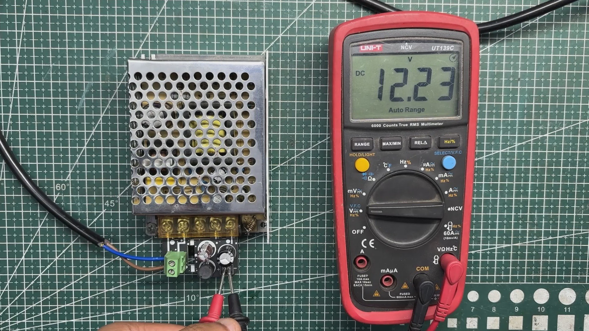
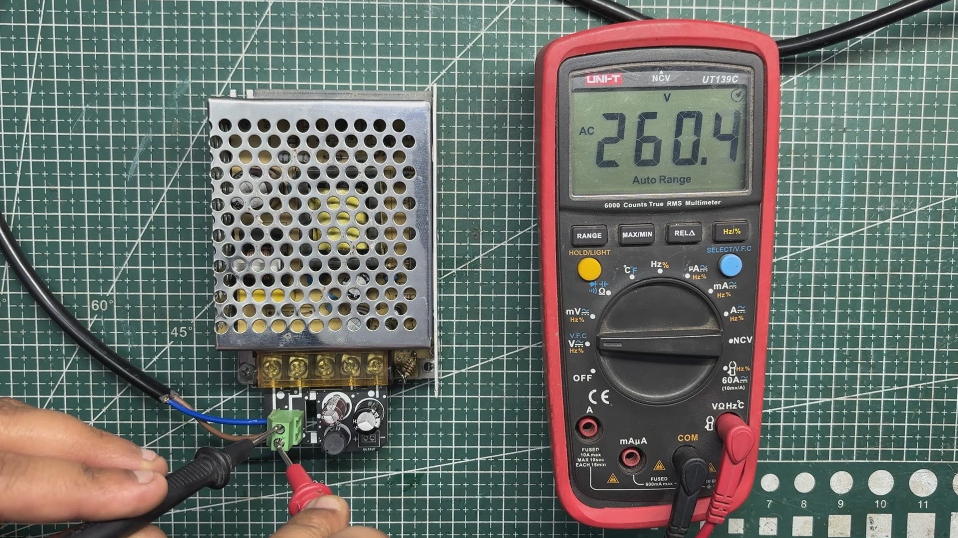
We first plugged the AC cord into the mains socket and measured the input voltage, which was around 260 V AC. Next, we measured the voltage at the output of the filter circuit and obtained a stable 12.2 V DC. This stable output is achieved by adding our LC filter at the SMPS output, which helps suppress switching noise and smooth out voltage ripple.
To verify the effectiveness of the filter, we measured the output using an oscilloscope. The scope showed a ripple of approximately 40 mV peak-to-peak, indicating that the high-frequency noise from the SMPS has been significantly attenuated. This level of ripple is well within acceptable limits and is well-suited for our SBC and display loads.
4
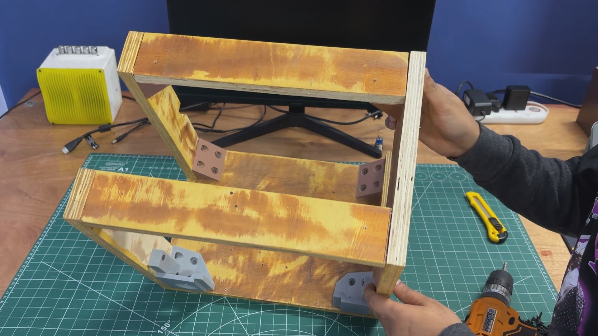
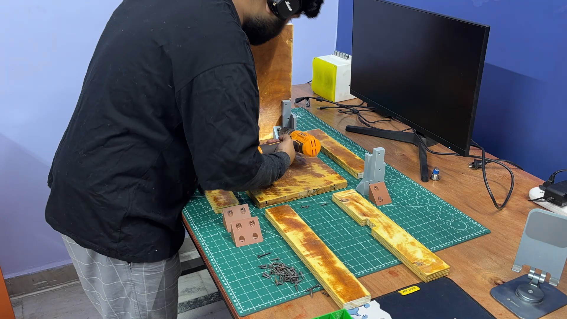
PARALLEL PC WOODEN ENCLOSURE ASSEMBLY
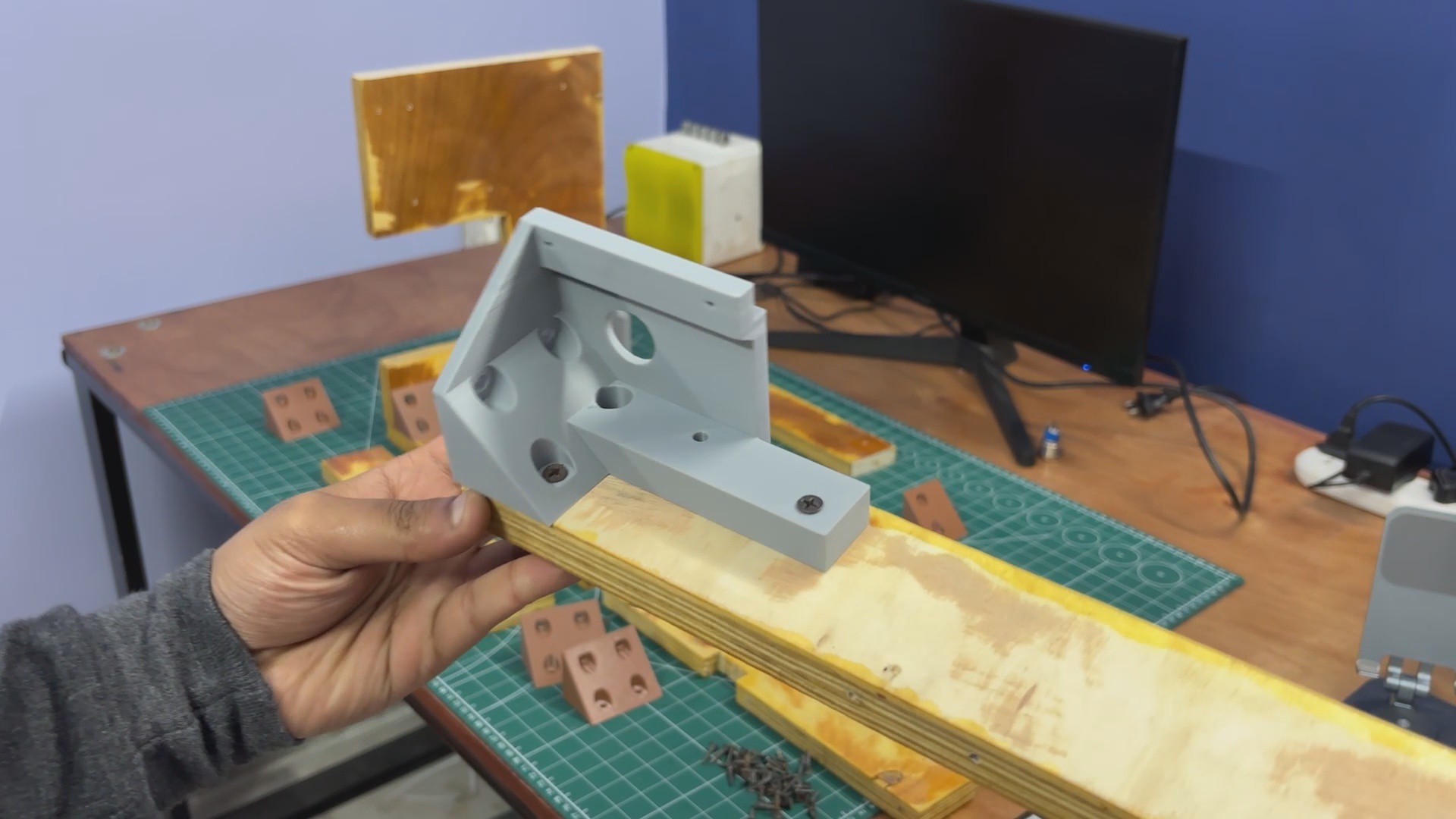
As mentioned earlier in the build log, we followed the assembly sequence defined in the 3D model. We started by attaching the right-side panel to the base using L-brackets and one of the display holder brackets. These were secured using M4 wood screws, and an electric screwdriver–drill combo was used to speed up the process.
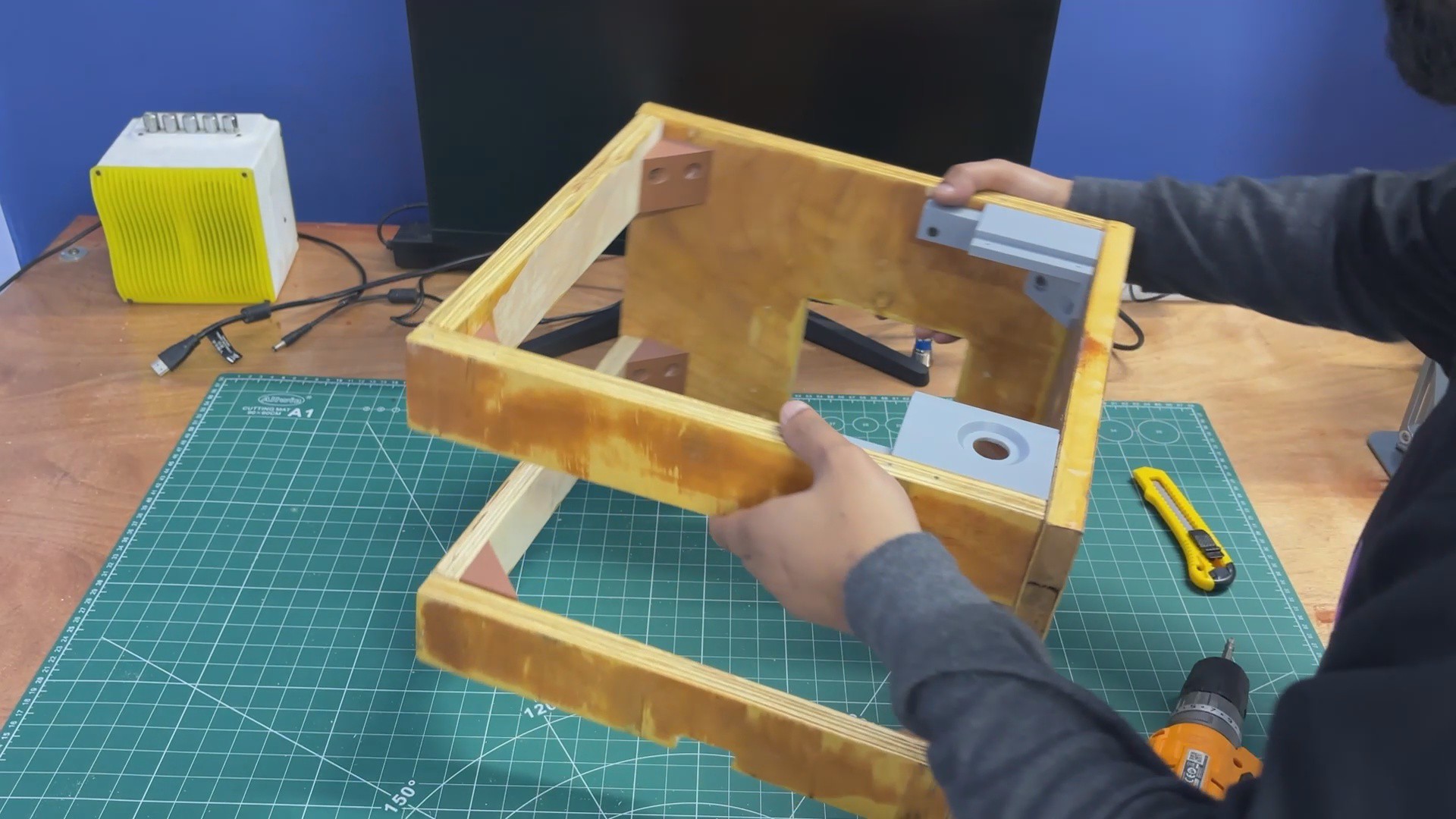
Next, the left-side panel was added and fixed in place using two additional L-brackets.
After that, four L-brackets were mounted on the top side panels—two per panel.
The top panel was then positioned and secured to both the left and right side panels.
The result of this process is a rigid wooden frame assembly that serves as the main enclosure for the PC.
5
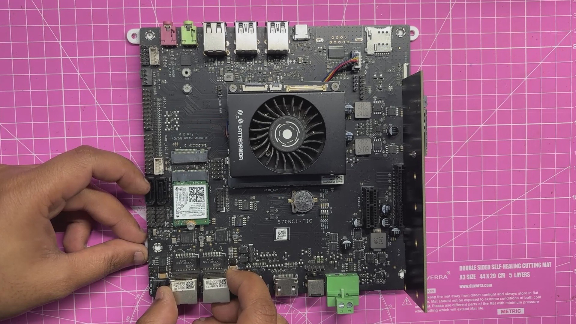
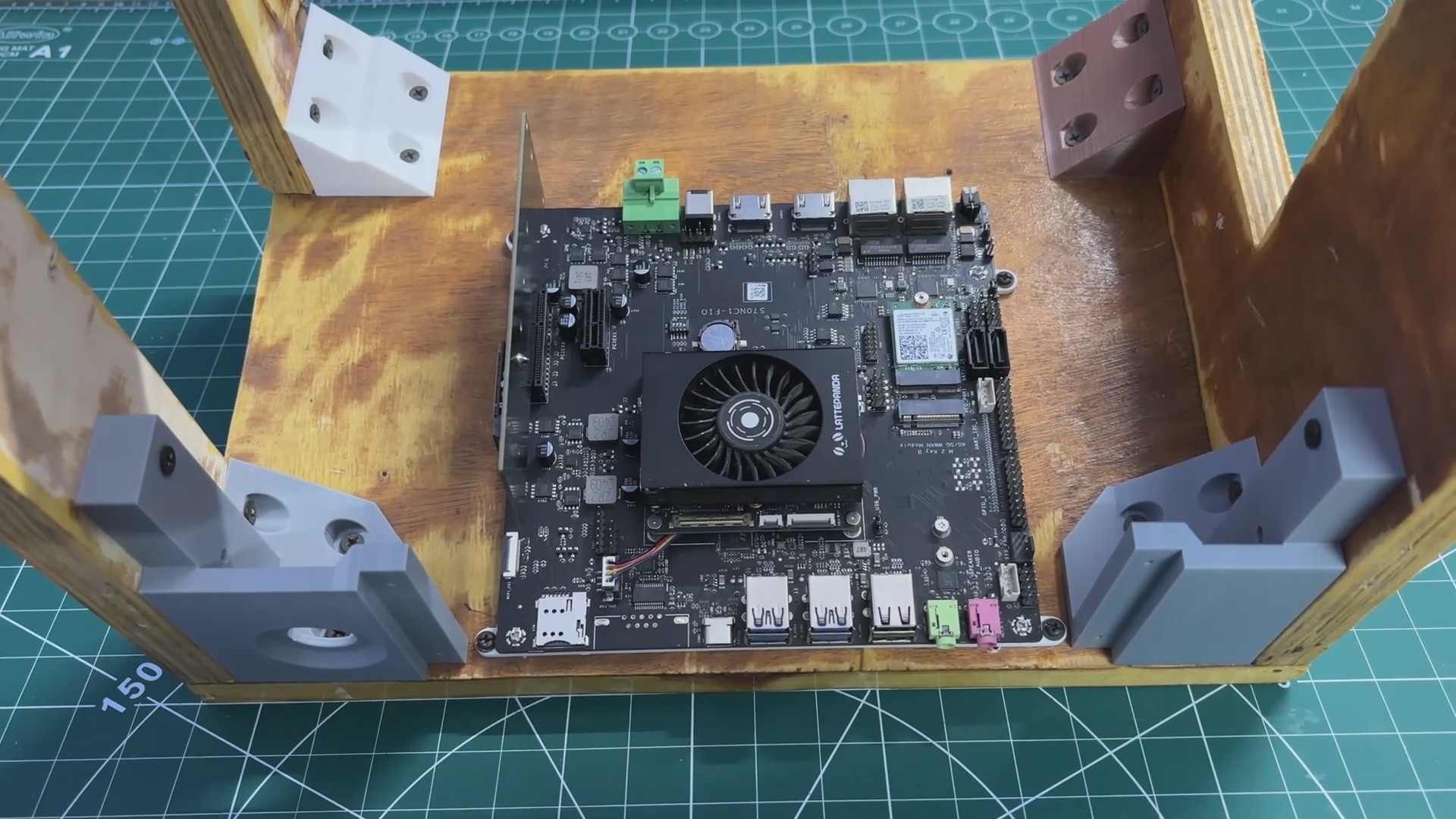
LATTEPANDA MU HOLDER
The MU holder assembly process was straightforward.
The LattePanda MU full evaluation board was placed onto the 3D-printed holder, ensuring that all mounting holes were properly aligned.
Four M2 screws were then used to secure the evaluation board to the holder.
Before mounting, the PCIe-to-M.2 adapter card was temporarily removed, as it obstructed one of the mounting holes.
Once the evaluation board and 3D-printed holder were securely fastened, the PCIe-to-M.2 adapter was reinstalled into the PCIe slot.
6
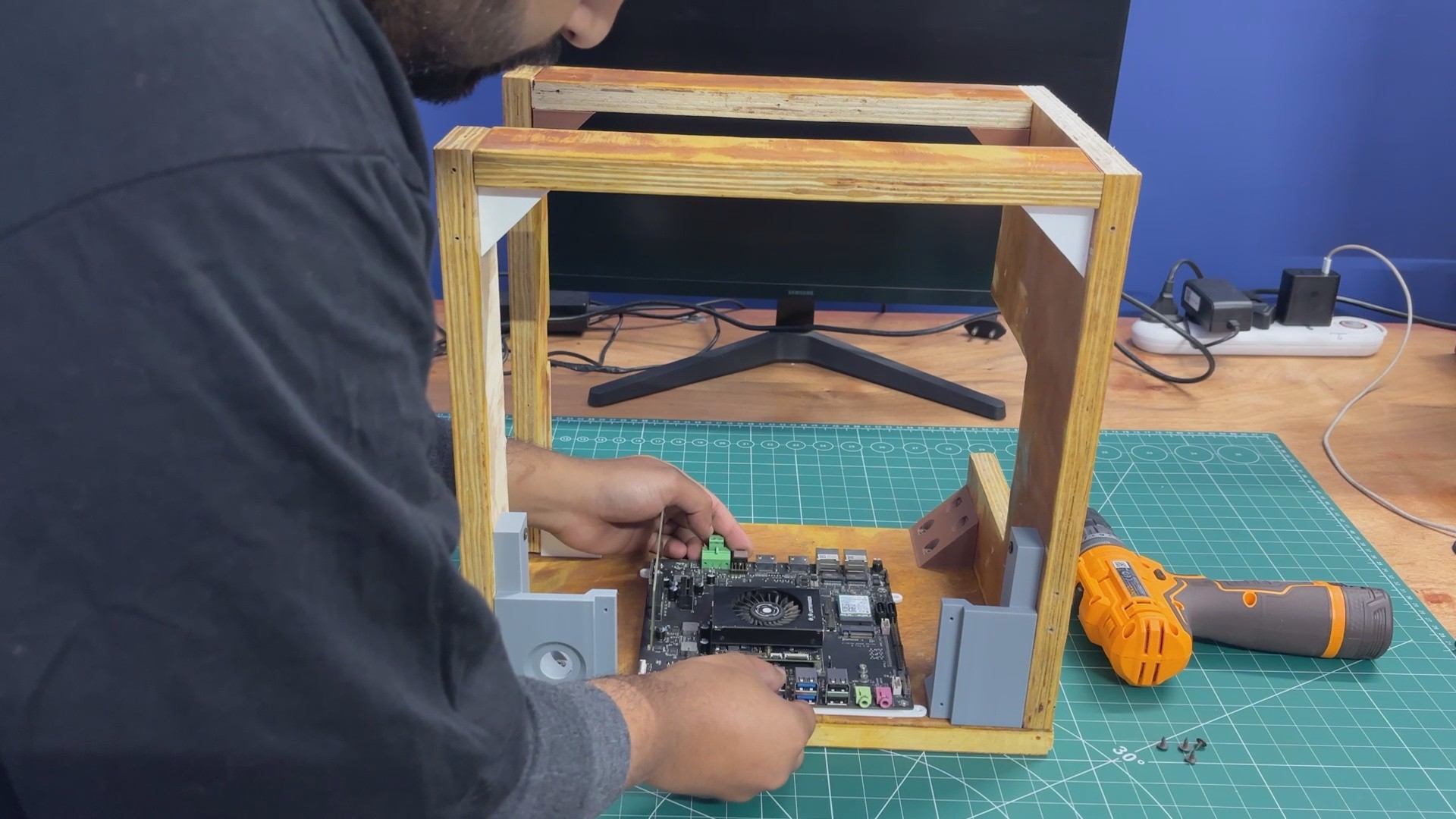
LATTEPANDA MU WITH FRAME ASSSEMBLY
We placed the LattePanda MU holder in its position as defined in the CAD model. Next, we used four M3 screws to secure it to the wooden base, making sure that the USB port side was oriented toward the front of the enclosure
7
FRONT SWITCH ASSEMBLY
We began the front switch assembly by desoldering the existing switch wires. The switch was then passed through the hole provided in the front display holder. Since it is a panel-mount push button with a nut-and-bolt-style design, it was secured in place by tightening the nut.
After mounting the switch, the wires were resoldered to the switch terminals, completing the assembly. The HDMI output can now be controlled directly using the front-mounted button.
8
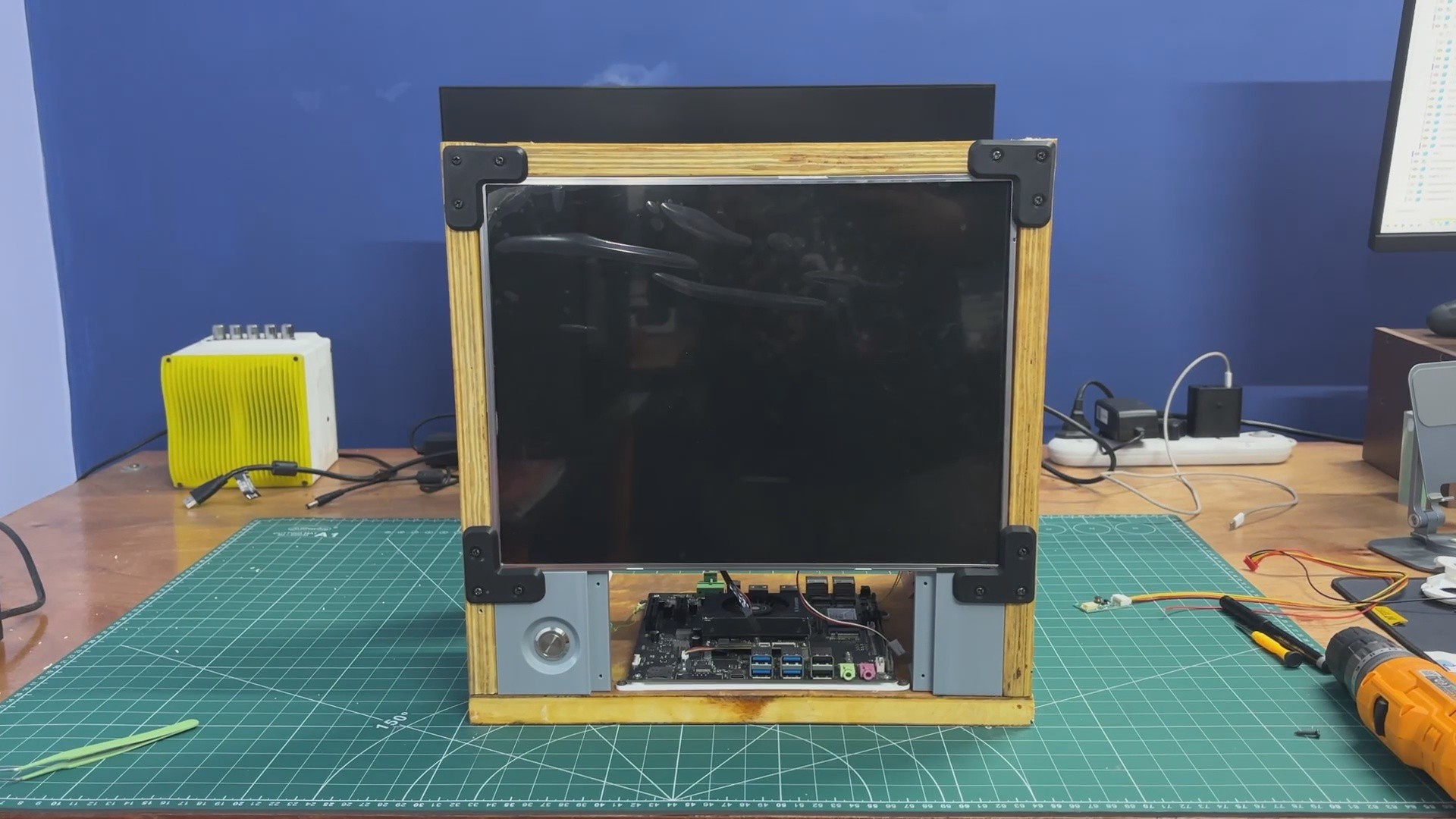
LED DISPLAY FRAME ASSEMBLY
The display was installed from the front side and positioned in place. It was then secured using four screen holders, with one holder attached at each corner to lock the screen firmly.
From the inside, the screen backlight driver board was connected using the provided connector, which was plugged into the display driver. The positive and negative leads from this connector were then soldered to the corresponding positive and negative terminals of the SMPS.
This supplies a stable 12 V output from the SMPS to power the display.
9
POWER SOURCE WIRING
For getting power from the LC filter circuit, we used a simple makeshift solution. A bare filter circuit PCB was mounted on the side panel near the SMPS using wood screws. The 12 V and GND outputs from the LC filter were routed to this bare PCB, effectively turning it into a small power distribution board. This allowed us to easily solder additional loads and kept the wiring process simple and organized.
Next, we added a 12 V-to-5 V, 5 A buck converter board with a USB-PD output. The input of the buck converter was connected to the VCC and GND rails of the filter circuit through the distribution board. This buck converter is used to power the Raspberry Pi Compute Module setup.
We then connected another set of wires from the 12 V and GND outputs of the LC filter to the screw terminals on the LattePanda MU expansion board. Once the SMPS was powered on, both the LattePanda MU and the display turned on, confirming that the setup was functioning correctly.
In the final step, a USB-C–to–USB-C PD cable was connected from the buck converter’s USB-C port to the Raspberry Pi Compute Module expansion board. Powering the system again confirmed that the Pi booted successfully, validating the entire power distribution setup.
10
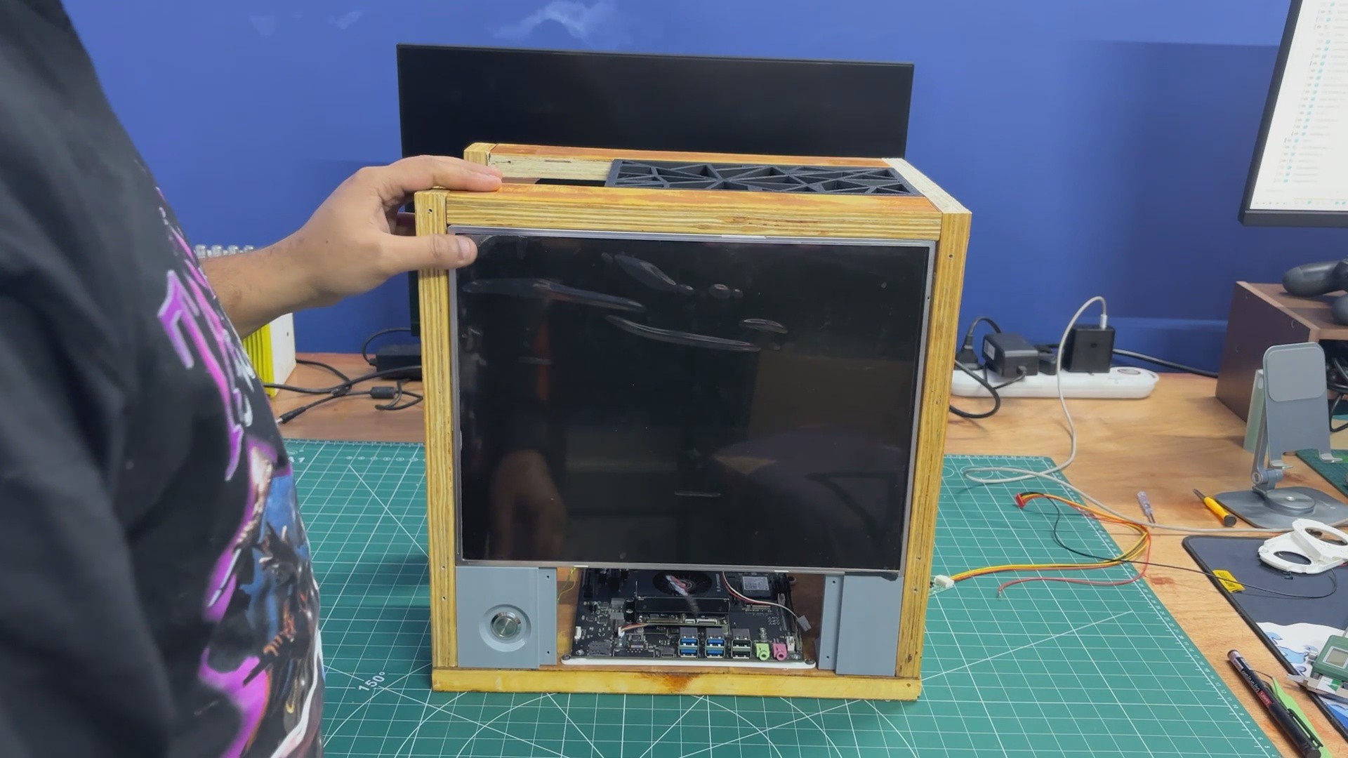
RESULT
Here’s the final result of this simple yet time-intensive build: Parallel PC—Wood Edition. It’s a balanced blend of wood and 3D-printed components, brought together to create a custom all-in-one PC that features not one, but two different computing platforms. One system is an ARM-based SBC, while the other is an x86 machine powered by a mobile processor.
Having two computers in a single enclosure allows us to switch between platforms depending on the task. We can work on Raspberry Pi–based projects and embedded development, then seamlessly switch over to x86 for workloads that require it. In our case, the LattePanda MU runs Bazzite, giving us access to Steam and enabling proper PC gaming—all within the same machine.
 Arnov Sharma


Discussions
Become a Hackaday.io Member
Create an account to leave a comment. Already have an account? Log In.