 Stanislav Britanishskii
Here is the latest version I have
DIY 3D-printed manipulator from off-the-shelf parts and random steppers, ESP32-based control with a simple API over USB, Bluetooth and WiFi.
Already have an account? Log in.
To make the experience fit your profile, pick a username and tell us what interests you.
Here is the latest version I have
Since the last couple of logs quite a lot changed on the “brains” side of RoboArm, so here’s a quick recap up to today (27.01.2026).
A bit over two weeks ago I printed and assembled a much more solid base for the arm. I definitely overused plastic, but at least now it doesn’t feel like it will fold in half when the shoulder moves. Around the same time I set up a PyBullet simulation of the arm, so I could test motion control without abusing the real servos on every experiment. Not all joints behaved exactly as expected in simulation at first, but it was good enough to start playing with kinematics.
About a week ago I implemented the first operational inverse kinematics controller. The control flow looks like this:
a small web server runs on my laptop
my phone connects to a page with a couple of joysticks
the laptop sends joystick data via UDP to the ESP32 on the arm
the joysticks control the desired position of the gripper in space, and the IK tries to move the arm there
In simulation this worked more or less fine. There were some constant offsets, but the motion itself looked sane. On the real arm, though, it was a different story:
when I moved the gripper further away from the base, it would drop down
when I brought it closer, it would go way too high
At first that looked like a classic “servos are weak / gravity wins” situation, but the behavior was wrong even without heavy load, so something else was off.
Today I finally found one major culprit: the bottom joint servo actually has 270° of travel, and I was treating it as a “normal” 180° servo in my angle mapping. That meant the controller and the hardware completely disagreed on what any given angle meant, which showed up as those weird position offsets when moving the hand forwards/backwards.
After fixing the mapping for that servo, the situation improved a lot. The big crazy offset when reaching forward is gone, and the arm now follows the commanded positions in a way that at least looks physically reasonable. It’s still not perfect – there is some distance between desired coordinates and where the gripper actually ends up – but now it’s in a range where tuning, better offsets and maybe some calibration should be enough.
I also changed the elbow joint limits so it can bend up to about 135° in one direction and only 45° in the other. This technically reduces the total reachable volume, but it makes the useful working area on one side of the arm much bigger, which fits the setups I have in mind for real tasks later.
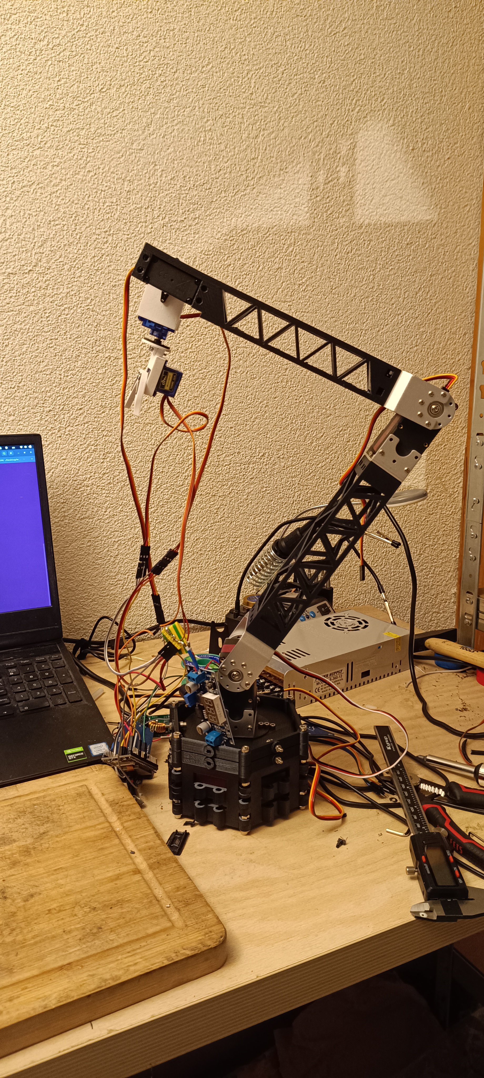
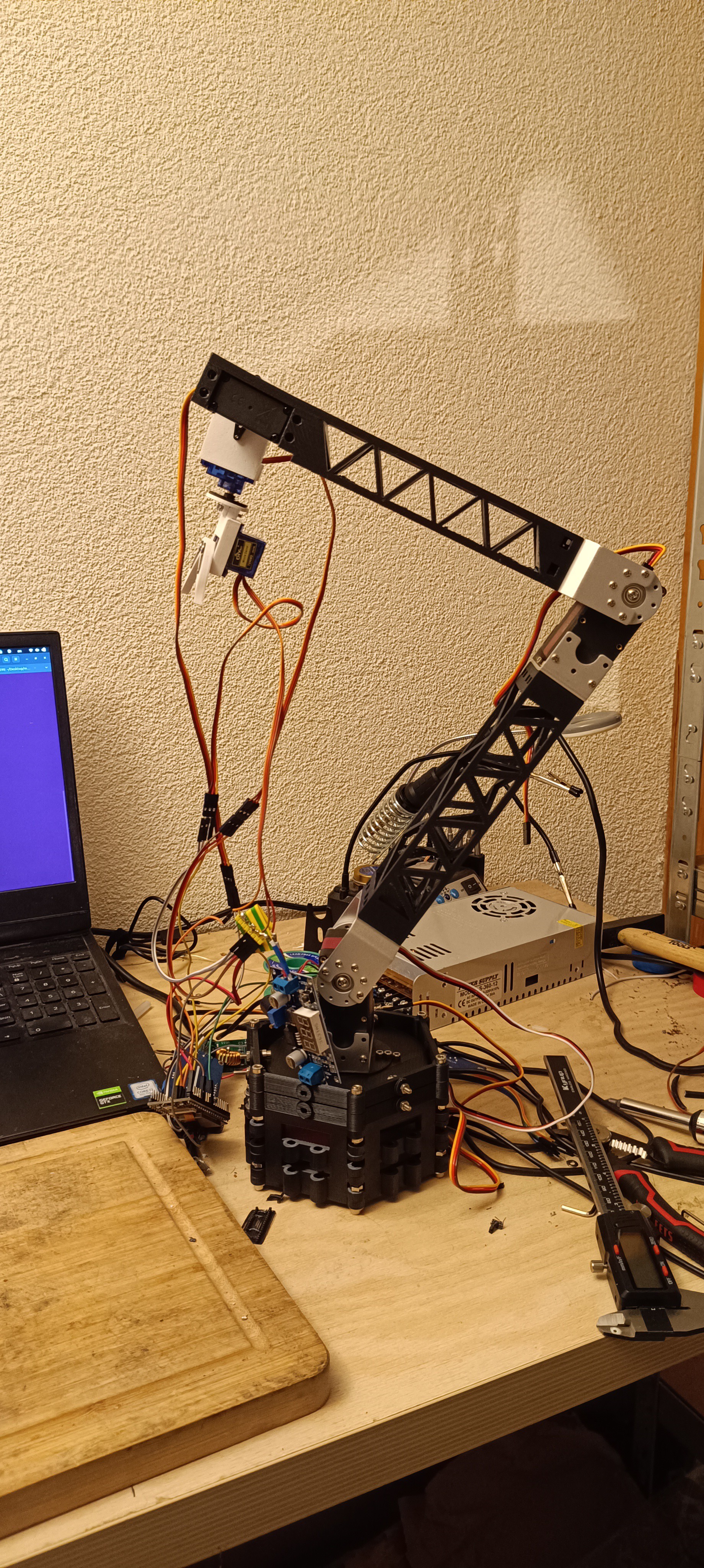
The video below shows the current state as of today: RoboArm moving under IK control, driven from the joystick interface, with the base angle finally behaving as expected instead of fighting the math.
Since the last log quite a lot happened: I burned a power supply, ordered more parts, and mostly finished the arm mechanics.
For the upper and lower arm segments I borrowed the look from crane booms. The lattice structure with triangular cutouts turned out to be surprisingly light and stiff, and was very easy to model in FreeCAD – just a few sketches and patterned triangles. The photo shows the first full “skeleton” of the arm assembled and moving.
Cabling is still a disaster. I’m still using random jumper wires and too many soldered joints, which leads to frequent short circuits. That’s how I killed the previous power supply. The new one seems to survive better (probably has slightly less terrible protection), but these cheap units have plenty of Amazon reviews with pictures of actual flames, so I don’t fully trust it. I’ve ordered proper cables and connectors; they should arrive at the end of this week or the beginning of next.
For the rotating base I decided to use a 60 kg servo, same model as in the elbow. It’s weaker than the 150 kg servo in the shoulder, but it’s also much cheaper. To reduce the load on the base servo I designed a circular platform the arm mounts to, and that ring is held between bearings attached to the base body. The servo just has to drive rotation; the bearings carry most of the weight. It’s working, but the whole base is still too unstable, so next step is a bottom part that clamps to the table with some printable clamp design I’ll probably steal from the internet.
Overall, the results so far are better than I expected. I was mentally prepared for a lot more setbacks at this stage. There is still a long way to go, but seeing the full-length arm move on the bench is very motivating.
Day before yesterday I made the first version of the gripper. As of now I’m not very happy with it. It runs with gears at a 2:1 ratio to the servo, the fingers are straight and they don’t even align that well. It works, but it doesn’t look reliable or precise enough for what I want.
Because of that I’m planning to remake the gripper completely. The current idea is to have two servos, each directly driving one finger instead of going through a shared gear train. Hopefully this will give me better control, less backlash and easier tuning.
Today I got to the first version of the wrist. In its current form it can:
grasp with the fingers
rotate them
tilt them
I’ve just started printing a lower arm piece – not the full length, but enough for initial testing with the wrist and gripper attached. I’ll print a second part later for more stability once I know the geometry actually works.
On the wiring side I realized I need better cables and proper connectors. Soldering everything directly is a terrible idea for repairability, development or any kind of iteration. I ordered a bunch of connectors and cables (AliExpress turned out to be a lot cheaper than Amazon for small parts), they should arrive in about a week.
So far the mechanical results look promising, but there is still a long way to go even just for the hardware. And the software side is going to be the real headache: coordinating joints, building a usable API on the ESP32 and maybe integrating some basic vision later.
Today the project finally moved from “thinking about motors” to an actual moving piece of hardware.
The current idea is to keep the ESP32 as a fairly dumb low-level controller: it uses its built-in PWM channels to drive the servos and just forwards commands from a “real” controller (laptop, Pi, etc.) over serial or UDP. The ESP doesn’t do any serious planning, it’s just a gateway between higher-level logic and the servos.
So far I’ve implemented:
Serial listener for direct wired control
UDP listener for control over WiFi
Both forwarding commands to two test servos, just to prove the concept
For early experiments I’m using my old 9 g servos from the first versions of RoboDog. They’re weak and noisy, but perfect for burning time instead of expensive hardware.
At some point I stumbled upon a YouTube video of a guy using strings to drive joints and keep the heavy motors at the base. That idea is now on the list: if I can keep all the servos at the bottom and only run linkages/cables up the arm, I can reduce weight and stress on the joints a lot.
-----------------------------------------------------------------
Since I still don’t have the “final” motors and mechanics sorted out, I decided to build a small, dirty prototype arm just to test the control pipeline end-to-end.
Reused some 3D parts from RoboDog
Found a gripper model online
Designed a couple of simple connectors
Threw everything together using a breadboard instead of proper soldering
And, in very barbaric fashion, held some parts together with tape
Powered it from the same terrifying 5 V / 30 A metal power supply I used earlier for other tests. The ESP32 is running over WiFi with UDP commands and hasn’t given me any trouble so far.
Surprisingly, in about 4–5 hours from scratch I ended up with a fully assembled small arm that can actually move things around (manually controlled for now). For a one-day hack using leftover parts and tape, I’m pretty happy with the result.
Video: prototype arm moving a small object –
This prototype won’t be the final arm, but it already proves that:
ESP32 + WiFi/UDP control works fine
The basic command pipeline is sane
Even with 9 g servos and tape, the idea isn’t completely stupid
Next steps: clean up the control protocol a bit, think about the real mechanical design, and wait for the “serious” servos to arrive.
For the very first step of this project I didn’t actually touch any hardware. Instead, I wrote a tiny shell script to auto-create log files so I don’t have to do it manually every time. Classic: automating the logging system before doing any real tests.
For the initial tests I planned to use some cheap stepper motors I bought on Amazon a while ago – the usual 5-wire steppers with ULN2003 driver boards sold by Elegoo. I have almost no real experience with steppers, so I thought it would be a good chance to learn something.
Very quickly it turned out they are not a great fit for what I want. They only give me open-loop step control, no actual feedback, no current control, nothing “smart” I could use to estimate torque or position under load. Looking back, I’m not even sure why I bought them in the first place – I treated them like some kind of magic solution without reading enough about what I’d actually need for a manipulator.
So I ended up with three main paths:
The easy way: use hobby servos similar to the ones from RoboDog, maybe slightly more powerful. The downside is the same as with the dog: no real internal state feedback, just the angle I asked for and hope it’s close to reality.
DC motors + external sensing: use DC motors with external current control and either rotary potentiometers or absolute encoders for joint feedback. Potentiometers are a lot cheaper, but this adds more electronics and mechanical complexity.
Cheat mode: use Dynamixel-style smart servos. They give me everything I want (position, speed, current, bus control), but at a price that explodes very quickly, and there is potential extra pain in integrating them properly.
After a long back-and-forth with ChatGPT and some thinking, I decided to go with “normal” servos, but not the 1 euro kind. I ordered a batch of much more serious servos, around 60 euro per piece, and I’ll probably need one more later. That hurts the “low budget” idea a bit, but it should give me more reliable joints and simpler electronics than a full DC + encoder stack.
While I’m waiting for the good servos to arrive, I’ll start working on the software side and test the basic control logic using my old cheap 9 g servos left over from early RoboDog versions. They are not strong enough for the final arm, but they are good enough to prototype the API and basic joint control without burning expensive hardware on day one.