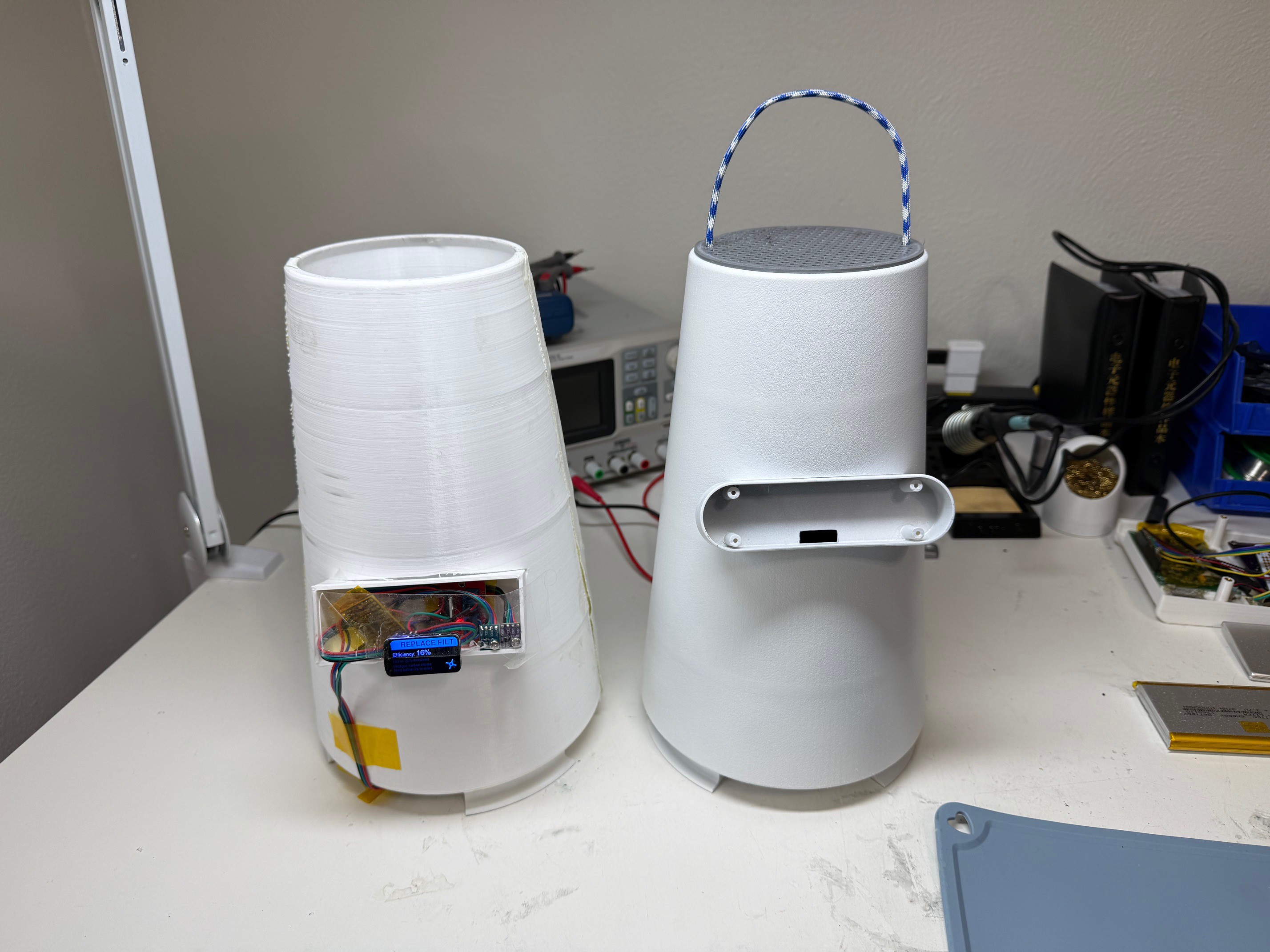
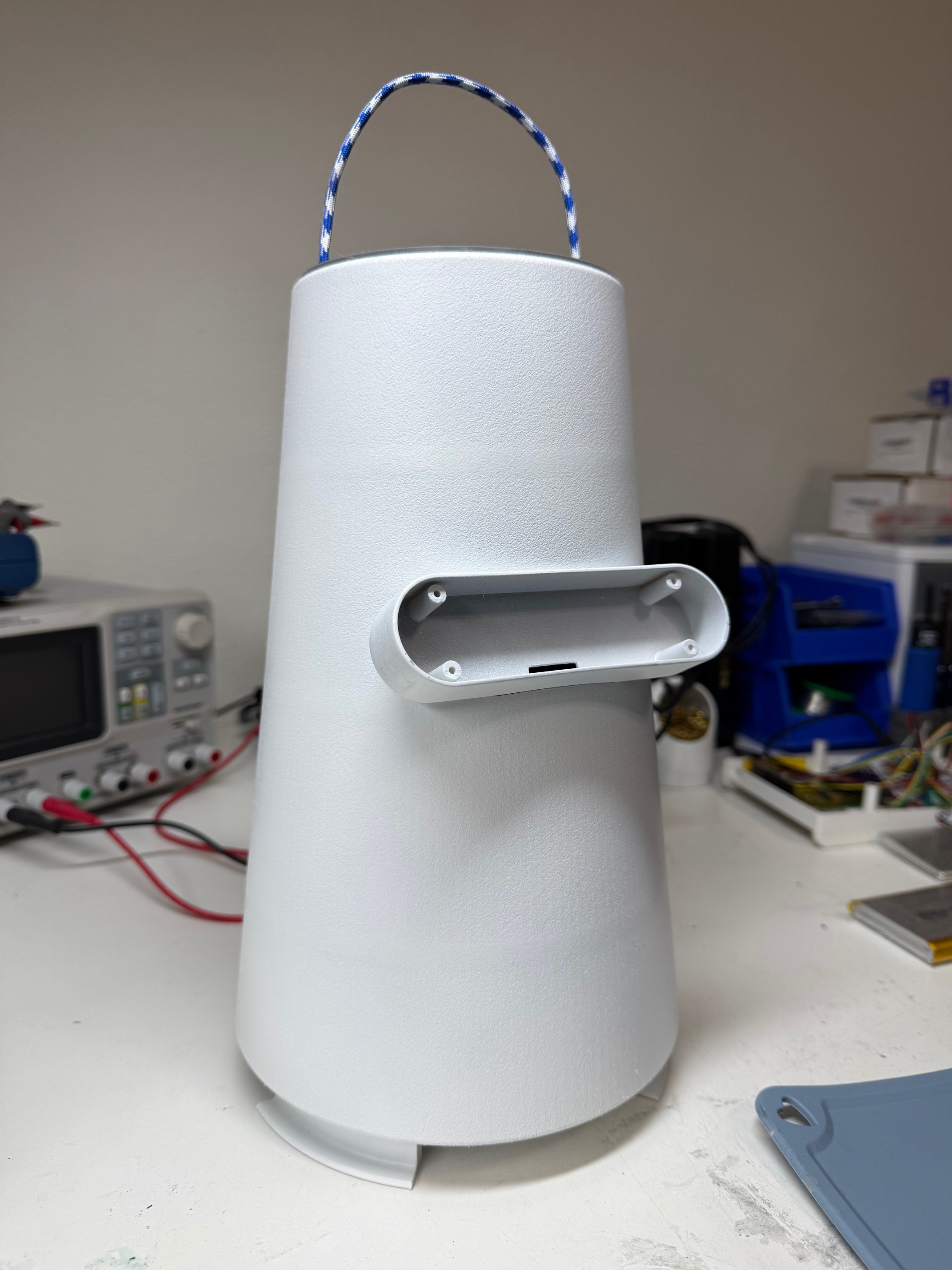
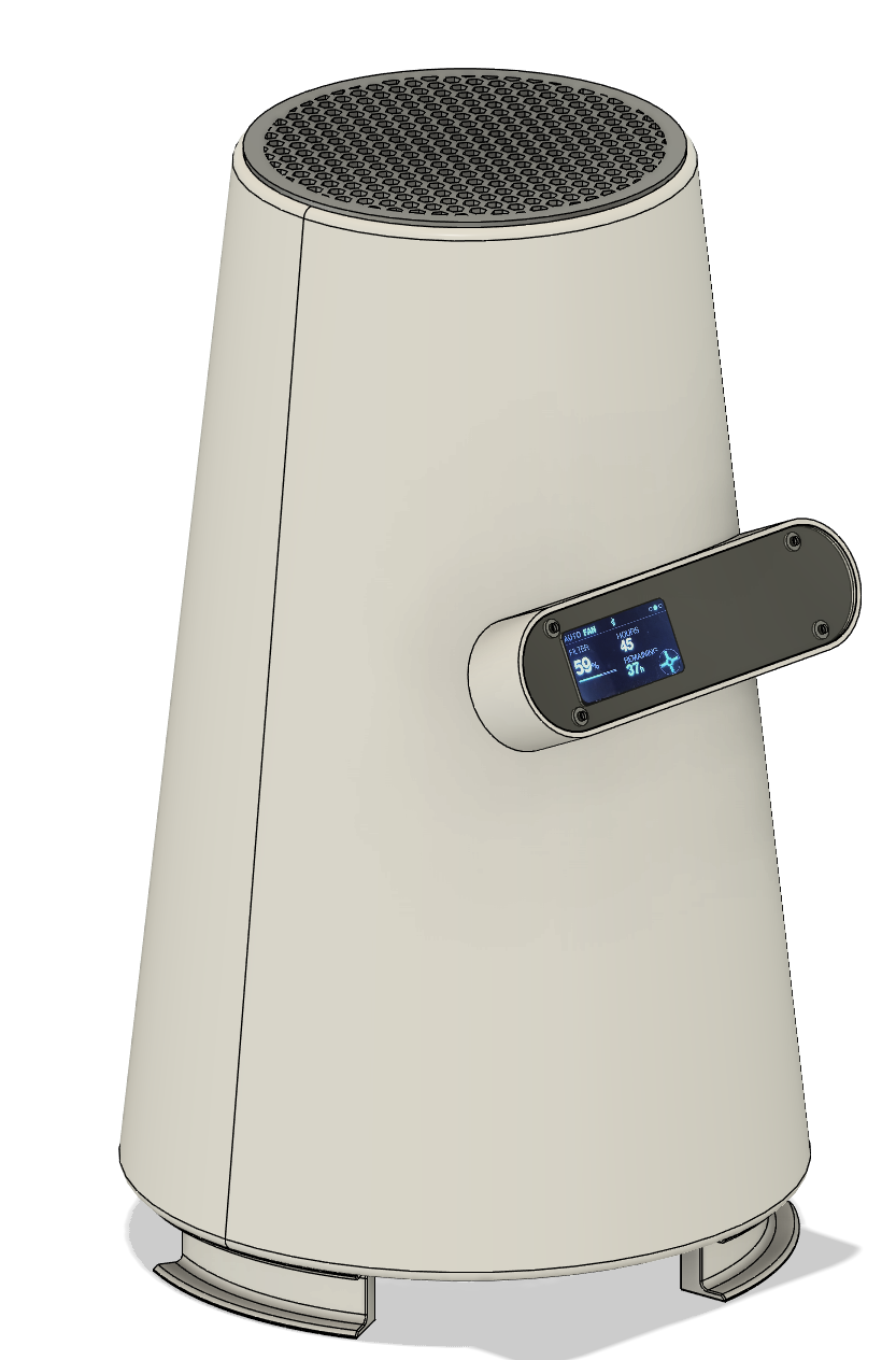
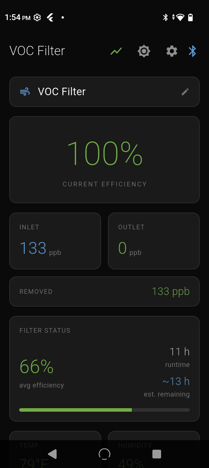
Most carbon filters just run until you remember to change them. This one actually knows when it's dying. Dual SGP30 sensors measure VOC before and after the filter, while the firmware learns your lab's baseline, detects stuck sensors, and calculates true efficiency based on what's actually removable - not naive inlet/outlet ratios. Tracks filter degradation over time and predicts hours remaining. ESP32-C6 runs the show with a 320x172 display, BLE connectivity for a Flutter app, and automatic fan control that only runs when needed. Built for resin 3D printing but works anywhere you need to know your air is actually getting cleaned.
Was not supper happy with the original square electronics bay, it was good for prototyping, but I need it to be more product looking.
I loaded up Fusion and worked out this version. The PCB will be colored black and be visible under a 1mm plexiglass cover. I have a schematic/PCB design going and when that is done I will send off for samples. The PCB will have all sensors and the JST connectors on it except for the outlet VOC sensor. The new electronics bay is a much more pleasing shape and is smaller since I plan on going with a custom PCB. The bay is also higher on the unit and will help the inlet VOC sensor on the board be closer wit the inlet air.
Also got around to making the fast swap filter that will be used for it. It is quite large and features a honeycomb prefilter/inlet and 1.5-2 cups loose activated carbon and then spiral of carbon mat, all wrapped in black paper.
Before building a real app, I validated everything with nRF Connect first. Scan, connect, discover services, send commands, verify response. This caught firmware bugs before I ever touched Flutter - saved hours of debugging the wrong layer.
Once the device protocol was solid, I moved to Flutter. The BLE part was actually easy. The fight was Android itself: permission handling across OS versions, background scan behavior, and write/notification timing quirks. Classic mobile pain.
My approach: get scan + connect + one confirmed write working reliably before building anything else. Once that foundation was solid, the rest was normal app development - state management, UI, logging, graphs.
This was also my first Flutter app. Figured I'd learn on something real instead of another tutorial project.
What the app does:
Connect & manage multiple filters (up to 6 units) — quick select, reconnect, and keep each one's identity straight
Live dashboard control — fan PWM / auto mode, basic settings, and "is it actually running right now" status
Real-time sensor streaming — inlet/outlet VOC, temp/humidity, with smooth updates
Built-in graphing / trending — time-series plots for sensor data and filter performance so you can see what's happening, not guess
Tap-to-inspect graph data — click a point to pull exact values + timestamp (nice for debugging and "what happened here?" moments)
Export / share logs — CSV output for deeper analysis, backups, or sending to someone without screenshots
Nothing fancy, but it works because I didn't skip the nRF validation step.
Three-module setup... clean, simple, and it does what it needs to do:
1) Main Firmware (the “keep the thing alive” brain)
This handles the display, BLE stack, fan control, button input, and sensor polling.
The UI cycles through four pages: main readings, filter status, environment, and a scrolling diagnostics page where I can literally watch what the adaptive system is thinking in real time.
2) Adaptive Sensor Module (the “learning” part)
This is where the system gets smarter instead of just spitting out raw numbers.
Signal filtering smooths the sensor noise (because VOC sensors are drama queens).
Calibration learns the relationship between inlet/outlet sensors (because they never match perfectly).
Environmental compensation corrects for temperature/humidity changing the readings over time.
Baseline tracking watches the “floor” shift and flags when a sensor starts acting suspicious.
3) Event & Filter Module (the “what does this mean?” part)
This tracks what’s happening in the real world and turns it into useful outputs:
Detects events like active printing vs idle
Calculates true filter efficiency (not the naive inlet/outlet ratio)
Tracks filter health over time
Learns usage patterns and predicts remaining life
Gotchas & Lessons Learned (aka: why the first version lied to me)
Efficiency math is way harder than it looks.
My first pass was the obvious approach: inlet vs outlet. Super clean. Totally wrong.
Because if your room baseline is already garbage (or already clean), the raw ratio is misleading. Once I accounted for baseline air quality and what’s realistically removable, the numbers started matching real filter performance.
Sensors drift. Hard.
VOC sensors don’t “measure truth.” They measure vibes.
They can get stuck reporting the wrong value for hours like they’re gaslighting you. So I added drift detection + compensation logic instead of trusting raw readings.
Calibration isn’t optional.
Two “identical” sensors won’t read the same in identical air. Ever.
So the system has to learn the offset between the pair, or you’re just building a fancy random number generator.
Persistence matters.
All learned parameters save to non-volatile memory so it doesn’t forget everything after a power cut.
But you can’t write constantly or you’ll wear out flash/EEPROM… and you can’t write too rarely or you lose learning when power drops at the worst time. So yeah, balancing save frequency was a whole thing.